EXFO FVA-60B User manual

-~
ARTISAN
®
~I
TECHNOLOGY
GROUP
Your definitive source
for
quality
pre-owned
equipment.
Artisan Technology
Group
Full-service,
independent
repair
center
with
experienced
engineers
and
technicians
on staff.
We
buy
your
excess,
underutilized,
and
idle
equipment
along
with
credit
for
buybacks
and
trade-ins
.
Custom
engineering
so
your
equipment
works
exactly as
you
specify.
•
Critical
and
expedited
services
•
Leasing
/
Rentals/
Demos
• In
stock/
Ready-to-ship
•
!TAR-certified
secure
asset
solutions
Expert
team
ITrust
guarantee
I
100%
satisfaction
All
tr
ademarks,
br
a
nd
names, a
nd
br
a
nd
s a
pp
earing here
in
are
th
e property of
th
e
ir
r
es
pecti
ve
ow
ner
s.
Find the Exfo FVA-60B at our website: Click HERE
User Guide
P/N: 1011968
April 2002
If the equipment described herein
bears the symbol, the said
equipment complies with the
applicable European Union
Directive and Standards mentioned
in the Declaration of Conformity.
Variable Optical
Attenuator
FVA-60B
User Guide
P/N: 1011968
April 2002
If the equipment described herein
bears the symbol, the said
equipment complies with the
applicable European Union
Directive and Standards mentioned
in the Declaration of Conformity.
Variable Optical
Attenuator
FVA-60B
User Guide
P/N: 1011968
April 2002
If the equipment described herein
bears the symbol, the said
equipment complies with the
applicable European Union
Directive and Standards mentioned
in the Declaration of Conformity.
Variable Optical
Attenuator
FVA-60B
Artisan Technology Group - Quality Instrumentation ... Guaranteed | (888) 88-SOURCE | www.artisantg.com

All rights reserved. No part of this publication may be reproduced, stored in a
retrieval system, or transmitted in any form, be it electronically, mechanically, or by
any other means such as photocopying, recording, or otherwise, without the prior
written permission of EXFO Electro-Optical Engineering Inc. (EXFO).
Information provided by EXFO is believed to be accurate and reliable. However, no
responsibility is assumed by EXFO for its use nor for any infringements of patents or
other rights of third parties that may result from its use. No license is granted by
implication or otherwise under any patent rights of EXFO.
EXFO’s Commerce And Government Entities (CAGE) code under the North Atlantic
Treaty Organization (NATO) is 0L8C3.
The information contained in this publication is subject to change without notice.
© 2002 EXFO Electro-Optical Engineering Inc.
Words that EXFO considers trademarks have been identified as such. However,
neither the presence nor absence of such identification affects the legal status of
any trademark.
Units of measurement in this document conform to SI standards and practices.
Artisan Technology Group - Quality Instrumentation ... Guaranteed | (888) 88-SOURCE | www.artisantg.com

FVA-60B iii
Contents
Certification Information .................................................................................. v
1 Introducing the FVA-60B Variable Optical Attenuator ............ 1
Display Description ........................................................................................... 1
Keypad Description ........................................................................................... 1
Secondary Keypad Functions ............................................................................ 2
Connector Panel Description ............................................................................. 2
2 Safety Information ................................................................... 3
Safety Conventions ........................................................................................... 3
Laser Safety Information ................................................................................... 3
3 Operating the FVA-60B Variable Optical Attenuator ............... 5
Calibrating the Unit .......................................................................................... 5
Using the Absolute Mode ................................................................................. 5
Using the Relative Mode ................................................................................... 6
Using the X + B Mode ...................................................................................... 6
Programming Wavelengths .............................................................................. 7
Setting Attenuation Step Sizes ......................................................................... 7
Programming the Unit ...................................................................................... 8
Initiating the Program Execution ...................................................................... 9
4 Using the RS-232 Interface and Software .............................. 11
Installing the Software .................................................................................... 11
Connecting the RS-232 Interface Cable .......................................................... 12
Starting the Interface Application ................................................................... 12
Using the Interface Application ...................................................................... 12
Understanding the General Operation Menu .................................................. 12
Understanding the Program Menu ................................................................. 13
Viewing Source Files ....................................................................................... 13
Using Interface Commands ............................................................................. 14
5 Maintenance ............................................................................ 15
Cleaning the Front Panel ................................................................................. 15
Cleaning Fixed Connectors .............................................................................. 16
Cleaning Connectors Equipped with EUI/EUA Adapters .................................. 18
Cleaning Detector Ports .................................................................................. 21
Recharging the Battery Pack ........................................................................... 22
Replacing the 9 V Alkaline Battery .................................................................. 22
Recalibrating the Unit ..................................................................................... 22
6 Troubleshooting ...................................................................... 23
Solutions to Common Problems ..................................................................... 23
Finding Information on the EXFO Web Site .................................................... 23
Contacting the Technical Support Group ........................................................ 24
Transportation ................................................................................................ 24
Artisan Technology Group - Quality Instrumentation ... Guaranteed | (888) 88-SOURCE | www.artisantg.com

Contents iv
7 Warranty .................................................................................. 25
General Information ....................................................................................... 25
Liability ........................................................................................................... 25
Exclusions ....................................................................................................... 26
Certification .................................................................................................... 26
Service and Repairs ......................................................................................... 26
EXFO Service Centers Worldwide .................................................................... 27
A Technical Specifications .......................................................... 29
Artisan Technology Group - Quality Instrumentation ... Guaranteed | (888) 88-SOURCE | www.artisantg.com

FVA-60B v
Certification Information
F.C.C. Information
Electronic test equipment is exempt from Part 15 compliance (FCC) in the United
States, but EXFO makes reasonable efforts to ensure this compliance.
Information
Electronic test equipment is subject to the EMC Directive in the European Union.
The EN61326 standard prescribes both emission and immunity requirements for
laboratory, measurement, and control equipment. This unit has been tested and
found to comply with the limits for a Class A digital device. Please refer to the
Declaration of Conformity.
Independent Laboratory Testing
This unit has undergone extensive testing according to the European Union
Directive and Standards. All pre-qualification tests were performed internally, at
EXFO, while all final tests were performed externally, at an independent, accredited
laboratory. This guarantees the unerring objectivity and authoritative compliance of
all test results.
Artisan Technology Group - Quality Instrumentation ... Guaranteed | (888) 88-SOURCE | www.artisantg.com

Certification Information vi
Electro-Optical Engineering
Application of Council Directive(s): 73/23/EEC - The Low Voltage Directive
89/336/EEC - The EMC Directive
Manufacturer’s Name: EXFO ELECTRO-OPTICAL ENG.
Manufacturer’s Address: 465 Godin Avenue
Vanier, Quebec
Canada G1M 3G7
(418) 683-0211
Equipment Type/Environment: Industrial Scientific Equipment
Trade Name/Model No.: FVA-60B, Variable Optical Attenuator
Year of Conformity Assessment: 1997
Standard(s) to which Conformity is Declared:
EN 61010-1:1990 Safety Requirements for Electrical Equipment for Measurement, Control, and
Laboratory Use, Part 1: General Requirements
EN 55011:1993 Limits and methods of measurement of radio disturbance characteristics of
industrial, scientific, and medical equipment
EN 50082-2:1995 Electromagnetic Compatibility Generic immunity standard - Part 2: Industrial Environment
I, the undersigned, hereby declare that the equipment specified above conforms to the above Directive and Standards.
Manufacturer
Signature:
Full Name: Stephen Bull, E. Eng
Position: Vice-President Research and
Development
Address: 465 Godin Avenue Vanier, Quebec,
Canada
Date: avril 4, 2002
DECLARATION OF CONFORMITY
Artisan Technology Group - Quality Instrumentation ... Guaranteed | (888) 88-SOURCE | www.artisantg.com
FVA-60B 1
1 Introducing the FVA-60B
Variable Optical
Attenuator
The FVA-60B is a variable optical attenuator used for bit error rate and system
testing, optical margin analysis, calibration verification and component testing. It
can be configured for singlemode or multimode fibers; calibrated wavelengths are
either 1310/1550 nm or 850/1300 nm respectively.
The FVA-60B is powered by the built-in rechargeable Ni-MH battery pack, the 9 V
alkaline battery, or the AC adapter/charger.
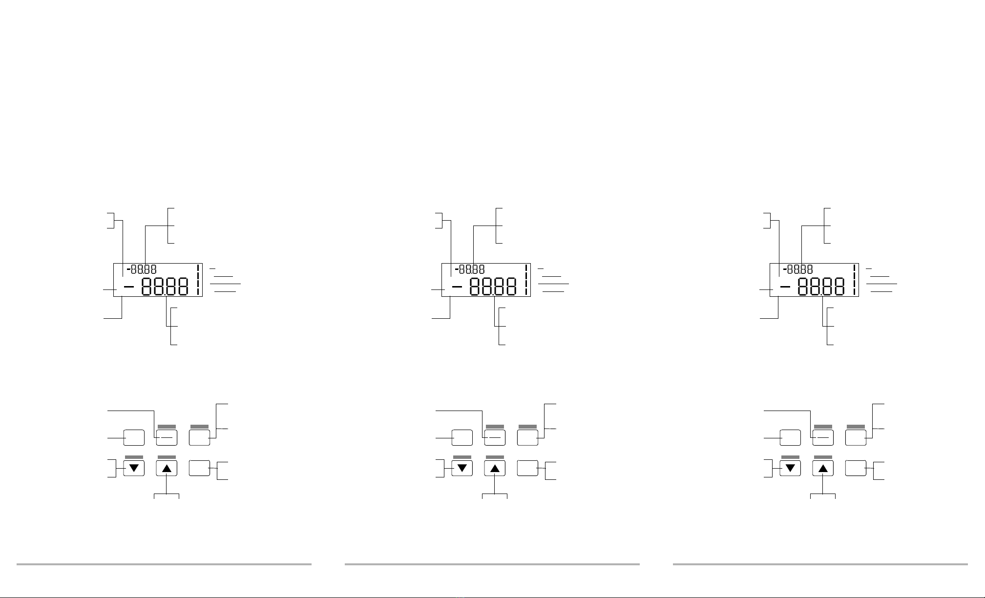
Display Description
Keypad Description
dB
nm
Ni-MH
AC
9V
working
LO BAT
SHIFT
CHARGE
dB
Lights up if low
Ni-MH battery pack
Operating wavelength
(nm) in Absolute mode
Total attenuation (dB) in
relative or X + B mode
Step number and time interval during
program setup and execution
Secondary function
(shift + key)
activated
Ni-MH battery pack
being recharged
Various information during
program and step size setup
9 V battery operation
Calibration in progress
Ni-MH battery operation
AC charger/adapter operation
Total attenuation (dB) in
Absolute mode
Relative attenuation (dB) in
relative or X + B mode
Flashes if low Ni-MH and
9 V batteries
on / off program
shift/exit
atten.
rel.
Decreases user-defined
parameters during
program setup
Increases attenuation
(hold for rapid scanning)
Increases user-defined parameters
during program setup
Accesses secondary
keypad functions
Exits program
execution or setup
Executes program and
activates program setup
Toggles between
user-defined
parameters
Toggles between absolute
and Relative modes
Decreases attenuation
(hold for rapid
scanning)
Powers unit on or off
FVA-60B 1
1 Introducing the FVA-60B
Variable Optical
Attenuator
The FVA-60B is a variable optical attenuator used for bit error rate and system
testing, optical margin analysis, calibration verification and component testing. It
can be configured for singlemode or multimode fibers; calibrated wavelengths are
either 1310/1550 nm or 850/1300 nm respectively.
The FVA-60B is powered by the built-in rechargeable Ni-MH battery pack, the 9 V
alkaline battery, or the AC adapter/charger.
Display Description
Keypad Description
dB
nm
Ni-MH
AC
9V
working
LO BAT
SHIFT
CHARGE
dB
Lights up if low
Ni-MH battery pack
Operating wavelength
(nm) in Absolute mode
Total attenuation (dB) in
relative or X + B mode
Step number and time interval during
program setup and execution
Secondary function
(shift + key)
activated
Ni-MH battery pack
being recharged
Various information during
program and step size setup
9 V battery operation
Calibration in progress
Ni-MH battery operation
AC charger/adapter operation
Total attenuation (dB) in
Absolute mode
Relative attenuation (dB) in
relative or X + B mode
Flashes if low Ni-MH and
9 V batteries
on / off program
shift/exit
atten.
rel.
Decreases user-defined
parameters during
program setup
Increases attenuation
(hold for rapid scanning)
Increases user-defined parameters
during program setup
Accesses secondary
keypad functions
Exits program
execution or setup
Executes program and
activates program setup
Toggles between
user-defined
parameters
Toggles between absolute
and Relative modes
Decreases attenuation
(hold for rapid
scanning)
Powers unit on or off
Artisan Technology Group - Quality Instrumentation ... Guaranteed | (888) 88-SOURCE | www.artisantg.com
Introducing the FVA-60B Variable Optical Attenuator 2
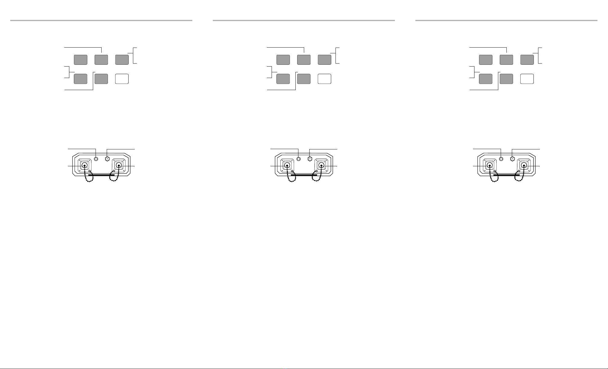
Secondary Keypad Functions
Note: To access a secondary function, press shift, then the corresponding key.
Connector Panel Description
X + B
shift
STEP SIZE
CALIBRATE
λ
SELECT
Activates X + B mode
Toggles between
programmed wavelengths
Activates Wavelength
Programming mode
Re-positions internal
optics to minimum
attenuation
Activates step size setup
and toggles between
available step sizes
Activates variable
step size setup
FVA-60B
RS-232 12 VDC
INPUT OUTPUT
Input optical
port
Supplies DC power to
unit and recharges
built-in Ni-MH battery
pack
Connects unit to PC for
remote control via RS-232
interface cable
Output optical port
Introducing the FVA-60B Variable Optical Attenuator 2
Secondary Keypad Functions
Note: To access a secondary function, press shift, then the corresponding key.
Connector Panel Description
X + B
shift
STEP SIZE
CALIBRATE
λ
SELECT
Activates X + B mode
Toggles between
programmed wavelengths
Activates Wavelength
Programming mode
Re-positions internal
optics to minimum
attenuation
Activates step size setup
and toggles between
available step sizes
Activates variable
step size setup
FVA-60B
RS-232 12 VDC
INPUT OUTPUT
Input optical
port
Supplies DC power to
unit and recharges
built-in Ni-MH battery
pack
Connects unit to PC for
remote control via RS-232
interface cable
Output optical port
Artisan Technology Group - Quality Instrumentation ... Guaranteed | (888) 88-SOURCE | www.artisantg.com

FVA-60B 3
2 Safety Information
Safety Conventions
You should understand the following conventions before using the product
described in this manual:
WARNING
Refers to a potential personal hazard. It requires a
procedure which, if not correctly followed, may result
in bodily harm or injury. Do not proceed unless you
understand and meet the required conditions.
CAUTION
Refers to a potential product hazard. It requires a
procedure which, if not correctly followed, may result
in component damage. Do not proceed unless you
understand and meet the required conditions.
IMPORTANT
Refers to any information regarding the operation of the
product which you should not overlook.
Laser Safety Information
WARNING
Do not install or terminate fibers while a laser source is active.
Never look directly into a live fiber and ensure that your eyes
are protected at all times.
WARNING
Use of controls, adjustments and procedures for operation and
maintenance other than those specified herein may result in
hazardous radiation exposure.
WARNING
Use of optical instruments with this product will increase eye
hazard.
Artisan Technology Group - Quality Instrumentation ... Guaranteed | (888) 88-SOURCE | www.artisantg.com

Artisan Technology Group - Quality Instrumentation ... Guaranteed | (888) 88-SOURCE | www.artisantg.com
FVA-60B 5
3 Operating the FVA-60B
Variable Optical
Attenuator
Calibrating the Unit
For optimum performance, the unit should be calibrated before each test session.
To calibrate the unit:
1. Power on the unit.
2. Press shift/exit, then CALIBRATE. The internal motor runs for a few seconds
(adjusting attenuation to minimum) and the working marker is displayed.
To check the minimum insertion loss for a particular wavelength, select the
wavelength and perform a calibration. The value displayed after calibration is the
minimum insertion loss at the selected wavelength.
Note: Performing a calibration sets the FVA-60B to Absolute mode.
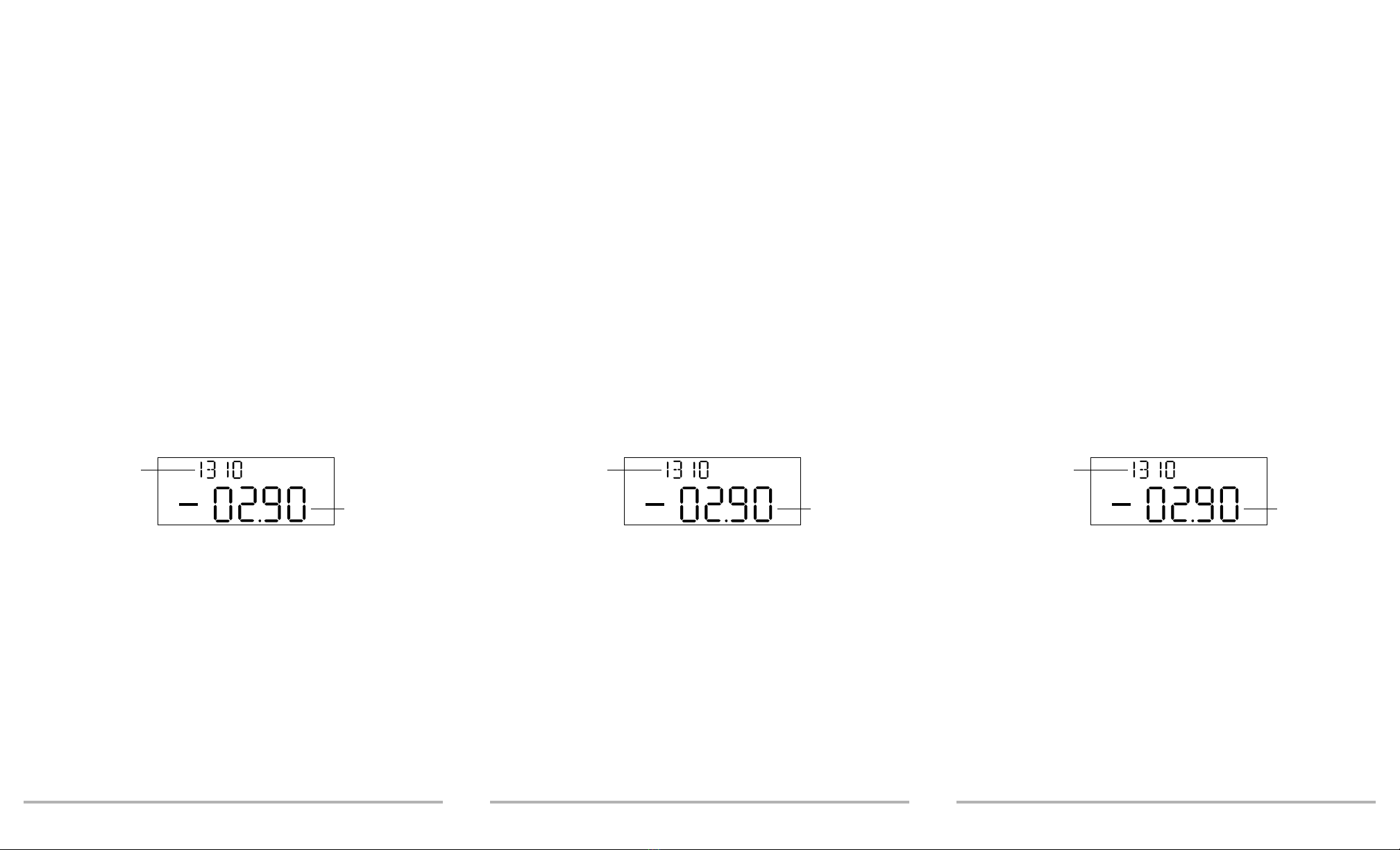
Using the Absolute Mode
The Absolute mode displays the current wavelength and attenuation settings. It is
selected by default when powering on the FVA-60B. If the unit was scanning (setting
a new attenuation value) when it was powered off, the scan will be completed at
power-up.
Note: The attenuation value is the actual insertion loss between the input and
output ports including connectors.
dB
nm
Wavelength
Attenuation
FVA-60B 5
3 Operating the FVA-60B
Variable Optical
Attenuator
Calibrating the Unit
For optimum performance, the unit should be calibrated before each test session.
To calibrate the unit:
1. Power on the unit.
2. Press shift/exit, then CALIBRATE. The internal motor runs for a few seconds
(adjusting attenuation to minimum) and the working marker is displayed.
To check the minimum insertion loss for a particular wavelength, select the
wavelength and perform a calibration. The value displayed after calibration is the
minimum insertion loss at the selected wavelength.
Note: Performing a calibration sets the FVA-60B to Absolute mode.
Using the Absolute Mode
The Absolute mode displays the current wavelength and attenuation settings. It is
selected by default when powering on the FVA-60B. If the unit was scanning (setting
a new attenuation value) when it was powered off, the scan will be completed at
power-up.
Note: The attenuation value is the actual insertion loss between the input and
output ports including connectors.
dB
nm
Wavelength
Attenuation
Artisan Technology Group - Quality Instrumentation ... Guaranteed | (888) 88-SOURCE | www.artisantg.com

Operating the FVA-60B Variable Optical Attenuator 6
Using the Relative Mode
The Relative mode allows the user to establish a 0.00 dB reference attenuation at
any value within the unit’s attenuation range.
To establish a reference:
1. Ensure the unit is in Absolute mode. See Using the Absolute Mode on page 5.
2. Select the appropriate wavelength by pressing shift/exit, then λSELECT. To
program wavelengths, see Programming Wavelengths on page 7.
3. Set the desired attenuation level by using or . For details about
how to set attenuation, see Setting Attenuation Step Sizes on page 7.
4. Press atten./rel. The smaller digits display the total attenuation, while the larger
digits display the attenuation with respect to the selected reference
(i.e., 00.00 dB).
5. If you now change the attenuation, the smaller digits display the total
attenuation introduced by the FVA-60B, while the larger digits display the
relative loss (or gain) with respect to the selected reference.
Using the X + B Mode
The X + B mode displays the sum of X + B values, where X is the actual attenuation
introduced by the unit, and B is some offset value, possibly a power level or a
known system loss. The X + B mode allows the user to display attenuation readings
as any value between −99.95 dB and 99.95 dB.
To use the X + B mode:
1. Ensure the unit is in Absolute mode. See Using the Absolute Mode on page 5.
2. Select the appropriate wavelength by pressing shift/exit, then λSELECT. To
program wavelengths, see Programming Wavelengths on page 7.
3. Set the initial attenuation value X by using or . For details about
how to set attenuation, see Setting Attenuation Step Sizes on page 7.
4. Press shift/exit, then X+B. The larger digits flash and the smaller digits display
the initial attenuation.
5. Set the desired X + B value by using or . The value displayed on
the smaller digits (absolute attenuation) does not change, since setting the
arbitrary X + B value has no influence on the actual attenuation.
6. Press shift/exit when the X + B value is set.
If you now vary the attenuation value X, both the absolute attenuation value and the
X + B value increase or decrease accordingly.
Artisan Technology Group - Quality Instrumentation ... Guaranteed | (888) 88-SOURCE | www.artisantg.com

FVA-60B 7
Programming Wavelengths
The FVA-60B offers calibrated wavelength at ± 30 nm (in 10 nm steps) from the
standard singlemode and multimode wavelengths.
To p r o g r a m w a v e l e n g t hs :
1. Press shift/exit, then λSELECT for three seconds. The currently selected
wavelength flashes.
2. Press or to toggle between available wavelengths.
3. Press program to confirm selection.
4. Repeat step 2 to select a second wavelength and press program to confirm
selection. Upon confirmation of second wavelength, the unit exits the
Wavelength Programming mode.
Note: To see the currently selected wavelength when you are in relative or
X + B mode, switch to the alternate wavelength and back. The new
setting is briefly displayed.
Setting Attenuation Step Sizes
The unit has four attenuation step sizes that permit different scanning speeds and
resolutions:
➤0.05 dB step size and resolution (default when powering on the unit)
➤0.2 dB step size and resolution
➤1 dB step size and resolution
➤User-definable step size with 0.05 dB resolution
Note: Selecting a larger step size allows for faster attenuation scanning.
Standard Step Sizes
To select a standard step size:
1. Press shift/exit, then STEP SIZE.
2. Press STEP SIZE again to toggle between step size options.
3. Press shift/exit to confirm selection.
4. Pressing or changes the attenuation one step.
Note: Selecting one of the three standard step sizes affects the resolution of
the attenuation setting and may cause rounding off of the currently
selected attenuation value.
Artisan Technology Group - Quality Instrumentation ... Guaranteed | (888) 88-SOURCE | www.artisantg.com

Operating the FVA-60B Variable Optical Attenuator 8
User-Definable Step Size
To set the user-definable step size:
1. Press shift/exit, then STEP SIZE for three seconds. The larger digits flash,
indicating the current variable step size setting.
2. Set the desired step size using or . The maximum step size value
is 60.00 dB.
3. Press shift/exit to confirm selection. The variable step size is now programmed
and is the currently selected step size.
Programming the Unit
The unit can be programmed for automatic operation. The program permits up to
60 attenuation steps with a time interval of up to 60 hours (minus one second)
between each step. Attenuation changes between −0.05 dB and −70 dB (minus the
insertion loss) may be introduced. You can define program parameters for each of
the available wavelengths.
To p r o g r a m t h e u n i t :
1. Select the appropriate wavelength by pressing shift/exit, then λSELECT. To
program wavelengths, see Programming Wavelengths on page 7.
2. Press program for three seconds to activate program setup. A flashing value,
between 00 and 59, defines the number of attenuation steps in your program.
Press or to select a number, then press program to confirm the
selection.
3. A flashing value, between 00H and 59H, defines the number of hours in the time
interval. Press or to select a number, then press program to
confirm the selection.
4. A flashing value, between 00: and 59:, defines the number of minutes.
Press or to select a number, then press program to confirm the
selection.
5. A flashing value, between :00 and :59, defines the number of seconds.
Press or to select a number, then press program to confirm
the selection.
6. A flashing value, between −00.00 dB and −70.00 dB, defines the size of each
attenuation step. Press or to select a number in 00.05 dB steps.
The program parameters have now been defined. To cycle through the five
parameters, press program.
7. Press shift/exit to exit the program setup. Your program parameters have
been set.
Note: If you power off the unit before exiting the program definition, all
changes made during the current programming session will be lost.
Artisan Technology Group - Quality Instrumentation ... Guaranteed | (888) 88-SOURCE | www.artisantg.com

FVA-60B 9
Initiating the Program Execution
To initiate the program execution:
1. Set the unit to the appropriate initial attenuation value.
2. Press program. The FVA-60B will start at the initial attenuation value and
automatically increase the attenuation in accordance with program parameters.
Upon completion of the last program step, the unit resets the initial attenuation
value and the program loops.
3. Press shift/exit to end program execution.
Note: If your program attempts to set a value beyond the maximum
attenuation range, the program resets to the first step and loops using
only the steps that fall within the range.
Artisan Technology Group - Quality Instrumentation ... Guaranteed | (888) 88-SOURCE | www.artisantg.com

Artisan Technology Group - Quality Instrumentation ... Guaranteed | (888) 88-SOURCE | www.artisantg.com

FVA-60B 11
4 Using the RS-232
Interface and Software
The RS-232 interface and application software allow remote control of the unit from
a PC. A floppy disk, containing the programming source code (Borland C™), is
delivered as part of the RS-232 kit. Refer to the README.DOC file for up-to-date
information about the FVA-60B application software. To read the file, type
A:README from the DOS command line with the floppy disk inserted in your
floppy drive.
Installing the Software
The following files are included in the root directory of the floppy disk:
Copy the files to your PC’s hard disk.
The LISTINGS directory contains the uncompiled source and header files that were
used to create the interface application.
Note: Make a copy of the RS-232 interface floppy disk and keep the original in
a safe place.
To install the application software on your hard disk, insert the floppy disk into drive
A or B and type the following commands (no spaces) from the DOS command line:
➤C:<enter>
➤CD\<enter>
➤MD FVA60B<enter>
➤CD FVA60B<enter>
➤MD LISTINGS<enter>
➤CD LISTINGS<enter>
➤COPY A:\LISTINGS\*.* C:<enter>
➤CD..<enter>
➤COPY A:\*.* C:<enter>
➤DEMO60B.EXE Remote control program
➤DEMOBW1.BAT Example batch file for non-standard configuration
➤DISPLAY.EXE Program for viewing source code files
➤README.BAT Batch file to read README.DOC
➤README.DOC File containing the latest release information
Artisan Technology Group - Quality Instrumentation ... Guaranteed | (888) 88-SOURCE | www.artisantg.com

Using the RS-232 Interface and Software 12
Connecting the RS-232 Interface Cable
To connect the RS-232 interface cable:
1. Power off the unit and the PC.
2. Connect the cable to the FVA-60B appropriate jack.
3. Connect the DB-25 or DB-9 connector to COM 1 or COM 2 on the PC.
Starting the Interface Application
The information within square brackets is optional and depends on the
configuration of your personal computer.
From the DOS directory where the file DEMO60B.EXE is located, type
DEMO60B [com port] [display] < return>
Using the Interface Application
Once the RS-232 communication is established and the PRINCIPAL MENU screen is
displayed, you can control the operation of your unit from your PC. The attenuation
and wavelength settings are always displayed on the upper portion of the screen.
To activate a menu command, use the keyboard arrow keys (or type the
corresponding letter) to highlight the line and press Enter.
Note: Press F1 to call up the help screen.
Understanding the General Operation Menu
Note: Changing the RS-232 interface software display mode does not change
the unit’s display mode.
com port enter 1for COM 1, 2 for COM 2 (default is COM 1)
display enter TRUE for color, FALSE for monochrome (default is true)
Artisan Technology Group - Quality Instrumentation ... Guaranteed | (888) 88-SOURCE | www.artisantg.com

FVA-60B 13
To change the software display mode:
1. Highlight Mode setting.
2. Press the space bar to switch through the three options. The data in the upper
portion of the screen changes with the selected mode.
To change the attenuation setting:
1. Highlight Attenuation setting. The cursor appears under the attenuation value.
2. Enter the new value and press Enter.
Note: Values outside the attenuation range will generate an error message.
To change the relative value:
1. Highlight X+B value setting.
2. Enter a value between −99.95 and 99.95 and press Enter.
To change the wavelength:
1. Highlight Wavelength setting.
2. Enter the new wavelength (4 digits) and press Enter. If a valid wavelength is
entered, the unit switches to the new setting.
Understanding the Program Menu
To change program parameters:
1. Highlight the desired parameter.
2. Enter a value and press Enter. Values outside the allowable range will generate
an error message.
3. Press the tab to run the attenuation program.
4. Press any key to end the program execution.
Note: The program you created does not modify the program that is stored in
the unit.
Viewing Source Files
The programming source and header files are included in the LISTINGS directory of
the floppy disk. Refer to the README.DOC file for a description of the contents of
each of these files.
View the files using any text editor, word processor, or via the Borland C
programming environment. The floppy disk also includes a DISPLAY.EXE file that
can display the files’ contents. To view a particular file, type
DISPLAY FILEPATH/FILENAME.EXT, where filepath/filename.ext is the full filename
(including drive and directory) of the file you wish to view.
Artisan Technology Group - Quality Instrumentation ... Guaranteed | (888) 88-SOURCE | www.artisantg.com
Other manuals for FVA-60B
1
Table of contents
Other EXFO Test Equipment manuals

EXFO
EXFO FTB-200 User manual

EXFO
EXFO Power Blazer User manual

EXFO
EXFO FTB-700 Series User manual

EXFO
EXFO FTB-700 Series User manual

EXFO
EXFO AXS-200/635 User manual

EXFO
EXFO IQ-2600B User manual

EXFO
EXFO IQS-2600B User manual

EXFO
EXFO EX Series User manual

EXFO
EXFO RTU-2 User manual

EXFO
EXFO FTB-7000 Series User manual

EXFO
EXFO RTU-2 User manual

EXFO
EXFO MAX-700 User manual

EXFO
EXFO OTH-7000 User manual

EXFO
EXFO AXS-200/635i User manual

EXFO
EXFO W2CM Series User manual

EXFO
EXFO FOT-930 MaxTester User manual

EXFO
EXFO bv10 User manual

EXFO
EXFO ConnectorMax MFS-12 User manual

EXFO
EXFO MaxTester 635G User manual

EXFO
EXFO FTB-200 User manual


