Jäger ADwin-Gold User manual

ADwin-Gold
Hardware Manual
Version 2.3 November 2002

2ADwin-Gold Hardware Manual, Version 2.3
ADwin

ADwin-Gold Hardware Manual, Version 2.3 3
ADwin
Table of contents
Typographical Conventions ............................................................................................................................. 4
1. Information about this Manual ..................................................................................................................... 5
2. ADwin System Features .............................................................................................................................. 6
2.1 System Concept ................................................................................................................................... 6
2.2 The ADwin-Gold System ...................................................................................................................... 8
3. Operating Environment ............................................................................................................................. 10
4. Initialization of the Hardware ......................................................................................................................11
5. Inputs and Outputs .................................................................................................................................... 12
5.1 Analog Inputs and Outputs ................................................................................................................. 14
5.2 Digital Inputs and Outputs .................................................................................................................. 18
5.3 Time-Critical Tasks ............................................................................................................................. 19
6. Calibration ................................................................................................................................................. 23
6.1 General Information ........................................................................................................................... 23
6.2 Initializing the Hardware ..................................................................................................................... 23
6.3 Initializing the Software ...................................................................................................................... 24
6.4 Adjustment ......................................................................................................................................... 25
6.5 Processes for Calibration ................................................................................................................... 26
7. DA Add-on ................................................................................................................................................ 28
8. OPT Add-on .............................................................................................................................................. 29
8.1 Digital Inputs ...................................................................................................................................... 30
8.2 Digital Outputs .................................................................................................................................... 30
9. CO1 Counter Add-On ................................................................................................................................ 32
9.1 Hardware............................................................................................................................................ 32
9.2 Software ............................................................................................................................................. 33
9.3 Mode Impulse/Event Counting ........................................................................................................... 36
9.4 Mode Pulse Width and Period Width Measurement ........................................................................... 38
9.5 Hardware Addresses (CO1 Add-On) ................................................................................................. 40
9.6 Technical Data (CO1 Add-On)............................................................................................................ 40
9.7 CO1 Add-On with opto-couplers ........................................................................................................ 41
10. ADwin-Gold-Boot..................................................................................................................................... 42
11. Accessories ............................................................................................................................................. 43
Annex ............................................................................................................................................................ 44
A-1 Technical Data - General Overview ................................................................................................... 44
A-2 Hardware Addresses - General Overview ......................................................................................... 47
A-3 List of common abbreviations ............................................................................................................ 49
A-4 List of Figures .................................................................................................................................... 50
A-5 List of Tables ...................................................................................................................................... 50
Table of Contents

4ADwin-Gold Hardware Manual, Version 2.3
ADwin
Typographical Conventions
“Warning” stands for information, which indicate damages caused by incorrect
handling of hardware or software, test setup or injury to persons.
Note” stands for:
– information, which have absolutely to be considered in order to guarantee an
operation without any errors
– advice for efficient operation
“Information” stands for further information in this documentation or for other
sources such as manuals, data sheets, literature, etc.
File names and file paths are indicated in brackets in the font Courier New
Program instructions and inputs in the editor window are characterized by the
font Courier New
Names of variables in examples are printed in italics
Typography for ADbasic instructions (in capital letters)
value 1
Var_1
ENTER
<C:\ADwin\ ...>
Typographical Conventions

ADwin-Gold Hardware Manual, Version 2.3 5
ADwin
User restrictions
Availability of the
documents
Legal instructions
1. Information about this Manual
This manual contains complex information about the operation of the ADwin-
Gold system. Additional information are available in
– the manual „ADwin Driver Installation“, which describes all interface
installations for the ADwin systems. With this manual you begin your
installation.
– the description of the configuration program ADconfig, with which you initialize
the communication from the corresponding interface to your ADwin-Gold
system.
– the description of the driver installations for the development programs Visu-
al C, Visual BASIC, Delphi, Diadem. LabView, TestPoint, Matlab etc.
– the manual: „ADbasic“, which contains all instructions for the compiler
ADbasic. With this easy-to-learn real-time development tool you can initialize
your ADwin-Gold optimally for your control processes or for your control or
measurement tasks.
Please pay attention to the following information
Please pay attention to the information given in this documentation and in other
mentioned manuals so that the ADwin system works appropriately.
The manufacturer of the systems described in this documentation takes into
account that the person who uses the systems is a specialist.
A specialist is a person who, due to his education, experience and training
as well as his knowledge in relevant standard norms and regulations and
his knowledge in his operational environment, has been authorized by a
quality assurance representative to execute all necessary tasks. (VDE
105 and ICE 60364 Definition für Fachkräfte - Definition for specialists).
This product documentation and all documents referred to, have always to be
available and it is recommended to observe these regulations. For damages
caused by disregarding the information in this documentation or in all other
additional documentations, no liability is assumed by the company Jäger Com-
putergesteuerte Messtechnik GmbH, Lorsch.
This documentation, including all pictures is protected by copyright. Repro-
duction, translation as well as electronical and photographical archiving and
modification require a written permission by the company Jäger Computerge-
steuerte Messtechnik GmbH, Lorsch.
OEM products are mentioned without referring to possible patent rights, whose
existence is not to be excluded.
Subject to change.
Hotline: +49 6251 9632 0, E-Mail: info@ADwin.de, Internet: www.ADwin.de
1. Information about this Manual

6ADwin-Gold Hardware Manual, Version 2.3
ADwin
Distinctive features
Processor
Real-time operating
system
Timing
ADbasic
Interfaces
2. ADwin System Features
2.1 System Concept
ADwin systems guarantee that measurement data acquisition and automation
tasks can be executed very fast and accurately under real-time conditions.
This is an ideal basis for applications such as:
– very fast digital closed-loop controllers
– very fast open-loop controls
– data acquisition with very fast online analysis of the measurement data
– monitoring of complex trigger conditions and many more
The ADwin systems are optimized for processes which need very short
process cycle times of one millisecond up to some microseconds.
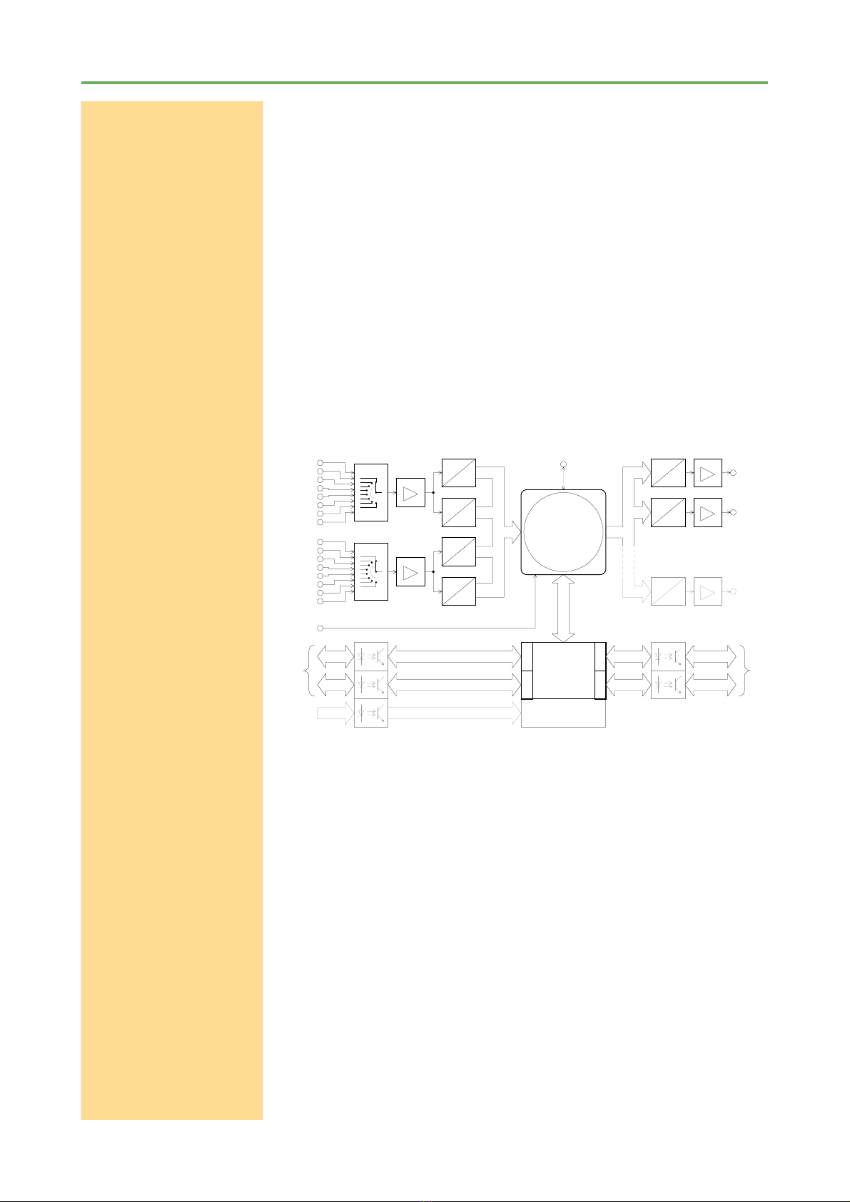
The ADwin-Gold system is equipped with analog and digital inputs and outputs,
a fast processor (32 bit floating point signal processor) and a local RAM. The
processor is responsible for the whole real-time processing in the system. The
applications are running independent of the PC and its workload.
The processor of the ADwin system processes each measurement value
instantaneously.In one cycle the status of the inputs can be acquired, the
status can be processed by the help of any mathematical functions, and the
system can react to the results, even at very fast process cycle times of some
microseconds. Here we have a perfect and logical work sharing: On the PC a
program is running for visualizing of data, for input and operation of the
processes, together with access to networks and data bases, while on the
processor of the ADwin system all tasks which require real-time, are executed
at the same time.
The real-time operating system for the DSP of the ADwin system has been
optimized to reach the fastest response times possible. It manages parallel
processes in a multitasking manner. Low priority processes are managed by
time slicing. High priority processes interrupt all low priority processes and are
instantaneously and completely executed. High priority processes are executed
as time-controlled or event-controlled processes (trigger/event input).
For the precise calling of high priority processes the built-in timer is responsible.
It has a resolution of 25 nanoseconds.The ADwin systems are characterized
by an extremely short response time of only 300 nanoseconds during the change
from a low priority to a high priority process. A continuously running communica-
tion process makes it possible to obtain a continuous data exchange between
the ADwin system and the PC even during applications in process. The comm-
unication has no influence on the real-time capability of the ADwin system,
nevertheless, it is possible to exchange data at any time.
With the real-time development tool ADbasic it is possible to create very easily
and quickly time-critical programs für ADwin systems. ADbasic is an integrated
development environment under Windows with possibilities for online
debugging. An habitual, easy-to-learn BASIC instruction syntax has been ex-
tended by many more functions, in order to get direct access to inputs and
outputs as well as by functions for process control and communication with the
PC.
Communication between ADwin system and PC
The ADwin system is connected to the PC via an ISA interface (optional PCI,
PCMCIA, USB, Ethernet). After power-up the ADwin system is booted from
the PC via this interface. Afterwards the ADwin operating system is waiting for
instructions from the PC which it will process.
2. ADwin System Features

ADwin-Gold Hardware Manual, Version 2.3 7
ADwin
Instructions
Software interfaces
There are two kinds of instructions: On the one hand instructions, which are
used to transfer data from the PC to the ADwin system, for instance „load
process“, „start process“ or „set parameters“, on the other hand instructions
which wait for a response from the ADwin system, for instance „read variables“
or „read data sets“. Both kinds of instructions are processed immediately by the
ADwin system - or respectively they are responding immediately. The ADwin
system never sends data to the PC without being asked to do so! The data
transfer to the PC is always a response to an instruction coming from the PC.
Thus, embedding the ADwin system into various programming languages and
standard software packages for measurements is easily made, because they
have only to be able to call functions and to process the return value.
Under Windows 95/98/NT/ME/2000/XP a DLL and an ActiceX interface are
available. Based on this the following drivers for user interfaces are also
available.
Visual-BASIC, Visual-C, C/C++, Delphi, VBA (Excel, Access, Word), TestPoint,
LabVIEW / LabWINDOWS, HP-VEE, InTouch, DIAdem, Matlab.
The easy, instruction-oriented communication with the ADwin system makes it
possible that several Windows programs can access the same ADwin system
at the same time. This is of course a great advantage when programs are
developed and installed.
Figure 2-1: Concept of the ADwin Systems
2.1 System Concept

8ADwin-Gold Hardware Manual, Version 2.3
ADwin
Processor and memory
Analog inputs
Analog outputs
Digital inputs and outputs
Trigger input (EVENT)
2.2 The ADwin-Gold System
The ADwin-Gold system is equipped with the digital 32 bit signal processor
ADSP 21062 (SHARC) from Analog Devices with floating point and integer
processing. It is responsible for the complete measurement data acquisition,
online processing, and signal output, and makes it possible to process
instantaneously sample rates of up to several 100 kHz.
The on-chip memory with 256 kB has a very short access time of 25 ns and
is large enough to hold the complete ADwin operating system, the ADbasic
processes and all variables.
In order to get maximum access times, all inputs and outputs are memory-
mapped in the external memory section of the DSP. For buffering larger quantities
of data the DSP uses an external memory (DRAM) of 4 MB (optional 16 MB or
32 MB).
The system has 16 analog inputs with BNC sockets, which are divided into
two groups and in each group is connected to one multiplexer. These two
outputs are optionally converted by a 12-bit or 16-bit analog-to-digital converter
(ADC), (see Figure: Bock diagram ADwin-Gold ). With the 12-bit ADCs it is
possible to sample very fast with the 16-bit ADCs highly accurately.
The standard version of the ADwin-Gold system is equipped with two (optio-
nal eight) analog outputs with an output voltage range of -10 to +10 Volt and
a 16-bit resolution. You can synchronize the output of the voltage of all DACs
per software.
In order to smooth the output signal, it passes through a low-pass filter with a
cut-off frequency of fc= 300 kHz.
32 digital inputs or outputs are available on two 25-pin D-Sub connectors.
They can be programmed in groups of eight as inputs or outputs. The inputs or
outputs are TTL-compatible.
ADwin-Gold has a trigger input (EVENT, see also chapter 5.2 „Digital Inputs
and Outputs“). Processes can be triggered by a signal and are completely
processed afterwards. (see ADbasic manual, chapter: Structure of the ADbasic
Program).
four 32 bit counter
16 bit, 10µs
16 bit, 10µs
12 bit, 0.8µs
12 bit, 0.8µs
A
D
A
D
A
D
A
D
MUX
MUX
IN 1
IN 3
IN 5
IN 7
IN 9
IN 11
IN 13
IN 15
IN 2
IN 4
IN 6
IN 8
IN 10
IN 12
IN 14
IN 16
D
A
SHARC
™
ADSP 21062
from Analog Devices
with 4/16/32 MByte
external DRAM
D
A
16bit
16bit
OUT 1
OUT 2
32 digital I/Os,
programmable
as in- or outputs
8
I/O
8
I/O
8
I/O
8
I/O
CONN. 1
(DIGITAL IN)
CONN. 2
(DIGITAL OUT)
to PC
EVENT
PGA
G = 1, 2, 4, 8
+
-
PGA
G = 1, 2, 4, 8
+
-
D
A
16bit
OUT 8
. . . . .
. . . . .
8 bit8 bit
8 bit8 bit
8 bit
8 bit
OP
+
-
OP
+
-
OP
+
-
. . . . .
8 bit
8 bit
Note: shaded components are optional.
A/CLK
B/DIR
CLR/L
Figure 2-2: Block diagram ADwin-Gold
2.2 The ADwin-Gold System

ADwin-Gold Hardware Manual, Version 2.3 9
ADwin
ADlink-ISA board
Standard delivery
ADbasic
The ADlink ISA board is installed in an ISA slot of the PC. This is the connection
via PC or notebook to the ADwin-Gold. The ADlink cable transfers data from
the ADlink ISA board to the ADwin-Gold.It has 9-pin D-Sub connectors and it
is shielded on both ends. If requested we will deliver an ADlink cable which is
shielded on one end (optically isolated).
The supplied 3-pin cable is used for the power supply and the earth connection
from the ADwin-Gold to the PC.
Due to technical reasons, pin number 5 has been removed from the
subminiature connector.
The standard delivery items for the ADwin-Gold system:
– the ADwin-Gold system
– the ADlink ISA board for installation into the PC
– the 3-pin connecting cable for power supply
– the ADlink cable, 9-pin data connecting cable, length 2.0 m
– the ADwin CDROM
– the manual „Driver Installation“
– this hardware manual
2.2.1 Further Interfaces
In addition to the ADlink board, the following items are available:
– Gold-PCI: board for installation into a PCI slot (replaces the ADlink-ISA
board), in combination with an ADpcmcia link adapter
–ADpcmcia: link adapter for connection to a notebook, with ADlink cable
–Gold-USB-Set: external USB adapter, with connecting cables
–Gold-ENET-Set: interface for the connection to the Ethernet, with connecting
cables
2.2.2 Options (no later upgrading possible)
The following options are available:
–Gold-DA: 6 additional analog outputs, 16-bit DACs
–Gold-CO1: counter option with four 32 bit counters, which can optionally be
used for period width measurement, as impulse counters or as up/down
counters with clock/direction or four edge evaluation for quadrature encoders
–Gold-opt: optical isolation of the digital inputs/outputs
–Gold-G-MEM-16/32: external memory with 16 MB/32 MB instead of 4 MB
–Gold-G-MEM-512k: internal CPU memory with 512 kB instead of 256 kB
–Gold-Boot: Flash-EPROM bootloader for stand-alone operation without PC
–Gold-Mount: kit for installation of the ADwin-Gold system on a DIN rail
All additional options can be combined with each other.
2.2.3 Accessories
–ADbasic, real-time development tool for all ADwin systems
–ADwin-Gold-pow: external power supply (necessary for notebook operation)
–Gold-cable-5: ADlink cable, length 5 meters
–ADlink cable which is shielded on only one end, length 2m / 5 m
– connector for the external power supply
2.2 The ADwin-Gold System

10 ADwin-Gold Hardware Manual, Version 2.3
ADwin
Earth protection
Excluding transient
currents
BNC cables
Ambient temperature
3. Operating Environment
The ADwin-Gold electronic is installed in a closed aluminum enclosure and it
is only allowed to operate it in this enclosure. (Exeption: Calibration, see chapter
with the same name). With the necessary accessories the system can be
operated in 19-inch-enclosures or as a mobile system (e.g. in cars). See also
chapter 2.2.2 „Options“).
The ADwin-Gold device must be earth-protected, in order to
– build a ground reference point for the electronic
– to conduct interferences to earth.
Connect the GND socket, which is internally connected with the ground
reference point and the aluminum enclosure, via a short low-impedance solid-
type cable to the central earth connection point of your device.
The 3-pin power supply cable is the galvanic connection between the PC and
the ADwin-Gold.
The data lines of the ADlink cable are optically isolated by opto-couplers. When
using an external power supply with is fully isolated from earth the PC can be
completely optically isolated from the ADwin-Gold.
The ADwin-Gold-opt module has optically isolated digital inputs and outputs.
Transient currents, which are conducted via the aluminum enclosure or the
shielding of the ADlink cable, have an influence on the measurement signal.
You may reduce these transient currents, by ordering (on request) the ADlink
cable shielded on one end only.
Please, make sure that the shielding is not reduced, for instance by taking
measures for bleeding off interferences, such as connecting the shielding to
the enclosure just before entering it. The more frequently you earth the shielding
on its way to the machine the better the shielding will be.
Use cables with shielding on both ends for signal lines.
Here too, you should reduce the bleeding off of interferences via the ADwin-
Gold aluminum enclosure by using screen clips.
The shielding of BNC cables is normally used as differential ground and looses
therefore the shielding effect. So BNC cables are influenced by interferences
when differential measurements are executed. For signal and data transfer
outside of an enclosure it is necessary to use twisted pair data transfer cables,
whose channels are shielded, too.
The ADwin-Gold is operated with a protection low voltage of 10 to 18 Volts
and is not life-threatening. For operation with an external power supply, the
instructions of the manufacturer applies.
The ADwin-Gold is designed for operation in dry rooms with a room temperature
of +5 °C ... +50 °C and a relative humidity of 0 ... 80 % (see chapter 13: Technical
Data).
The temperature of the chassis must not exceed +60 °C, even under extreme
operating conditions - e.g. in an enclosure or if the system is exposed to the
sun for a longer period of time. You risk damages at the device or not-defined
data (values) are output which can cause damages at your measurement device
under unfavorable circumstances.
3. Operating Environment

ADwin-Gold Hardware Manual, Version 2.3 11
ADwin
4. Initialization of the Hardware
If you start initializing do not connect any cables to the ADwin-Gold before
you have executed the following steps:
– carry out the driver installation at the PC or notebook
(see manual „ADwin Driver Installation“).
– connect the ADwin-Gold only with the PC or notebook (s.b.).
– Read chapter 5 “Inputs and Outputs“ in this manual.
– Now you may start connecting the inputs and outputs.
If your application requires an optical isolation between PC and ADwin-Gold
system please, use an external power supply unit and the ADlink cable with
shielding on one end only, which will be delivered separately.
Please pay attention that reliable power soucre is supplied.
This concerns the PC (standard delivery). Otherwise also the external power
supply, if operated in a car, the battery voltage.
If using current-limiting power supplies, please pay attention to the fact, that
after power-up the current demand can be a multiple of the idle current. More
detailed information can be found in the Technical Data.
In case of a power failure ...
– all data which have not been saved are lost. Not-defined data (values) can
under unfavorable circumstances cause damages to other equipments.
– the input resistance at the analog inputs will get into the status of low-
impedance, so that damages may occur at the ADwin-Gold system and
other connected devices (see also annex A-1 „Technical Data). Therefore
avoid absolutely connecting and operating the analog outputs when the
ADwin-Gold system is not powered up.
If you have completed the installation of the ADwin drivers and the configurations
in the ADbasic menue Options Compiler, than connect the ADLink cable
and the power supply cable.
In order to avoid switching off the system inadvertently, the switch is equipped
with a blocking device. Pull the switch a little bit, than pull it into the direction
„Power“. Now the device is switched on and the green LED lights up.
Start ADbasic and boot the ADwin system by clicking on the boot button „B“.
The display in the status line: „ADwin is booted“ shows that the operating
system has been loaded appropriately and that via ADbasic the ADwin system
has been connected. At the same time the flashing of the green LED at the
ADwin-Gold shows that it is ready for operation.
Programming the ADwin systems is described more detailed in the ADbasic
manual.
Start with the programming examples in the ADbasic Tutorial.
Providing the power
supply
Connection
Power-up
Booting
Programming
L
4. Initialization of the Hardware

12 ADwin-Gold Hardware Manual, Version 2.3
ADwin
Standard instructions
5. Inputs and Outputs
All inputs and outputs may only be operated according to the specifications
given (s. annex A-1 „Technical Data“). In case of doubt, ask the manufacturer
of the device, to which you want to connect the ADwin-Gold system.
Please avoid connecting and operating at the analog inputs when the ADwin-
Gold system is switched off. In this case the input resistance can get in the
status of low impedance at the analog inputs, so that damages at the ADwin-
Gold and at other connected devices may occur, (see also annex A-1:
„Technical Data, Analog Inputs, Overvoltage - maximum permissible current).
For fast and easy programming there are standard instructions available in the
compiler ADbasic, which enable a user to easily measure or output data (see
also ADbasic manual). Use other instructions only if extremely time-critical or
special tasks require to do so.
More detailed information about the analog as well as the digital inputs and
outputs can be found in the following chapters.
The pin assignments of CONN.1 and CONN.2 can be found in chapter 5.3.
5. Inputs and Outputs
IN 1 IN 3 IN 5 IN 7 IN 9 IN 11 IN 13 IN 15 OUT 1 OUT 3
IN 2 IN 4 IN 6 IN 8 IN 10 IN 12 IN 14 IN 16 OUT 2 OUT 4
CONN. 1 (DIGITAL IN)
CONN. 2 (DIGITAL OUT)
LINKPOWER
GND
CONN. 3
CONN. 4
ADwin-GOLD
analog
inputs
analog
outputs
power-
supply
LINK-
connector
GND-
connector
digital
inputs/outputs
additional
inputs/outputs
Figure 5-1: Schematic of ADwin-Gold

ADwin-Gold Hardware Manual, Version 2.3 13
ADwin
Power Supply
The power supply connection of the ADwin-Gold with 12 V (see Annex,
„Technical Data“), is made via the built-in connector, at left next to the power
switch or above the GND socket (see picture 5-1). Connect there the 3-pin
subminiature connector. For the pin assignment see the following picture:
If you operate the ADwin-Gold together with a PC, the system can get its
power supply by using the power-connector of the link adapter.
For using the system with an external power supply unit you need the subminia-
ture connector described above of the series 712, with the article number:
2 99-0406-00-03. The connector is provided by
Franz Binder GmbH + Co. elektrische Bauelemente KG
Rötelstrasse 27
D-74172 Neckarsulm
Tel.: +49 - 7132 - 325 -0
www.binder-connector.de
When using the system with a notebook, power has to be supplied by a sepa-
rate power supply. Please pay attention to the fact that it is sufficiently
dimensioned.
+9...18VPE
GND
1
2
3
Figure 5-2: Power supply connector (male)
Power Supply

14 ADwin-Gold Hardware Manual, Version 2.3
ADwin
Differential
Multiplexer
16-bit and 12-bit
measurements
ADC instruction
L
L
5.1 Analog Inputs and Outputs
In order to operate the system without any interferences, isolated BNC
connectors are necessary. Otherwise there will be the danger of damages
caused by ESD or short circuits at the inputs. This will be the case when using
not isolated BNC T-pieces.
The ADwin-Gold device has to be connected to earth, in order to execute
measurement tasks without any interferences. Connect the GND socket via a
low-impedance solid-type cable with the central earth connection point of your
device.
The power supply from the ADlink or ADlink-PCI board also connects the earth
of the ADwin-Gold with the earth of the PC. If you do not operate the PC and
the ADwin-Gold system in the same place, you should not use the power
supplied by the PC but an external power supply unit which if fully earth-free,
in order to avoid influences by different ground reference potentials.
In addition to the description of the inputs and outputs you will find notes below
for the conversion of digits into voltage values and for the input settings of the
analog inputs (differential / single-ended).
5.1.1 Inputs
The default setting of the analog inputs is differential (see chapter 5.1.4). The
voltage difference between positive and negative input (inner and outer conducter
of the BNC socket) is measured.
The system has 16 analog inputs (IN1...IN16) with male BNC-sockets, which
are arranged in 2 rows. The inputs with odd numbers (upper row) are allocated
to multiplexer 1 (and ADC 1), those with even numbers (lower row) to multiple-
xer 2 (and ADC 2).
You can convert the signals at the multiplexer outputs optionally with a 12-bit or
a 16-bit analog-to-digital-converter (ADC), (see figure 2-2 „Schematic of the
ADwin-Gold). You are measuring with
•the 12-bit ADC very fast (max. 0.8 µs, resolution 4.8828 mV),
•the 16-bit ADC very accurately (max. 8 µs, resolution 305 µV).
To simply execute a complete measurement with the ADC use the instructions
ADC() for the 16-bit ADC and ADC12() for the 12-bit ADC.
The ADC instructions consider for instance the settling of the multiplexer and
assure perfect measurements (see also ADbasic manual).
Please pay attention to a small internal resistance of the power supply unit (of
the input signals), because it may have influence on the measuring accuracy!
The measuring normally fits to the internal resistance of the ADwin-Gold
system; up from 10 Ω the internal resistance of the power supply unit causes a
linear error. Moreover, from about 1 kΩupwards the multiplexer settling time
extends. The waiting time defined in the standard instructions ADC() and
ADC12() shall then fall short, so that unprecise values are recalled. In this
case please use the instructions described in chapter 5.3.1.
5.1 Analog Inputs and Outputs

ADwin-Gold Hardware Manual, Version 2.3 15
ADwin
5.1.2 Outputs
The standard instruction DAC(
number
,
value
)checks each of the values
if it exceeds or falls below of the 16-bit value range (0...65,535). If the value is
in the 16-bit value range, the indicated value is output on the output
number
.
If it is not in the value range the maximum (65,535) or minimum (0) value is
output (see also ADbasic manual).
5.1.3 Calculation Basis
The voltage range of the ADwin-Gold at the analog inputs and outputs is
between –10 V to +10 V (bipolar 10 V).
The 65,536 (216) digits are allocated to the corresponding voltage ranges of
the ADCs and DACs insofar that
– 0 (zero) digits correspond to the maximum negative voltage and
– 65,535 digits correspond to the maximum positive voltage
The value for 65,536 digits, exactly 10 Volt, is just outside the measurement
range, so that you will get a maximum voltage value of 9.999695 Volt for the
16-bit conversion and a voltage value of 9.995117 Volt for the 12-bit conversion.
In the bipolar settings you will get a zero offset, called only offset in the following
text.
For the voltage range –10 V to +10 V applies: UOFF = –10 V
The ADwin-Gold has a programmable gain (PGA), with which you can amplify
the input voltage by the factors 1, 2, 4, and 8. At the same time the measurement
range gets smaller by the corresponding gain factor k (see Technical Data).
DAC instruction
L
Allocation of digits to
voltage
Zero offset
Gain factor
+10
-10
0 32768 65536
0
[V]
[Digit]
Figure 5-3: Zero offset in the standard setting of bipolar 10 Volt
5.1 Analog Inputs and Outputs

16 ADwin-Gold Hardware Manual, Version 2.3
ADwin
Please note that upon applications with k >1 the interference signals are
amplified respectively.
The quantization level (ULSB) is the smallest digitally displayable voltage
difference and is equivalent to the voltage of the least significant bit. A ULSB is
equivalent to the following formula:
- with 16-bit converters: 20 V / 216 = 305.175 µV,
- with 12-bit converters: 20 V / 212 = 4,882.8 µV.
In order to get the same bit allocation during measurements with the 12-bit
ADC and the 16-bit ADC, the converted value is returned left-aligned in one
word (16-bit) when using the 12-bit ADC. The lower four bits are always 0
(zero).
The 4,096 digits of the 12-bit ADC are mapped to the 65,536 digits of the 16-bit
ADC. Thus, 16 digits of the 16-bit ADC are equivalent to one digit of the 12-bit
ADC.
Therefore the following equations can be used for both ADC types.
Conversion Digit ''
''
'Voltage
For the DACs:
For the ADCs (12-bit and 16-bit):
Tolerance Ranges
Slight variations regarding the calculated values may be within the tolerance
range of the individual component. Two kinds of variations are possible (in LSB),
which are indicated in this hardware manual:
•The integral non-linearity (INL) defines the maximum deviation from the ide-
al straight line of the conversion characteristics curve, covering the whole
input voltage range.
•The differential non-linearity (DNL) defines the maximum deviation from the
ideal quantization level.
Least Significant Bit
ULSB
Allocation of the bits
DAC
ADC
INL
DNL
tiB 51 41 31 21 11 01 90 80 70 60 50 40 30 20 10 00
CDA-tib-21drowrewolehtnidengila-tfelassitnamtib-21 0000
CAD/CDA-tib-61drowrewolehtniassitnamtib-61
UDigitsUU
OUT LSB OFF
=·+
LSB
OFFOUT
U
UU
Digits −
=
LSB
OFFIN
U
UUk
Digits −⋅
=
k
UUDigits
UOFFLSB
IN
+⋅
=
5.1 Analog Inputs and Outputs

ADwin-Gold Hardware Manual, Version 2.3 17
ADwin
5.1.4 Input Circuitry of the Analog Inputs
At differential inputs (standard delivery) the voltage difference between inner
and outer conductor of the BNC socket is acquired.
At „single ended“ inputs all outer conductors of the BNC sockets are connected
via jumper Jx with the common ground (GND-connection).
The ADwin-Gold is delivered with the jumper setting for differential inputs, that
means the jumpers (Jx) are only plugged into one of the two pins. For the
„single-ended“ setting you have to close the corresponding jumper, that means
to connect both pins. The following picture of the main printed circuit board
shows where you can find the corresponding jumpers. The number added to
the „J“ corresponds to the number of the analog inputs.
Proceed as follows:
–You open the chassis by unscrewing the Allen screws at both sides and
remove the bottom part. Pull of very carefully and softly the attached printed
circuit board off the main printed circuit board.
–After replugging the jumper/s put the printed circuit board/s again back to the
analog printed circuit board. Please, pay attention to the fact that all pins of
the pin connectors are plugged into the socket strips in the right order.
–Close the chassis and tighten the Allen screws.
Jumper (Jx)
Open the chassis
12 Bit ADC-2
LTC1410
16 Bit ADC-2
LTC1605
12 Bit ADC-1
LTC1410
16 Bit ADC-1
LTC1605
DAC-1
DAC712
DAC-2
DAC712
INA-1
PGA206
INA-2
PGA206
OPA-1
OPA2131
J15
J7
J9
J5 J11
J3
J16 J14
J13
J12
J10
J8
J6
J4
J2
J1
P11 P12 P9 P10
P7 P8 P5 P6
P1P2
P3
OPA27
LS175 LS175
OPA27
LS125ALS14
721
836
8921 721
836
721
836
F32 ALS14
LS125
OFF GAIN
OFF GAIN
OFFGAIN
OFFGAIN
OFF GAIN
OFF GAIN
OPA
2132
ALS175
DC-DC-converter
LM399
MUX-1
ADG407
MUX-2
ADG407
ADwGLD11
P4
Buffer DAC-1 & -2
BNC-
connector
IN x
330k
330k
InAmp
+
-
to
ADC
J x
MUX
PGA
G = 1, 2, 4, 8
+
-
GND
Figure 5-4: Jumper position on the analog printed circuit board
5.1 Analog Inputs and Outputs

18 ADwin-Gold Hardware Manual, Version 2.3
ADwin
5.2 Digital Inputs and Outputs
32 digital inputs and outputs (abbreviation: DIO) are available on two 25-pin
D-SUB connections (see picture below). They are programmable in groups of
eight as inputs or outputs.
The digital inputs and outputs are TTL-compatible and not protected against
overvoltage.
Do not use connections marked as „reserved“. They are planned for upcoming
changes and expansions and can cause damages to your system if you do not
pay attention to this fact.
The ADwin-Gold is equipped with an external trigger input (EVENT). With this
trigger input processes are triggered by an external signal (trigger) with rising
edge and can completely and immediately be processed. (see ADbasic manual,
chapter „Structure of an ADbasic-Program“).
After power-up of the device, all connections are configured as inputs.
The instruction:
CONF_DIO(12)
configures DIO 0...DIO 15 as digital inputs and DIO 16...DIO 31 as digital
outputs (see pin assignment below).
Only in this configuration will you be able to totally access the inputs and outputs
wit the instructions
–DIGIN; DIGIN_WORD
–DIGOUT_WORD; SET_DIGOUT; CLEAR_DIGOUT
About programming under other configurations the following chapter will give
you more detailed information: chapter 5.3.2 „Time-Critical Tasks / Digital In-
puts and Outputs“), (see also ADbasic manual and ADbasic tutorial).
Trigger input (EVENT)
Power-up configuration
CONF_DIO(12)
L
CONN. 1
13121110987654321
252423222120191817161514
DIGIN-00
DIGIN-02
DIGIN-04
DIGIN-06
DIGIN-08
DIGIN-10
DIGIN-12
DIGIN-14
EVENT
GND
DIGIN-01
DIGIN-03
DIGIN-05
DIGIN-07
DIGIN-09
DIGIN-11
DIGIN-13
DIGIN-15
GND
reserved reserved
CONN. 2
12345678910111213
141516171819202122232425
GND
+5V (output, max. 0.1A)
DIGOUT-14
DIGOUT-12
DIGOUT-10
DIGOUT-08
DIGOUT-06
DIGOUT-04
DIGOUT-02
DIGOUT-00
GND
DIGOUT-15
DIGOUT-13
DIGOUT-11
DIGOUT-09
DIGOUT-07
DIGOUT-05
DIGOUT-03
DIGOUT-01
reserved reserved
Figure 5-5: Pin assignment under configuration with CONF_DIO(12)
Inputs / DIGIN
(male)
Outputs / DIGOUT
(female)
5.2 Digital Inputs and Outputs

ADwin-Gold Hardware Manual, Version 2.3 19
ADwin
5.3 Time-Critical Tasks
For extremely time-critical tasks you can use instructions with which you have
direct access to the control and data registers of the ADC and DAC (see
ADbasic manual). These registers can be found in the memory address area
of the ADSP (memory mapped). These instructions also allow to optimize the
program structure (s.b.).
Contrary to the standard instructions ADC(), ADC12() and DAC()the instruc-
tions for direct access do not have any test routines. Before you use them
we recommend to learn more about time sequences, progam structures and
functions sequences in an ADC.
5.3.1 Analog Inputs and Outputs
The standard instructions ADC() and ADC12() consist of a sequence of several
instructions (see below). They need a certain time for execution.
SET_MUX()
... ‘wait for settling time
START_CONV()
WAIT_EOC() ‘wait for end of conversion
READ_ADC() or READ_ADC12()
You can use (or extend) the waiting times wasted in the standard instructions
for other purposes by using the individual instructions. If you apply these
instructions skilfully you may be able to execute faster measurements.
It is important to set the START_CONV() instruction in a sufficient time-delay
from the SET_MUX() instruction, in order to consider the multiplexer settling
time (see also ADbasic manual, „Instruction Reference“).
Use the waiting times for instance for arithmetic operations and save CPU
time:
– Settling time of the multiplexer: At a maximum voltage jump of 20 Volt it is
6.5 µs (max.) for the 16-bit ADC and 1.5 µs for the 12-bit ADC.
– Conversion time of the ADCs: It is 0.8 µs for the 12-bit ADC and 8 µs for the
16-bit ADC.
Direct Register Access
A measurement can be executed very fast, when you directly access the control
and data registers of the ADC.
If you have made sure that at the analog outputs the values are within the range
limits, you can write very quickly into one or more DAC registers with direct
access to the hardware registers, and you can synchronously start the output
(see ADbasic manual).
The hardware addresses for the direct access to the control and data registers
are described on the following pages.
ADC() and ADC12()
Program structure
ADC
DAC
5.3 Time-Critical Tasks

20 ADwin-Gold Hardware Manual, Version 2.3
ADwin
sserddA
]XEH[ noitcnuF tiB stnemmoC
61-13 01-51 9 8 7 6 5 4 3 2 1 0
00000402
51,...,5,3,1slennahc:1#-XUMtes - - -------n n n ,lamiced7...0=yranib"nnn"
1+nnn=.hcdetceles
61,...,6,4,2slennahc:2#-XUMtes - - ----n n n--- ,lamiced7...0=yranib"nnn"
)1+nnn(2=.hcdetceles
1#-AGPniag----
gg------ ,lamiced3...0=yranib"gg"
2=niagdetceles
gg
2#-AGPniag--gg--------
01000402
)tib-61(1#-CDA:noisrevnoctrats - - -------1-s
noisrevnoctrats:0=s
tceffeon:1=s
)tib-61(2#-CDA:noisrevnoctrats - - -------1
s-
)tib-21(1#-CDA:noisrevnoctrats - - ------s1--
)tib-21(2#-CDA:noisrevnoctrats - - -----s- 1--
02000402
)tib-61(1#-CDA:sutatsCOE - - ---------e
noisrevnocfodne:0=e
gninnursinoisrevnoc:1=e
)tib-61(2#-CDA:sutatsCOE - - --------e-
)tib-21(1#-CDA:sutatsCOE - - ------e---
)tib-21(2#-CDA:sutatsCOE - - -----e----
03000402)tib-61(1#-CDA:retsigertuodaer-x x x x x x x x x x x
noisrevnocfotluser:x
04000402)tib-61(2#-CDA:retsigertuodaer-x x x x x x x x x x x
03100402)tib-21(1#-CDA:retsigertuodaer-x x x x x x x0000
04100402)tib-21(2#-CDA:retsigertuodaer-x x x x x x x0000
00100402 :noisrevnoctratsdnaretsigertuodaer
)tib-61(1#-CDA - x x x x x x x x x x x
01100402 :noisrevnoctratsdnaretsigertuodaer
)tib-61(2#-CDA - x x x x x x x x x x x
02100402 :noisrevnoctratsdnaretsigertuodaer
)tib-21(1#-CDA - x x x x x x x x x x x
0D100402 :noisrevnoctratsdnaretsigertuodaer
)tib-21(2#-CDA - x x x x x x x x x x x
Table 5-1: Hardware addresses of the control and data registers for the ADC
5.3 Time-Critical Tasks
Table of contents
Other Jäger Control System manuals
Popular Control System manuals by other brands

Franke
Franke DVS SH07-020 Installation & operating instructions

Fly Sky
Fly Sky FS-i6 instruction manual

isel automation
isel automation PSPCI user manual

resideo
resideo SmartValve SV9410 installation instructions

btsr
btsr ULTRAFEEDER operating manual

heat-timer
heat-timer ETV Platinum Plus Installation and operation manual