manuals.online logo
Brands
  1. Home
  2. •
  3. Brands
  4. •
  5. Exsys
  6. •
  7. Cables And Connectors
  8. •
  9. Exsys EX-1311-2 User manual

Exsys EX-1311-2 User manual

65
Die EX-1311-2 ist ein Modul zur Umsetzung von USB 2.0 auf eine S-232 Schnittstelle mit
FIFO 16C550 Port für den Anschluss von High Speed Seriellen S-232 Peripherie Geräten
(z.B. Modem, Plotter usw.). Die EX-1311-2 ist mit einem USB 2.0 A-Stecker zum Anschluss an
den PC und einem S-232 seriellen 9 Pin Stecker ausgestattet. Das USB Modul ist Hot Plug &
Play fähig. Für die Einstellungen der I/O Adressen und Interrupts sind keine Jumper und Ein-
stellungen notwendig, da die Einstellungen automatisch vom System BIOS und bei der Installa-
tion des Betriebssystems vorgenommen werden.
Kompatibilität: USB 1.1 & 2.0
Betriebssysteme: Windows 9.x/ ME/ 2000/ XP/ Vista/ 7/ 8.x/ 10/ Server 20xx/ Linux/ MAC
Anschlüsse: 1x USB 2.0 A-Stecker, 1x 9 Pin Stecker Seriell S-232
Lieferumfang: EX-1311-2, Treiber CD, Anleitung
Zertifikate:
1
BESCH EIBUNG & TECHNISCHE DATEN
AUFBAU
Anleitung
Vers. 1.0 / 01.11.17
EX-1311-2
ANSCHLÜSSE & STATUS LED‘S
USB 2.0 A-Stecker
zum Anschluss an PC
S1: 9 Pin Stecker Seriell S-232
2x Sechskantmuttern
9 Pin Stecker Seriell S-232
Pin Signal Pin Signal
1DCD 6DS
2XD 7TS
3TXD 8CTS
4DT 9I
5GND
DB 9M Verdrahtung S-232
DB9 (EX-1311-2) S-232 (Endgerät)
1DCD 1DCD
2XD 2XD
3TXD 3TXD
4DT 4DT
5GND 5GND
6DS 6DS
7TS 7TS
8CTS 8CTS
S-232 Anschlussbelegung:
HA DWA E INSTALLATION
Because there are large differences between PC’s, we can give you only a general installation
guide for the EX-1311-2. Please refer your computers reference manual whenever in doubt.
1. Connect the EX-1311-2 USB to the USB A-Port at the your PC.
2. If you would like to screw the serial cable to the 9 Pin connector of the EX-1311-2, then
unscrew the screws (see Picture 1) and screw the supplied hexagon nuts into the holes on
the EX-1311-2 (see Picture 2). Now you can attach the serial cable to the EX-1311-2.
CLEANING
For cleaning please use only a dry fluff less cloth and remove the dirt with gently pressure. In
the area of the connectors please make sure that no fibres from the cloth remain in the connect-
ors. Attention! Never use a moist or wet cloth for cleaning!
CONNECTO S & STATUS LED‘S
USB A-Plug:
USB 2.0 A-Plug
Pin Signal Pin Signal
1VCC 3DATA+
2DATA- 4GND
Picture 1 Picture 2
emove the Screws Insert the Hexagon Nuts
3. When you are ready you can start your PC and continue with the point „Driver Installation“.
Status LED‘s:
XD
TXD
D IVE INSTALLATION
Windows
After the hardware installation Windows will recognize the device automatically and install the
drivers. If the driver shoul not be installed automatically, please insert the Driver CD into your
CD-om drive (e.g. Drive D:) and open the folder „USB_to_IO/FTDI“. Please select the folder
with your operating system and install the driver (see Picture). Follow the hardware assistant
and finish the installation. Important! estart your PC in any case after installing the drivers.
CHECK INSTALLED D IVE
Open the >Device manager<. Now you should see at „Ports (COM & LPT)“ and „USB-
Controller“ the following new entry:
If you see this or a similar information the device is installed correctly.
234
HA DWA E INSTALLATION
T EIBE INSTALLATION
Beachten Sie bitte die folgenden Installationshinweise. Da es große Unterschiede zwischen PC‘s
gibt, können wir Ihnen nur eine generelle Anleitung zum Einbau der EX-1311-2 geben. Bei Unklar-
heiten halten Sie sich bitte an die Bedienungsanleitung Ihres Computersystems.
1. Schließen Sie die EX-1311-2 an eine USB A-Buchse Ihres PC‘s an.
2. Falls Sie das serielle Kabel mit dem 9 Pin Anschluss der EX-1311-2 verschrauben möchte,
dann schrauben Sie nun die ändelschrauben heraus (siehe Abbildung 1) und schrauben Sie
hierfür die mitgelieferten Sechskantmuttern in die Löcher an der EX-1311-2 ein (siehe Abbil-
dung 2). Nun können Sie das serielle Kabel an der EX-1311-2 befestigen.
EINIGUNG
Windows
Nach Abschluss der Hardwareinstallation erkennt das Betriebssystem automatisch den Adapter
und installiert diesen! Falls die Treiber nicht automatisch installiert werden sollten, legen Sie
nun die Treiber CD in Ihr CD-OM Laufwerk (z.B. Laufwerk D:) ein und öffnen Sie den Ordner
„USB_to_IO/FTDI“. Nun wählen Sie den Ordner Ihres Betriebssystems aus und installieren Sie
die Treiber (siehe Abbildung). Folgen Sie den Installationsanweisungen und schließen Sie die
Installation ab. Wichtig! Starten Sie Ihren PC nach der Installation neu.
Zur einigung des Gerätes verwenden Sie bitte ausschließlich ein trockenes nicht faserndes
Tuch und entfernen Sie die Verschmutzung mit leichtem Druck. Im Bereich der Anschlüsse bitte
darauf Achten, dass keine Fasern des Tuchs in der Buchse hinterlassen werden. Verwenden
Sie bitte zu einigung in keinem Fall ein feuchtes oder nasses Tuch!
ANSCHLÜSSE & STATUS LED‘S
USB A-Stecker:
USB 2.0 A-Stecker
Pin Signal Pin Signal
1VCC 3DATA+
2DATA- 4GND
ÜBE P ÜFEN DES INSTALLIE TEN T EIBE
Öffnen Sie den >Geräte-Manager<. Jetzt müssten Sie unter „Anschlüsse (COM & LPT)“ und
unter „USB-Controller“ folgenden Eintrag sehen:
Ist dieser oder ein ähnlicher Eintrag vorhanden, ist die EX-1311-2 richtig installiert.
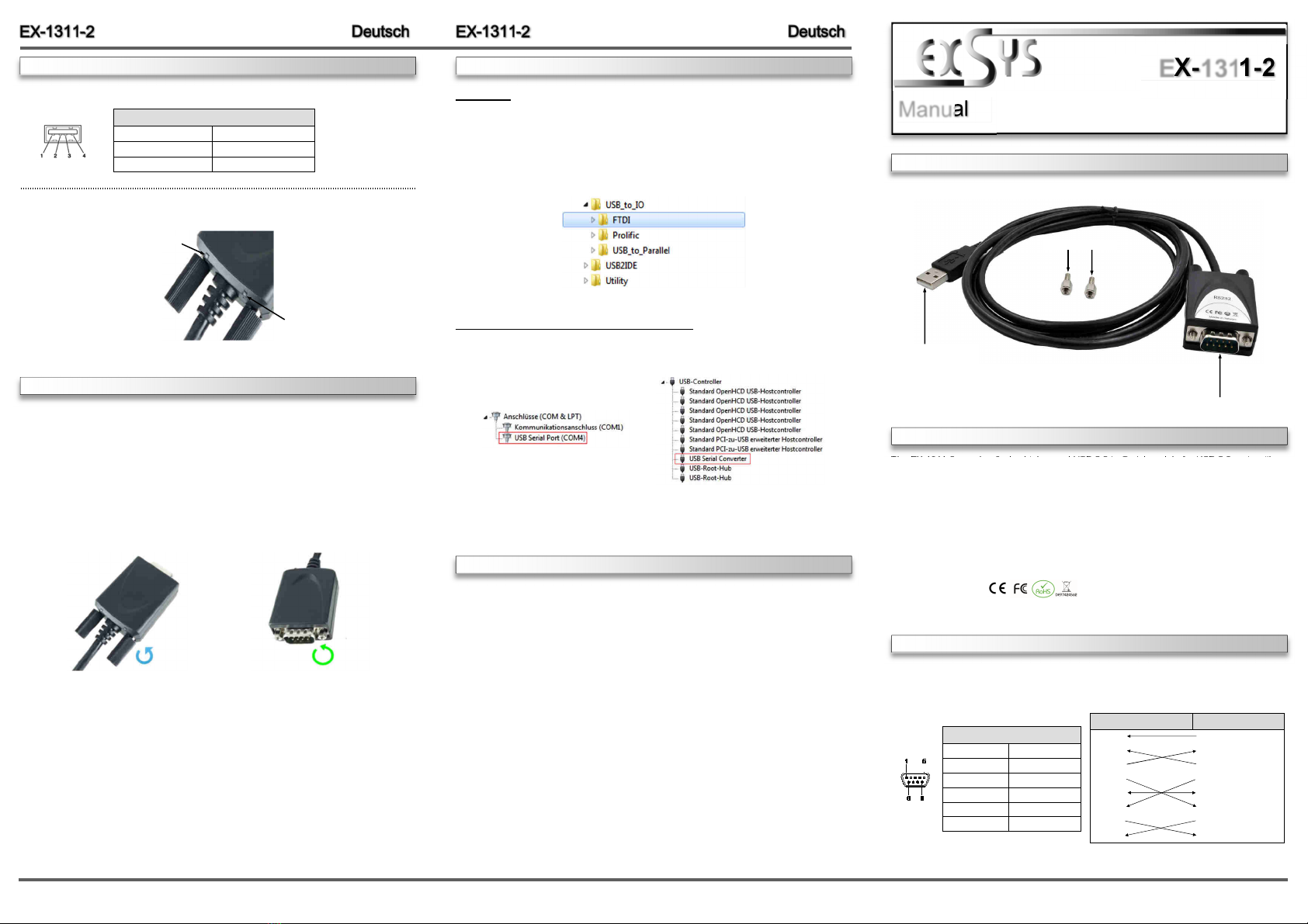
The EX-1311-2 are plug & play high-speed USB 2.0 to Serial module for USB 2.0 ports with up
to one S-232 9 pin connector. The EX-1311-2 provides one USB 2.0 A-Plug for connect to PC
and one 9 Pin serial S-232 connector. The USB to Serial module design utilizes the Chip-Set
FTDI with 16C550 UA T. It is not possible to change the address or I Q settings manually,
they will be obtained automatically by the operating system.
Compatibility: USB 1.1 & 2.0
Operating Systems: Windows 9.x/ ME/ 2000/ XP/ Vista/ 7/ 8.x/ 10/ Server 20xx/ Linux/ MAC
Connectors: 1x USB 2.0 A-Plug, 1x 9 Pin Serial S-232 Connector
Extent of delivery: EX-1311-2, Driver CD, Manual
Certificates:
DESC IPTION & TECHNICAL INFO MATION
LAYOUT
Manual
Vers. 1.0 / 01.11.17
EX-1311-2
CONNECTO S & STATUS LED‘S
USB 2.0 A-Plug
for connection to PC
S1: 9 Pin Serial S-232 Connector
2x Hexagon Nuts
9 Pin Serial S-232 Connector
Pin Signal Pin Signal
1DCD 6DS
2XD 7TS
3TXD 8CTS
4DT 9I
5GND
DB 9M S-232 Cable Wiring
DB9 (EX-1311-2) S-232 (Device)
1DCD 1DCD
2XD 2XD
3TXD 3TXD
4DT 4DT
5GND 5GND
6DS 6DS
7TS 7TS
8CTS 8CTS
S-232 Pin Assignments:
Abbildung 1 Abbildung 2
Entfernen der ändelschrauben Einsetzen der Sechskantmuttern
3. Jetzt können Sie Ihren PC starten und mit dem Punkt „Treiber Installation“ fortfahren.
Status LED‘s:
XD
TXD

Other Exsys Cables And Connectors manuals

Exsys EX-2311-2F User manual

Exsys

Exsys EX-2311-2F User manual

Exsys EX-1311-2-5V User manual

Exsys

Exsys EX-1311-2-5V User manual

Exsys EX-1305 User manual

Exsys

Exsys EX-1305 User manual

Exsys EX-1346IS User manual

Exsys

Exsys EX-1346IS User manual

Exsys EX-13002 Instruction manual

Exsys

Exsys EX-13002 Instruction manual

Exsys EX-1345 User manual

Exsys

Exsys EX-1345 User manual

Exsys EX-2311-2IS User manual

Exsys

Exsys EX-2311-2IS User manual

Exsys EX-13101 User manual

Exsys

Exsys EX-13101 User manual

Exsys EX-1311-2T User manual

Exsys

Exsys EX-1311-2T User manual

Exsys EX-1311-2FT User manual

Exsys

Exsys EX-1311-2FT User manual

Exsys EX-1324-37P User manual

Exsys

Exsys EX-1324-37P User manual

Exsys EX-23001 User manual

Exsys

Exsys EX-23001 User manual

Exsys EX-1311-2F User manual

Exsys

Exsys EX-1311-2F User manual

Exsys EX-1311-2F User manual

Exsys

Exsys EX-1311-2F User manual

Exsys EX-1311-2IS User manual

Exsys

Exsys EX-1311-2IS User manual

Exsys EX-13001 User manual

Exsys

Exsys EX-13001 User manual

Popular Cables And Connectors manuals by other brands

Staubli M220 Assembly instructions

Staubli

Staubli M220 Assembly instructions

PCB Piezotronics 009V15 Installation and operating manual

PCB Piezotronics

PCB Piezotronics 009V15 Installation and operating manual

LAPP MODE3 2.0 operating instructions

LAPP

LAPP MODE3 2.0 operating instructions

Staubli PerforMore Assembly instructions

Staubli

Staubli PerforMore Assembly instructions

Insignia NS-SBNC100P92 Quick setup guide

Insignia

Insignia NS-SBNC100P92 Quick setup guide

Radio Shack 1500652 user guide

Radio Shack

Radio Shack 1500652 user guide

rako RAK-LINK instruction manual

rako

rako RAK-LINK instruction manual

Tecnosystemi smart clima SCC300008 user manual

Tecnosystemi

Tecnosystemi smart clima SCC300008 user manual

Crestron TPS-CBL install guide

Crestron

Crestron TPS-CBL install guide

CORNING SST Installing a Wire Mesh Pulling Grip

CORNING

CORNING SST Installing a Wire Mesh Pulling Grip

Connect Research CBH1214 user manual

Connect Research

Connect Research CBH1214 user manual

Siemens SIMATIC NET IE RJ45 Plug PRO Assembly instructions

Siemens

Siemens SIMATIC NET IE RJ45 Plug PRO Assembly instructions

REED R5400 instruction manual

REED

REED R5400 instruction manual

Ophit DMD-H102 user manual

Ophit

Ophit DMD-H102 user manual

Splitvolt SPS C1-011 Quick start user guide

Splitvolt

Splitvolt SPS C1-011 Quick start user guide

NEUTRIK NAC3MX-W Operating & assembly instruction

NEUTRIK

NEUTRIK NAC3MX-W Operating & assembly instruction

CommScope HELIAX FiberFeed HTC1006 Series Installation guidelines

CommScope

CommScope HELIAX FiberFeed HTC1006 Series Installation guidelines

CORNING SRP-004-067 Service manual

CORNING

CORNING SRP-004-067 Service manual

manuals.online logo
manuals.online logoBrands
  • About & Mission
  • Contact us
  • Privacy Policy
  • Terms and Conditions

Copyright 2025 Manuals.Online. All Rights Reserved.