Exsys EX-1345 User manual

Because there are large differences between PC’s, we can give you only a general
installation guide. Please refer your computer’s reference manual whenever in doubt.
1. Connect the USB cable to the USB B-Port.
2. Now connect the other end from the USB cable (A-Plug) to the A-Port at your PC.
HARDWARE INSTALLATION
65
EX
EX
EX-
-
-1345
1345
1345
English
English
English
EX
EX
EX-
-
-1345
1345
1345
English
English
English
1
Die EX-1345 USB zu Parallel ist zur Umsetzung von USB auf Parallele Schnittstelle für
den Anschluss von Drucker geeignet. Wird im Betriebssystem Windows als „USB Dru-
cker Unterstützung“ installiert. Die EX-1345 ist Hot Plug & Play fähig. Für die Einstellun-
gen der I/O Adressen und Interrupts sind keine Jumper und Einstellungen notwendig.
Sie werden vom System und beim Installieren des Betriebssystems automatisch vorge-
nommen.
BESCHREIBUNG & TECHNISCHE DATEN
AUFBAU
Kompatibilität: USB 1.1 & 2.0
Betriebssysteme: Windows 2000/ XP/ Vista/ 7/ 8/ Server 2003/ MAC
Anschlüsse: 1x 25 Pin D-Sub Buchse, 1x USB B-Buchse
Lieferumfang: EX-1345, Treiber CD, Anleitung, USB Kabel
Zertifikate:
CE
CECE
CE / FCC / RoHS / WEEE DE97424562
DRIVER INSTALLATION
ANSCHLÜSSE
Windows 2000/ XP/ Server 2003
Windows will recognize a new “USB Parallel Device“ and open the hardware assistant.
Windows will recognize the device automatically and install it. Follow the hardware
assistant and finish the installation. Restart Windows in any case after installing the
drivers.
CHECK THE INSTALLED DRIVER
Click at Start<>Run< then enter “compmgmt.msc“ and click at >OK<. In the windows
that open select >Device Manager<. And open „Universal Serial Bus Controller“ you
should find the entry „USB Parallel Converter“. If you see this or similar entries the
module is installed correctly.
CHANGE PORT NUMBER
It is not possible to change the port number, because it would install as an “Printer support”
and thus there is no LPT port.
INSTALL THE PRINTER DEVICE
To install a printer please proceed with the following steps:
Click at >Start< >Settings< >Printer and Fax devices< >Add printer< >Next< >Local
printer<. Select one of the new ports “USB 001 or USB 002 (Virtual printer port for
USB)” to install a new printer to the module. Now follow the Hardware assistant to
complete the Installation of your printer.
Windows Vista/ 7/ 8
Windows will recognize a new “USB Parallel Device“ and open the hardware assistant.
Windows will recognize the device automatically and install it. Follow the hardware
assistant and finish the installation. Restart Windows in any case after installing the
drivers.
CHECK THE INSTALLED DRIVER
Click at the “Start Windows Logo< then enter “compmgmt.msc“ at the “search box”
and select it on the top under “Programs”. In the windows that open select >Device
Manager<. And open „USB Controller“ there you should find the entry „USB Parallel
Converter“. If you see this or similar entries the module is installed correctly.
CHANGE PORT NUMBER
It is not possible to change the port number, because it would install as an “Printer support”
and thus there is no LPT port.
Bedienungsanleitung
Bedienungsanleitung
Vers. 1.1 / 26.06.13
CONNECTORS
Pin Signal Pin Signal Pin Signal
1 STROBE 10 ACKNOWLEDGE 19 GROUND
2 DATA 0 11 BUSY 20 GROUND
3 DATA 1 12 PAPER EMPTY 21 GROUND
4 DATA 2 13 SELECT 22 GROUND
5 DATA 3 14 AUTO FEED 23 GROUND
6 DATA 4 15 ERROR 24 GROUND
7 DATA 5 16 INIT 25 GROUND
8 DATA 6 17 SELECT INPUT
9 DATA 7 18 GROUND
Parallel 25 Pin Buchse
DB 25F:
USB B-Connector:
USB 2.0 B-Connector:
Pin Signal Pin Signal
1 VCC 4 GND
2 DATA-
3 DATA+
Attention!
Never plug in with
force or in wrong
direction.
P1: 25 Pin D-SUB
Parallel Buchse
DRIVER INSTALLATION
INSTALL THE PRINTER DEVICE
To install a printer please proceed with the following steps:
Click at >Start< >Settings< >Printer and Fax devices< >Add printer< >Next< >Local
printer<. Select one of the new ports “USB 001 or USB 002 (Virtual printer port for
USB)” to install a new printer to the module. Now follow the Hardware assistant to
complete the Installation of your printer.

User Manual
User Manual
Vers. 1.1 / 26.06.13
2 3 4
EX
EX
EX-
-
-1345
1345
1345
Deutsch
Deutsch
Deutsch
EX
EX
EX-
-
-1345
1345
1345
Deutsch
Deutsch
Deutsch
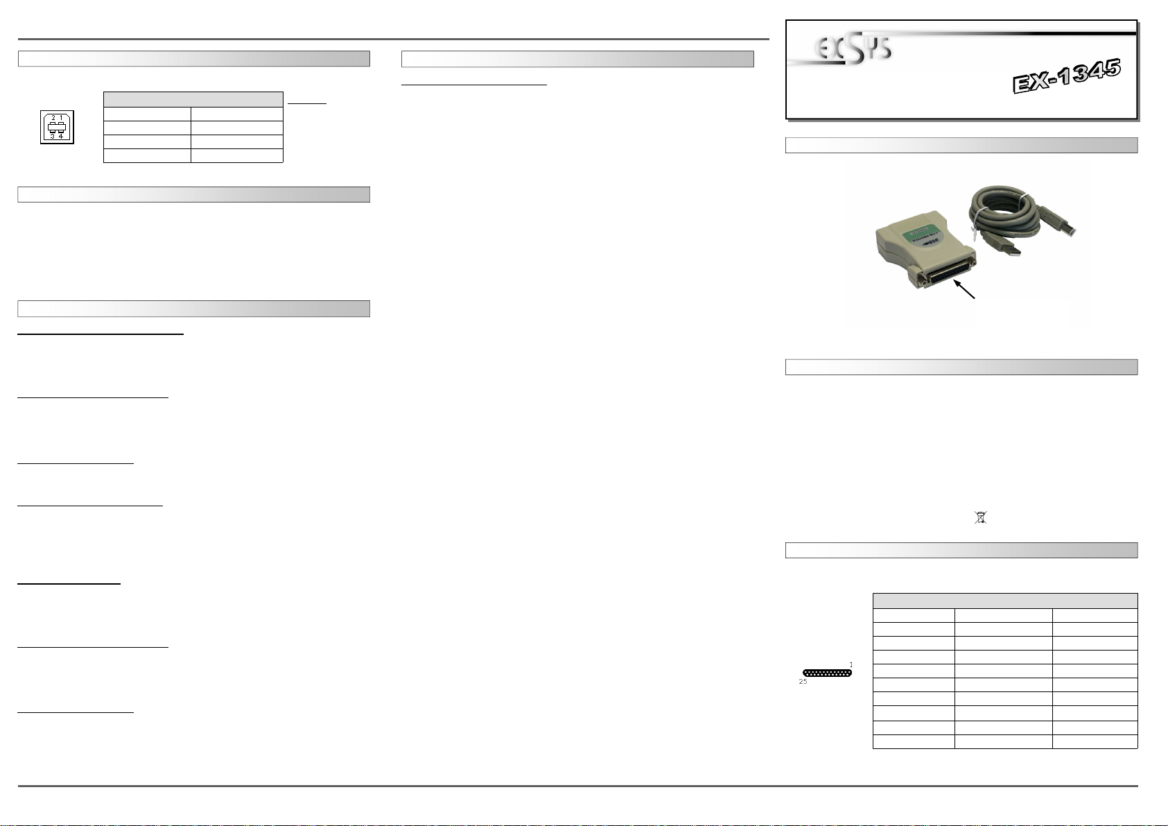
The EX-1345 are plug & play high-speed USB to Parallel modules for USB 1.1 and 2.0.
They provide 25 pin parallel ports for parallel devices and 1 USB uplink port for PC. The
USB to Parallel modules design utilizes the Chip-Set Prolific. It is not possible to change
the address or IRQ settings manually, they will be obtained automatically by the operat-
ing system. The USB to Parallel module will configure as “USB Parallel Converter”.
DESCRIPTION & TECNICAL INFORMATION
Compatibility: USB 1.1 & 2.0
Operating system:
Windows 2000/ XP/ Vista/ 7/ 8/ Server 2003/ MAC
Connectors: 1x 25 Pin female connector, 1x USB B-Port
Extent of delivery: EX-1345, Driver CD, Manual, USB Cable
Certificates:
CE
CECE
CE / FCC / RoHS / WEEE DE97424562
LAYOUT
CONNECTORS
HARDWARE INSTALLATION
Beachten Sie bitte die folgenden Installationshinweise. Da es große Unterschiede
zwischen PC‘s gibt, können wir Ihnen nur eine generelle Anleitung zum Einbau geben.
Bei Unklarheiten halten Sie sich bitte an die Bedienungsanleitung Ihres Computersys-
tems.
1. Verbinden Sie das mitgelieferte USB Kabel mit der USB B-Buchse.
2. Verbinden Sie nun das andere Ende (A-Stecker) des mitgelieferten USB Kabels mit
der A-Buchse an Ihrem PC.
TREIBER INSTALLATION
Windows 2000/ XP/ Server 2003
Windows erkennt automatisch eine neue “USB Parallel Device“ und Installiert diese.
Es werden keine Treiber benötigt da diese bereits im Windows integriert sind. Starten
sie anschließend den Rechner neu.
ÜBERPRÜFEN DES INSTALLIERTEN TREIBERS
Klicken Sie auf Start< >Ausführen< geben sie “compmgmt.msc“ ein und klicken sie
auf >OK<. Wählen sie nun >GeräteManager<. unter „Universeller Serieller Bus
Controller“ den Eintrag „USB Parallel Converter“ sehen. Wenn Sie diese oder ähnli-
che Einträge sehen, sind die USB Module korrekt installiert.
ÄNDERN DER PORT NUMMER
Dies ist nicht möglich da es sich um eine “USB-Druckerunterstützung“ handelt und somit
keine LPT Ports angeboten werden!
INSTALLATION DER DRUCKER
Um einen Drucker an die Module anzuschliessen gehen Sie folgendermaßen vor:
Klicken Sie auf >Start< >Systemsteuerung< >Drucker und Faxgeräte< >Drucker
hinzufügen< >Weiter< Lokaler Drucker<. Beim dem Windows Fenster mit der Aus-
wahl "Folgenden Anschluss verwenden“ wählen Sie dann z.B.:
USB 001 (Virtual printer port for USB) um einen Drucker an einen der Ports zu konfi-
gurieren. Folgen sie jetzt einfach dem Hardwareassistenten um die Installation ihres
Druckers abzuschliessen!
Windows Vista/ 7/ 8
Windows erkennt automatisch eine neue “USB Parallel Device“ und Installiert diese.
Es werden keine Treiber benötigt da diese bereits im Windows integriert sind. Starten
sie anschließend den Rechner neu.
ÜBERPRÜFEN DES INSTALLIERTEN TREIBERS
Klicken Sie auf das “Start Windows Logo“ und geben sie “compmgmt.msc“ in das
Feld >Suche Starten< ein und wählen sie den Eintrag compmgmt oben unter Pro-
gramme aus der Liste aus. Wählen sie nun >GeräteManager<. unter „USB Controller“
sollten sie den Eintrag „USB Parallel Converter“ sehen. Wenn Sie diese oder ähnliche
Einträge sehen, sind die USB Module korrekt installiert.
ÄNDERN DER PORT NUMMER
Dies ist nicht möglich da es sich um eine “USB-Druckerunterstützung“ handelt und somit
keine LPT Ports angeboten werden!
TREIBER INSTALLATION
INSTALLATION DER DRUCKER
Um einen Drucker an die Module anzuschliessen gehen Sie folgendermaßen vor:
Klicken Sie auf >Start Windows Logo< >Systemsteuerung< >Drucker< >Drucker
hinzufügen< >Weiter< Lokaler Drucker<. Beim dem Windows Fenster mit der Aus-
wahl "Folgenden Anschluss verwenden“ wählen Sie dann z.B.:
USB 001 (Virtual printer port for USB) um einen Drucker an einen der Ports zu konfi-
gurieren. Folgen sie jetzt einfach dem Hardwareassistenten um die Installation ihres
Druckers abzuschliessen!
ANSCHLÜSSE
USB B-Buchse:
USB 2.0 B-Buchse
Pin Signal Pin Signal
1 VCC 3 DATA+
2 DATA- 4 GND
Achtung!
Stecker nie umge-
kehrt oder mit
Gewalt einstecken.
P1: 25 pin female
parallel port
Pin Signal Pin Signal Pin Signal
1 STROBE 10 ACKNOWLEDGE 19 GROUND
2 DATA 0 11 BUSY 20 GROUND
3 DATA 1 12 PAPER EMPTY 21 GROUND
4 DATA 2 13 SELECT 22 GROUND
5 DATA 3 14 AUTO FEED 23 GROUND
6 DATA 4 15 ERROR 24 GROUND
7 DATA 5 16 INIT 25 GROUND
8 DATA 6 17 SELECT INPUT
9 DATA 7 18 GROUND
Parallel 25 Pin female connector
DB 25F:
Table of contents
Languages:
Other Exsys Cables And Connectors manuals

Exsys
Exsys EX-1311-2T User manual

Exsys
Exsys EX-2311-2IS User manual

Exsys
Exsys EX-2311-2F User manual

Exsys
Exsys EX-1311-2F User manual

Exsys
Exsys EX-1311-2-5V User manual

Exsys
Exsys EX-1311-2F User manual

Exsys
Exsys EX-1311-2IS User manual

Exsys
Exsys EX-13001 User manual

Exsys
Exsys EX-13002 Instruction manual

Exsys
Exsys EX-1305 User manual