manuals.online logo
Brands
  1. Home
  2. •
  3. Brands
  4. •
  5. Extreme Flight
  6. •
  7. Toy
  8. •
  9. Extreme Flight 78" EXTRA 300 ARF User manual

Extreme Flight 78" EXTRA 300 ARF User manual

125" EXTRA 300
ARF
Assembly Manual
Congratulations on your purc ase of t e new Extreme Flig t RC 125" Extra
300. T is airframe is t e culmination of several years of design, revision and
flig t testing, resulting in a top quality competition grade aircraft. T is
airframe comes ig ly prefabricated allowing one to assemble and fly t e
Extra wit minimal effort.
T e Extra 300 was designed to excel at IMAC and invitational sequence
flying. It is also a very capable 3D aircraft in t e ands of an experienced
pilot. T e Extra's fuselage as been stretc ed to t e maximum allowable limit
providing for an aircraft t at tracks extremely well and will certainly prove
itself a contender in t e upper classes of competition flying.
T is aircraft is intended for experienced pilots wit a t oroug knowledge of
giant scale aircraft power systems and radio/servo/linkage set-ups. As suc
t e assembly manual is brief and outlines t e important points t at must be
addressed t at are unique to t is airframe. Personal preference based on
previous experience will dictate finis ing details suc as radio/battery
installation, fuel tank c oice, installation and plumbing, grap ics c oices and
installation. If you are not experienced enoug to make t ese decisions I
ig ly recommend t at you start wit a smaller, less expensive aircraft in t e
30cc-50cc range to learn t e important basics of flying and maintaining
gasoline powered aircraft before stepping up to suc an expensive and
potentially dangerous aircraft.
Extreme Flig t RC, LTD. in no way accepts or assumes responsibility or
liability for any damage, destruction of property, injury or deat associated
wit t e use of t e final user assembled product. If you are not willing to
accept any and all responsibility for t e use of t is aircraft please return it to
t e place of purc ase immediately.
Wing assembly
(Please note t at we ig ly recommend t e use of 3 ultra torque servos for aileron
actuation. We did extensive testing using bot 2 and 3 servos and t e gain in roll and snap
performance using 3 servos is by far wort t e investment in additional servos and t e time
required to properly set t em up).
1. First I ig ly recommend t at you take a few minutes and go over all seams wit a
covering iron on a medium setting, paying special attention to stripes and areas w ere
covering overlaps.
2. T e ailerons use a unique pocket inge system. T ere are two rods t at act as t e inge
pins for t is system, one inserted at t e tip of t e wing, t e ot er t roug t e root. Use a
flat ead screw driver to back out t e t readed portion of t e rods and put a few drops of
blue Loctite on eac . Re-tig ten t e t readed portion into t e t readed insert. Make sure
to do t is for bot wings.
3. Next we'll install t e aileron control orns. It is imperative t at you pay close attention
during t is step. In order to provide t e proper linkage geometry eac set of aileron
control orns as a ole drilled in a different location to compensate for t e varying
t ickness of t e wing and aileron. T e picture below illustrates t e proper location of eac
set of orns.
4. Use a s arp obby blade to remove t e covering over t e slots at eac of t e 3 locations
w ere t e dual truss control orns will be installed. Place t e orns into t e base and
insert into t e slots in t e aileron. Trace around t e base wit a fine tipped felt marker.
5. Use a s arp obby blade to remove t e covering 1/16" inside t e line you ave traced so
t at t e fiberglass base plate will cover t e exposed edges and prevent t em from lifting.
6. Scuff t e portion of t e control orns t at will be glued into t e aileron wit sandpaper
to remove t e glossy s een and clean wit denatured alco ol. Mix up some 30 minute
epoxy (I prefer Mercury Ad esives 30 minute formula). Use a piece of pus rod or old
obby blade to fill t e slots in t e aileron wit epoxy. Coat t e entire area of t e orns t at
will insert into t e aileron and t e bottom of t e base plate wit epoxy. Insert t e orns
into t e slot and pus down until t ey are flus wit t e base plate. Use a paper towel
soaked wit denatured alco ol to remove t e excess epoxy. Insert a 3mm bolt t roug t e
oles in t e orn to insure proper alignment. Repeat t is process for t e remaining control
orns.
7. Use a s arp obby blade to remove t e covering at t e location of eac servo and seal
t e edges wit a ot trim iron. Take a few minutes and saturate all joints of t e servo
mounting trays wit CA.
8. Use t e manufacturer supplied ardware to mount t e servos in t eir proper location
wit t e servo s aft toward t e trailing edge of t e wing. You will need to use 1- 36", 1-
24", and 1-12" extension to get t e servo leads out of t e wing. We recommend t e use of a
1.5 inc aluminum servo arm. T read 2 ball links onto t e titanium pus rod and install
t e pus rod as s own in t e picture using t e supplied ardware. It will be necessary to
place a was er on eac side of t e ball link between t e brass ball and t e fiberglass control
orn to prevent binding.
9. It is ig ly recommended t at you use a servo programmer, Matc box or power
distribution unit to make sure all 3 servos work in unison. We use t e Hitec 7955s and
7950s in our aircraft in conjunction wit t e Hitec programmer and ave been able to get
t e servos matc ed perfectly wit very little current draw.
Elevator/stab assembly
10. Just as you did wit t e wings, take a few moments to go over all t e seams and stripes
wit a ot iron to ensure all edges are sealed.
11. Use a flat ead screw driver to back out t e t readed portion of t e inge pin rod at
t e root of t e elevator. Place a couple drops of blue Loctite on t e t reads and re-tig ten
t e inge pin rod. Repeat for t e ot er stab/elevator alf.
12. T ere are provisions to use 2 elevator servos per alf included wit t e Extra. We
ave found one ultra torque servo to be sufficient (Hitec 7955 or 7950, JR 8711 HV, Futaba
9156 or 9157). If using a single servo use t e servo mount furt est outboard on t e stab
and t e corresponding elevator orn slot.
13. Using t e same tec nique as wit t e aileron mount t e elevator control orn as
s own. All of t e elevator orns are identical.
14. Install your servo using t e manufacturer supplied mounting ardware wit t e
output s aft oriented toward t e trailing edge of t e stab. T read a ball link onto eac end
of t e t readed titanium pus rod and install using t e supplied ardware as s own in t e
picture. We use a 1.5 inc aluminum servo arm for elevator actuation. If setting up t e
Extra for precision aerobatics only we suggest using a 1 inc arm for better resolution.
Rudder preparation and installation
15. T is step is also very important-please pay close attention. T ere are 2 sets of control
orns provided for t e rudder. T e larger orn set is to be used if you intend to use a pull-
pull set-up wit t e rudder servos mounted inside t e fuselage under t e canopy. If using 4
elevator servos it is recommended t at you use t e pull-pull option to elp ac ieve proper
CG. A 5 inc servo arm is recommended for proper geometry.
T e smaller orns are to be used if you use a direct drive pus -pull linkage wit 2 servos
mounted in t e rear of t e fuselage. T is is t e preferred met od as it is muc easier to set
up and provides a more direct and powerful means of rudder actuation. T ese orns are
t e same as used for t e elevators.
16. Using t e same met ods as used previously wit t e ailerons and elevator, install t e
fiberglass rudder orns on eac side of t e rudder. T e rudder is inged using t e same
met od as wit t e ailerons and elevators. Place a few drops of blue Loctite on t e
t readed portion of t e rudder inge pin and insert into rudder. Tig ten using a flat ead
screwdriver. T e picture below s ows t e completed assembly using t e direct drive pus -
pull met od. We are using 2 inc servo arms. Please note t at t e output s aft is oriented
toward t e rear of t e aircraft. T is same set-up is to be repeated on t e ot er side of t e
fuselage. T e use of 2 ultra torque servos suc as t e Hitec 7950, JR 8711HV or Futaba
9157 is mandatory.
17. T ere are 2 additional plywood trays included to accommodate various pull-pull set-
ups. One tray allows t e use of up to 3 standard size ig torque servos ganged toget er.
T e additional ardware required for t is set-up is not included in t is kit. Also included
is a tray to allow t e use of a single Seiko industrial grade servo. T ese trays are tabbed to
glue into fuselage under t e canopy.
Fuselage assembly
18. Let's start by getting t e landing gear mounted. Use t e supplied 8mm bolts, nylon
insert lock nuts and was ers to mount t e carbon fiber landing gear to t e bottom of t e
fuselage. T e straig t portion of t e gear leg s ould be oriented toward t e front of t e
aircraft.
19. T e landing gear fairings add a nice scale touc to t e aircraft but are not necessary.
If you wis to use t em, slit t e supplied black neoprene tubing lengt wise wit a s arp
obby knife. Pus t e tubing onto t e rim of t e fairing and secure wit CA. Attac t e
fairing to t e gear wit "Goop" silicon glue. Alternately you can secure t em wit a small
screw as s own in t e p oto above.
20. Install t e supplied axles, w eels and pants onto t e carbon fiber landing gear.
21. Mounting t e engine is quite easy. T ere are laser inscribed reference marks on t e
front of t e engine mounting plate. W en looking at t e front of t e mounting plate t e
vertical line to t e rig t of t e center line s ould be used to allow for rig t t rust offset to
counter spiral slipstream effect. T e distance from t e face of t e engine mounting plate to
t e engine drive was er s ould be 8 1/8 inc es. Use standoffs to ac ieve t is lengt .
Here are a couple of p otos s owing t e installation of t e DA-170 in our Extra.
22. T ere are plywood tabs supplied for mounting your fuel tank. T ese are pus ed up
from inside t e pipe tunnel and s ould be secured wit epoxy. Due to t e wide range of
engines t at will be used a gas tank is not provided. We ave started making our own
tanks from 64 ounce juice bottles using brass fittings available from B&B Specialties.
Please see t e following picture s owing our ome made tank and installation.
23. T rottle servo installation and linkage set-up will depend on t e requirements of t e
engine you are using. As suc t ere are no provisions supplied for t e mounting of t e
t rottle servo.
24. Cowl mounting is very easy! T e cowl is secured wit 3 4mm screws. It is best to
insert t e longest of t e 3 screws into t e bottom of t e cowl and secure first, t en t e top 2
screws as s own. Be sure to use a was er and a generous amount of blue Loctite to prevent
t e screws from backing out.
25. T ere are 2 blind nuts pre-installed in t e rear bottom of t e fuselage for mounting t e
carbon fiber tail w eel assembly. Before installing t is assembly, file flat spots on t e tail
w eel wire so t at all set screws from t e various collars seat properly. Use a drop of blue
Loctite on eac setscrew.
26. Install t e tiller arm on t e bottom of t e rudder along wit t e supplied springs w ic
will steer t e tail w eel.
27. Secure t e stabs to t e fuselage wit t e supplied 3mm bolts and was ers, making sure
to use a generous amount of blue Loctite to prevent t e bolts from backing out.
28. Installation of batteries and radio equipment is up to t e end user and will depend on
t e equipment you c oose to use. T ere are four laser cut oles in t e fuselage t at will
accept t e JR PA004 Super Switc and various ot er units from ot er manufacturers.
29. T e wing is secured to t e fuselage using a combination of a 1/4-20 nylon bolt inserted
into t e wing from inside t e fuselage at t e rear of t e c ord and into t e pre-installed
blind nut in t e wing root and a 4mm bolt t at inserts into t e tongue t at protrudes from
t e wing. T is bolt is secured in t e fuselage using t e pre-installed blind nut.
T is completes t e assembly process for t e Extra. T e Center of gravity for t e Extra is
on t e center of t e wing tube. You may prefer it slig tly in front of or be ind t is position
depending on your flying style. One of t e easiest met ods to c eck CG on an aircraft of
t is size is to tie a t in rope around t e wing tube on eac side of t e fuselage. Slide t e
wings into position and install t e canopy. Lift t e aircraft using t e rope and adjust t e
position of your batteries and radio gear to ac ieve proper balance.
Please note: T e ig quality airfoiled carbon fiber landing gear is very lig tweig t and
plenty strong to andle normal landings. It will not andle side loads well. Be sure to
bleed off speed w en landing before making a turn to prevent from collapsing t e gear.
Periodically inspect t e carbon fiber landing gear and carbon wing and stab tubes for signs
of distress and replace if necessary.
T anks again for your purc ase of t e Extreme Flig t RC 40% Extra 300 ARF. We ope
it brings you as muc excitement and joy as we ave experienced flying ours.
See ya at t e flying field!
C ris Hinson
Extreme Flig t RC

Other manuals for 78" EXTRA 300 ARF

2

Other Extreme Flight Toy manuals

Extreme Flight 60 EXTRA 300 EXP User manual

Extreme Flight

Extreme Flight 60 EXTRA 300 EXP User manual

Extreme Flight 42 Vyper Bype User manual

Extreme Flight

Extreme Flight 42 Vyper Bype User manual

Extreme Flight MXS-EXP User manual

Extreme Flight

Extreme Flight MXS-EXP User manual

Extreme Flight 104 Laser EXP ARF User manual

Extreme Flight

Extreme Flight 104 Laser EXP ARF User manual

Extreme Flight MXS-EXP User manual

Extreme Flight

Extreme Flight MXS-EXP User manual

Extreme Flight 120cc SLICK 580 EXP User manual

Extreme Flight

Extreme Flight 120cc SLICK 580 EXP User manual

Extreme Flight 60 EXTRA 300 EXP User manual

Extreme Flight

Extreme Flight 60 EXTRA 300 EXP User manual

Extreme Flight Muscle Bipe ARF User manual

Extreme Flight

Extreme Flight Muscle Bipe ARF User manual

Extreme Flight TURBO RAVEN EXP User manual

Extreme Flight

Extreme Flight TURBO RAVEN EXP User manual

Extreme Flight YAK-54 ARF User manual

Extreme Flight

Extreme Flight YAK-54 ARF User manual

Extreme Flight RC 83 inch MXS ARF User manual

Extreme Flight

Extreme Flight RC 83 inch MXS ARF User manual

Extreme Flight 3DHobbyShop Edge 540 User manual

Extreme Flight

Extreme Flight 3DHobbyShop Edge 540 User manual

Extreme Flight 85" EDGE 540T 50cc ARF User manual

Extreme Flight

Extreme Flight 85" EDGE 540T 50cc ARF User manual

Extreme Flight MXS-EXP User manual

Extreme Flight

Extreme Flight MXS-EXP User manual

Extreme Flight LASER EXP ARF User manual

Extreme Flight

Extreme Flight LASER EXP ARF User manual

Extreme Flight YAK-54 ARF User manual

Extreme Flight

Extreme Flight YAK-54 ARF User manual

Extreme Flight 78" EXTRA 300 ARF User manual

Extreme Flight

Extreme Flight 78" EXTRA 300 ARF User manual

Extreme Flight EDGE 540T EXP User manual

Extreme Flight

Extreme Flight EDGE 540T EXP User manual

Extreme Flight Laser EXP User manual

Extreme Flight

Extreme Flight Laser EXP User manual

Extreme Flight 60" laser ARF User manual

Extreme Flight

Extreme Flight 60" laser ARF User manual

Extreme Flight EDGE 540T EXP User manual

Extreme Flight

Extreme Flight EDGE 540T EXP User manual

Extreme Flight F3A User manual

Extreme Flight

Extreme Flight F3A User manual
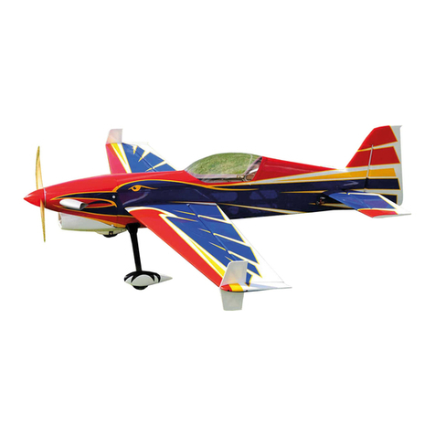
Extreme Flight YAK-54E User manual

Extreme Flight

Extreme Flight YAK-54E User manual

Extreme Flight 74" EDGE 540T ARF User manual

Extreme Flight

Extreme Flight 74" EDGE 540T ARF User manual

Popular Toy manuals by other brands

Airigami PAPIER AVION Boeing 737-200 quick start guide

Airigami

Airigami PAPIER AVION Boeing 737-200 quick start guide

Faller 190499/3 manual

Faller

Faller 190499/3 manual

marklin 72751 user manual

marklin

marklin 72751 user manual

Faller 130376 instructions

Faller

Faller 130376 instructions

Robotronics Buzz E. Smoke Alarm & Safety House operating manual

Robotronics

Robotronics Buzz E. Smoke Alarm & Safety House operating manual

Sparc Arrowhead SPJ1300 owner's manual

Sparc

Sparc Arrowhead SPJ1300 owner's manual

Mattel K7246 manual

Mattel

Mattel K7246 manual

Fisher-Price CADILLAC ESCALADE H0440 Owner's manual & assembly instructions

Fisher-Price

Fisher-Price CADILLAC ESCALADE H0440 Owner's manual & assembly instructions

LEGO 75058 instructions

LEGO

LEGO 75058 instructions

REVELL Sopwith Triplane Assembly manual

REVELL

REVELL Sopwith Triplane Assembly manual

Tabletop Scenics Fantasy Bowl Stadium Dice Tower Construction guide

Tabletop Scenics

Tabletop Scenics Fantasy Bowl Stadium Dice Tower Construction guide

MTHTrains Premier EF-3 Electric Engine Operator's manual

MTHTrains

MTHTrains Premier EF-3 Electric Engine Operator's manual

LEGO Star Wars 8084 Building instructions

LEGO

LEGO Star Wars 8084 Building instructions

Piper USAF MODEL L-21A AIRCRAFT Erection and maintenance instructions handbook

Piper

Piper USAF MODEL L-21A AIRCRAFT Erection and maintenance instructions handbook

Mega Construx Challenger Series quick start guide

Mega Construx

Mega Construx Challenger Series quick start guide

Mega Construx Wonder Builders Pokemon Snubbull manual

Mega Construx

Mega Construx Wonder Builders Pokemon Snubbull manual

Mattel Disney Magical Talking Castle instructions

Mattel

Mattel Disney Magical Talking Castle instructions

Fisher-Price Baby Playzone Swirlin' Saucer B9756 instructions

Fisher-Price

Fisher-Price Baby Playzone Swirlin' Saucer B9756 instructions

manuals.online logo
manuals.online logoBrands
  • About & Mission
  • Contact us
  • Privacy Policy
  • Terms and Conditions

Copyright 2025 Manuals.Online. All Rights Reserved.