manuals.online logo
Brands
  1. Home
  2. •
  3. Brands
  4. •
  5. Extron electronics
  6. •
  7. Media Converter
  8. •
  9. Extron electronics DSC 401 User manual

Extron electronics DSC 401 User manual

1
IMPORTANT:
IMPORTANT:
Go to www.extron.com for the complete
user guide, installation instructions, and
specifications before connecting the
product to the power source.
DSC 401 and DSC 401 A • Setup Guide
The Extron DSC 401 and DSC 401 A are high-performance, energy-efficient, HDMI-to-HDMI scalers capable of converting
between resolutions up to 4K @ 60 Hz with full 4:4:4 color sampling and 10-bit color. They support data rates up to 18 Gbps
and are HDMI 2.0 and HDCP 2.3 compliant. Both models feature an on-screen display (OSD), internal test patterns, and status
LEDs. The DSC 401 A model also features audio embedding and de-embedding, logo image keying and display, input presets,
and Ethernet control with power over Ethernet (PoE). The DSC 401 and DSC 401 A scalers are designed for locations such as
conference rooms or auditoriums where video conferencing, lecture capture, signal preview, and high-quality 4K scaling of HDMI
signals in a compact package is required.
Configuration and control options include front panel buttons and knobs, the OSD menu system, Simple Instruction Set™ (SIS™)
commands, Product Configuration Software (PCS), and Toolbelt software.
This setup guide provides step-by-step instructions for an experienced user to set up and configure the DSC 401 and 401 A. The
terms "DSC," "unit," and "scaler" are used interchangeably to refer to either model.
For full installation, configuration, menus, connector wiring, and operation details, see the DSC 401 and DSC 401 A User Guide,
available at www.extron.com.
Installation
ATTENTION:
• Installation and service must be performed by authorized personnel only.
• L’installation et l’entretien doivent être effectués par le personnel autorisé uniquement.
Rear Panel Features
POWER
0.9A MAX
12V
HDMI INPUTHDMI OUTPUT
DSC 401
AAABBBCCC
Figure 1. DSC 401 Rear Panel
POWER
0.9A MAX
12V
HDMI INPUT HDMI OUTPUT
DSC 401 A
LAN/PoE
AUDIO INPUT AUDIO OUTPUT
LR
A
A
AB
B
BC
C
CD
D
DE
E
EF
F
F
Figure 2. DSC 401 A Rear Panel
Setup Overview
1. Disconnect power — Turn off or disconnect all equipment power sources.
2. Mount the unit (optional) — Mount the DSC in a rack using a shelf mounting bracket kit or under furniture using a furniture
mounting bracket kit, available at www.extron.com (see the instructions provided with the kit).
3. Connect the HDMI video input and output — Connect an HDMI video source and
display to the HDMI input (see figures 1 and 2, B)and output (C)connectors. Secure
each HDMI device to the connector with a provided LockIt®bracket (see the DSC 401 and
DSC 401 A User Guide, available at www.extron.com, for instructions).
4. Connect analog audio input (DSC 401 A only, optional) — Connect an analog audio
source to the 3.5 mm TRS Audio Input connector (D, and see the image at right).
A
Power connector
B
HDMI input connector
C
HDMI output connector
D
Audio input connector
E
Audio output connector
F
Ethernet LAN connector with PoE
1
2
Sleeve ( )
Ring(R)
Tip(L)
3.5 mm Stereo Plug Connector
(balanced)
2
DSC 401 and 401 A • Setup Guide (Continued)
5. Connect an audio output device (DSC 401 A only, optional) — Connect an amplifier or audio system to the 5-pole
captive screw Audio Output connector (see figure2, Eon the previous page) for balanced or unbalanced stereo or mono
audio output.
Balanced Audio Output
Tip
Ring
Tip
Ring
Sleeves
Unbalanced Audio Output
Tip
No Ground Here
No Ground Here
Tip
Sleeves
LR
LR
Figure 3. Wiring the Audio Output Connector (DSC 401 A Only)
The output can contain de-embedded audio from the input source (two-channel LPCM only) or the analog input can pass
through. The analog output and the embedded digital audio outputs share volume adjustment controls (applies to analog
or LPCM-2Ch inputs only). If multi-channel formats (such as Dolby/DTS or multi-channel PCM audio) are used, the analog
output is muted and volume control has no effect on the embedded output.
6. Connect to a network (DSC 401 A only, optional) — For remote control, connect the unit to a network via the RJ-45
LAN/PoE connector (F), enabling configuration of the DSC via SIS commands, PCS or Toolbelt software, or the DSC 401
and 401 A web page. The LAN port supports PoE, which allows PoE network equipment to power the DSC 401 A.
NOTE: An external power supply is not required for a DSC 401 A using PoE.
7. If not using the provided pre-wired power supply, wire a 2-pole
captive screw connector (provided) to your power supply as
shown in the image at right.
Front Panel Overview
DSC 401
STATUS MENU HOLD FOR 1080p/4K
ENTER
R
SIGNAL IN
HDCP IN
HDCP OUT
CONFIG
B
B
B
A
A
A
C
C
CD
D
DE
E
EF
F
F
A Power and Reset LED D Signal Status LEDs
B Reset button E Menu and Enter buttons
C USB Config port F Navigation buttons
Figure 4. Front Panel — DSC 401
NOTE: Figure 4 shows the front panel of a DSC 401. The DSC 401 A front panel is identical except for the product name
(DSC 401 A) in the lower-right corner.
APower and Reset LED — This bicolor LED lights amber when the unit is powered on but no signal is present, blinks amber
every 3 seconds when the unit is in standby mode, and lights green when both power and an input video signal are present.
While the Reset button (see gure4, B) is pressed and held, this LED blinks after 6 seconds, then again after 9 seconds to
indicate the level of reset initiated if the button is released and momentarily pressed again at that point.
BReset button — Press this recessed button to access reset modes 1 (reset to factory firmware version), 4 (reset includes IP
defaults), and 5 (absolute system reset, including IP settings, user-defined settings, and user files).
CUSB Config port — Connect a host to this USB-C configuration port for device configuration with PCS or Toolbelt, control,
file transfer, or firmware updates.
DStatus LEDs — These green LEDs light to indicate the following:
• Signal In — An input signal is present.
• HDCP In — The input signal is HDCP-encrypted.
• HDCP Out — The output signal is HDCP-encrypted.
3
Captive Screw Connector
Tie Wrap
Heat
Shrink 1/8"
(3 mm)
7/8"
(22 mm)
3/16"
(5 mm) Max.
4
3
EMenu and Enter buttons — Use these buttons to access the on-screen display (OSD) and make menu selections.
FNavigation buttons (right , left , up , and down arrow buttons) — Use these four buttons to navigate the OSD
submenus, perform Auto-Image (press [DSC 401 A]), and reset the output rate (hold for 5 seconds, [DSC 401 A]).
Configuring the DSC 401 and 401 A
The DSC 401 and 401 A can be configured remotely through a host connected to the USB Config port or the LAN PoE port
(DSC 401 A only) using Extron PCS or Toolbelt configuration software (available at no charge at www.extron.com), SIS
commands (see Basic SIS Commands on page4), or the DSC 401 or 401 A internal web page (see the DSC 401 and 401 A
User Guide, available at www.extron.com). You can also configure the scaler locally using the OSD menu system.
OSD Menu System
The on-screen display (OSD) menu system consists of seven submenus and one read-only information screen (Device Info). To
access the menus, press the front panel Menu button. With the main menu displayed, use the navigation arrow buttons to step
through the submenus and submenu items. Press the Enter button to select highlighted items.
•Device Info •Input •Advanced
•Quick Setup •Output •Communication
•Picture Controls •Audio
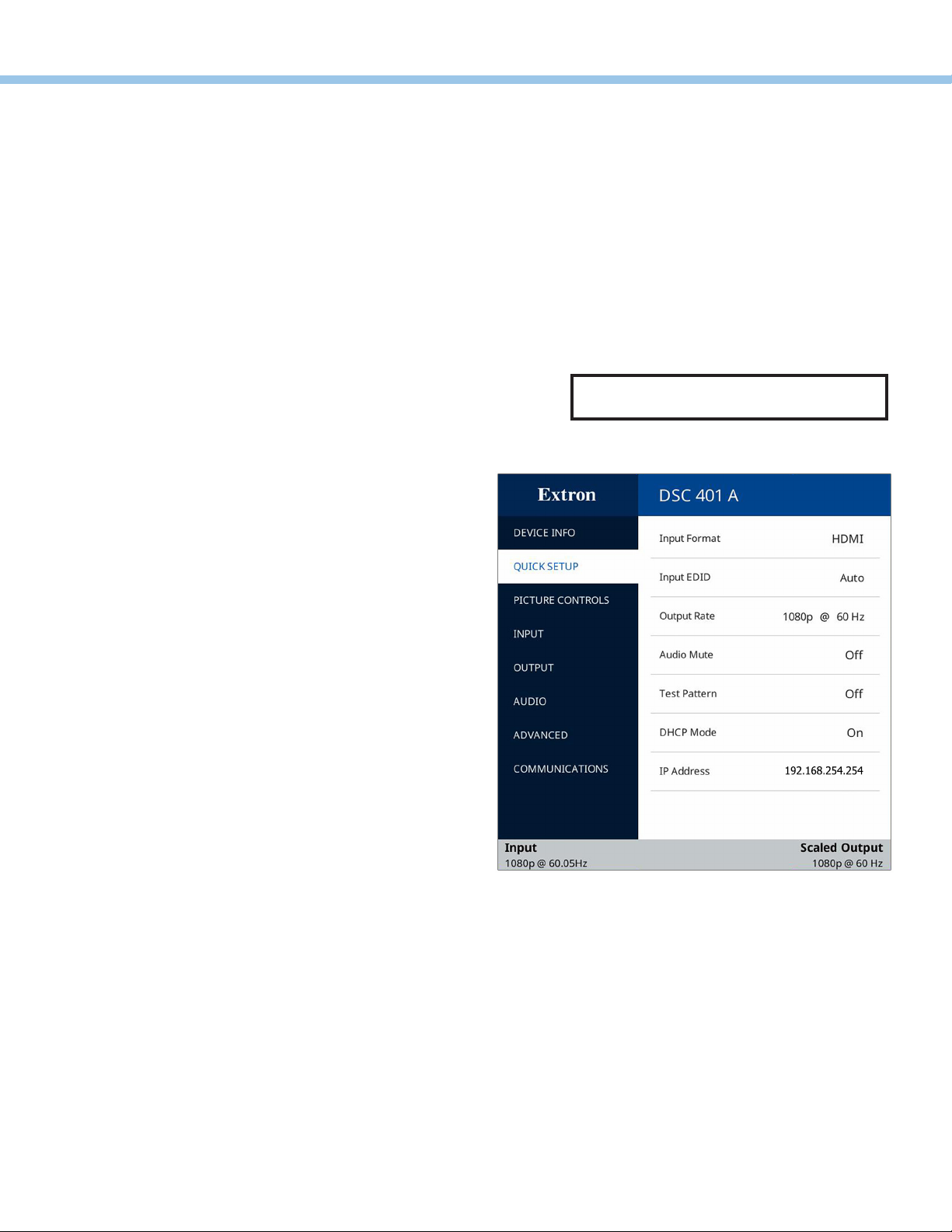
The Quick Setup submenu is displayed when the OSD opens. This submenu contains items that you are most likely to need
when configuring the DSC for the first time. To perform a basic setup and get started, select the following items as needed:
zInput Format — Displays the video format (HDMI [default]
or DVI) of the connected input.
zInput EDID — Select an input EDID (resolution and refresh
rate) to match the output rate or set a discrete EDID.
The default EDID selection is to match the scaler output
(1080p @60Hz in the example at right).
zOutput Rate — Select the scaler output resolution and
refresh rate from 80 available factory-installed rates.
You can also select one of three custom slots to add a
user-defined resolution. The default rate is 1080p @60Hz.
zAudio Mute — Press the navigation buttons to mute (On) or
unmute (Off) the audio. You can also select Analog to mute
analog audio or Digital to mute embedded digital audio.
zTest Pattern — Press the navigation buttons to select
an available test pattern to display or to turn a test
pattern off. The available test pattern selections are
Crop, Alternating Pixels, Color Bars, Grayscale (32
level), Crosshatch, and Audio Test (emits pink noise,
DSC 401 A only). The default setting is Off.
zDHCP Mode (DSC 401 A only) — Press the >and <
buttons to enable (On) or disable (Off [the default]) DHCP.
zIP Address (DSC 401 A only) — Press the >and <buttons to switch between octets. Press the and buttons to
change the value of a selected octet. The default address is 192.168.254.254.
Internal Web Pages
The DSC 401 and 401 A have an embedded web page, which is accessible via the USB Config port (both models) or the LAN PoE
port (DSC 401 A only). The web page contains fields that provide device information and some editing capabilities, as well as the
ability to update firmware.
Locking the Front Panel (Executive Mode)
To prevent unauthorized access or accidental changes to DSC settings, lock the front panel controls, making control available
only by SIS commands, PCS, Toolbelt, or the web page. (The default state is unlocked.)
zSIS commands — To lock the front panel, enter 1X. To unlock (disable executive mode), enter 0X.
zPCS or Toolbelt — See the DSC 401 and 401 A Help File or the Toolbelt help file, provided with the software.
Firmware Updates
Download rmware updates from the Extron website and upload them via the internal web pages, PCS, or Toolbelt.
NOTE: The OSD times out and closes after
1 minute if no buttons are pressed.
4
68-3539-50 Rev. A
02 21
For information on safety guidelines, regulatory compliances, EMI/EMF compatibility, accessibility, and related topics, see the
Extron Safety and Regulatory Compliance Guide on the Extron website.
© 2021 Extron — All rights reserved. www.extron.com
All trademarks mentioned are the property of their respective owners.
Worldwide Headquarters: Extron USA West, 1025 E. Ball Road, Anaheim, CA 92805, 800.633.9876
DSC 401 and 401 A • Setup Guide (Continued)
Output Rate Reset
If an image cannot be displayed due to an incompatible output rate, you can reset the output rate as follows: With the OSD off,
press and hold the button for approximately 5 seconds to toggle between 4K @ 60 Hz and 1080p @ 60 Hz.
Basic SIS Commands
The DSC 401 and 401 A can be configured with specific SIS commands via USB and, for DSC 401 A, a LAN connection. This
table lists a selection of basic commands. For a full list of SIS commands and variables see the DSC 401 and 401 A User Guide.
Command ASCII Command
(Host to Scaler)
Response
(Scaler to Host) Additional Description
Output Audio Mute (DSC 401 A Only)
Enable global audio mute 1Z Amt 1]Mute the audio on all outputs.
Disable global audio mute 0Z Amt 0]Unmute the audio on all outputs.
Discrete output mute or unmute X7!*X1)ZAmtX7!*X1)] Set audio mute of output X7! to X1).
View global audio mute status ZAmtX1)•X1)] View the audio mute status on all outputs.
View mute status of an output X7!*Z X1)] View mute status X1( of output X7!.
Volume (DSC 401 A Only) — Affects all analog and digital outputs simultaneously.
Set volume X5)V VolX5)] Set the output volume level to X5).
Increment volume +V VolX5)] Increase the output volume by 1 dB (to X5)).
Decrement volume -V VolX5)] Decrease the output volume by 1 dB (to X5)).
View volume level VX5)] View current volume setting X5).
Output Resolution and Rate
Set output scaler rate E1*X2! RATE}Rate 1*X2!] Select output resolution and refresh rate X2!.
View output rate E1RATE}X2!] View current output rate X2! for the DSC.
Resets
Soft reset EZXXX}Zpx]Reset all device settings to the factory defaults for a
single power cycle. Retains all user settings and les.
Absolute system reset EZQQQ}Zpq]Reset all device settings to factory defaults except
the rmware version. Includes setting DHCP to Off, IP
addresses to default, and the administrator password
to extron.
NOTE: The factory configured passwords for all accounts on this device have been set to the device serial number. Passwords are
case sensitive. In the event of an absolute system reset, the password is reset to extron.
Absolute system reset retaining
IP settings
EZY}Zpy]Reset all device settings to factory defaults except
IP addresses, DHCP setting, unit name, and port
mapping.
Front Panel Lock (Executive Mode)
Enable or disable front panel lock X2(X ExeX2(] Set the front panel lock mode to X2(.
View front panel lock mode XX2(]
KEY: X1) = On or Off status. 1= On or enabled, 0= Off or disabled
X2! = Output rate:* 34 = 720p @ 60 Hz, 45 = 1080p @ 60 Hz, 73 = 4096x2160 @ 30 Hz, 76 = 4096x2160 @ 60 Hz
*For a complete list of available resolutions and rates, see the DSC 401 and 401 A User Guide.
X2( = Front panel lock mode: 0= Disabled (front panel unlocked, default), 1= Enabled (complete front panel lock)
X5) = Volume: 0dB to 100 dB in 1.0 dB steps. (Default is -10 dB.)
X7! = Output audio number: 1= Analog audio output (DSC 401 A only), 2= Embedded HDMI audio output.

Other manuals for DSC 401

1

This manual suits for next models

1

Other Extron electronics Media Converter manuals

Extron electronics CLK 100 User manual

Extron electronics

Extron electronics CLK 100 User manual

Extron electronics SME 211 User manual

Extron electronics

Extron electronics SME 211 User manual

Extron electronics DVS 150 User manual

Extron electronics

Extron electronics DVS 150 User manual

Extron electronics mediaport 200 User manual

Extron electronics

Extron electronics mediaport 200 User manual

Extron electronics NAV E 501 User manual

Extron electronics

Extron electronics NAV E 501 User manual

Extron electronics VSC 500 User manual

Extron electronics

Extron electronics VSC 500 User manual

Extron electronics IN1606 User manual

Extron electronics

Extron electronics IN1606 User manual

Extron electronics PIP 422 User manual

Extron electronics

Extron electronics PIP 422 User manual

Extron electronics HAI 100 4K User manual

Extron electronics

Extron electronics HAI 100 4K User manual

Extron electronics CLK 100 User manual

Extron electronics

Extron electronics CLK 100 User manual

Extron electronics DVC RGB-HD A User manual

Extron electronics

Extron electronics DVC RGB-HD A User manual

Extron electronics SDI to Analog Video Converter SDI-AVR 100 User manual

Extron electronics

Extron electronics SDI to Analog Video Converter SDI-AVR 100 User manual

Extron electronics NAV SD 511 User manual

Extron electronics

Extron electronics NAV SD 511 User manual

Extron electronics DSC HD-HD User manual

Extron electronics

Extron electronics DSC HD-HD User manual

Extron electronics CVC 200 User manual

Extron electronics

Extron electronics CVC 200 User manual

Extron electronics II User manual

Extron electronics

Extron electronics II User manual

Extron electronics CD 400 User manual

Extron electronics

Extron electronics CD 400 User manual

Extron electronics Scan Converter VSC 500 User manual

Extron electronics

Extron electronics Scan Converter VSC 500 User manual

Extron electronics DVS 204 User manual

Extron electronics

Extron electronics DVS 204 User manual

Extron electronics mediaport 200 User manual

Extron electronics

Extron electronics mediaport 200 User manual

Extron electronics DSC 3G-3G A User manual

Extron electronics

Extron electronics DSC 3G-3G A User manual

Extron electronics BUC 202 User manual

Extron electronics

Extron electronics BUC 202 User manual

Extron electronics NAV 10E 401 D User manual

Extron electronics

Extron electronics NAV 10E 401 D User manual

Extron electronics Two InpuT VIdeo Scaler IN1502 User manual

Extron electronics

Extron electronics Two InpuT VIdeo Scaler IN1502 User manual

Popular Media Converter manuals by other brands

PCB Piezotronics 422E65/A Installation and operating manual

PCB Piezotronics

PCB Piezotronics 422E65/A Installation and operating manual

Calibre HQView-100S operating instructions

Calibre

Calibre HQView-100S operating instructions

Texas Instruments TLC5510 manual

Texas Instruments

Texas Instruments TLC5510 manual

ADF Web HD67909-A1 user manual

ADF Web

ADF Web HD67909-A1 user manual

Danfoss vlt fcd 302 operating instructions

Danfoss

Danfoss vlt fcd 302 operating instructions

SFORZATO DSC-010EX user manual

SFORZATO

SFORZATO DSC-010EX user manual

Antik GX-5000 Operation guide

Antik

Antik GX-5000 Operation guide

BHV Proteus-R Operation manual

BHV

BHV Proteus-R Operation manual

Interlogix FS MC250-1T/1S user manual

Interlogix

Interlogix FS MC250-1T/1S user manual

Cypress CP-1262HE Operation manual

Cypress

Cypress CP-1262HE Operation manual

AAxeon FCU-3002SX user guide

AAxeon

AAxeon FCU-3002SX user guide

Ikegami IEN-200HD Specifications

Ikegami

Ikegami IEN-200HD Specifications

MRC 0001802 quick start guide

MRC

MRC 0001802 quick start guide

Hirschmann OZDV 2471 P Technical description and operating instructions

Hirschmann

Hirschmann OZDV 2471 P Technical description and operating instructions

Vela Argus 2000-1500 Developer's guide

Vela

Vela Argus 2000-1500 Developer's guide

NEXENTRO Zigbee operating instructions

NEXENTRO

NEXENTRO Zigbee operating instructions

Miteq DNB1-3.8TR-INV manual

Miteq

Miteq DNB1-3.8TR-INV manual

SAFARI Montage G3011 Installation and setup guide

SAFARI Montage

SAFARI Montage G3011 Installation and setup guide

manuals.online logo
manuals.online logoBrands
  • About & Mission
  • Contact us
  • Privacy Policy
  • Terms and Conditions

Copyright 2025 Manuals.Online. All Rights Reserved.