1
Go to www.extron.com for the
product specifications.
MediaPort®300 • Setup Guide
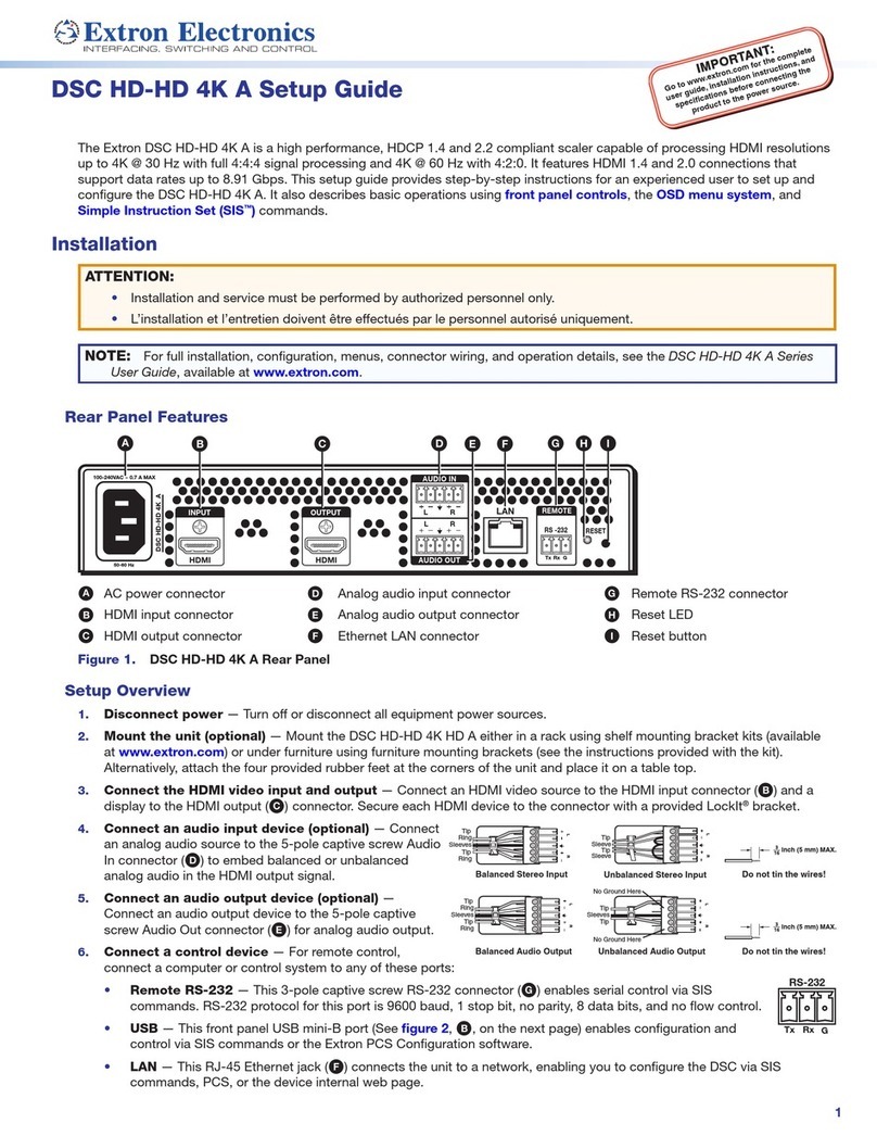
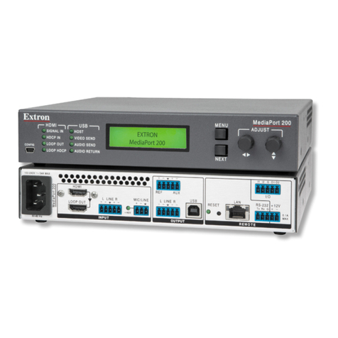
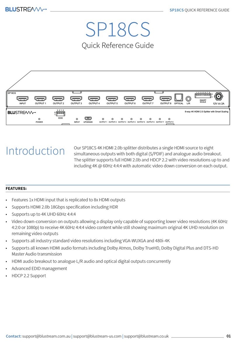
The MediaPort 300 is an HDMI and audio to USB scaling bridge that interfaces between pro AV
equipment and computer-based video conferencing and recording software. Incoming HDMI video is scaled and output via USB to a
host computer. Bi-directional audio is supported over the USB bus, including one stereo pair from the PC for application playback and
far-end communication audio, and one stereo pair to the PC for near-end local audio to be sent to the far end. Setup and control are
available via a front panel USB-C Conguration port and a rear panel Ethernet port. Simple Instruction Set (SIS™) commands and the
Windows®-based Extron Product Conguration Software (PCS) simplify initial conguration and real-time control. The 1-inch (2.54 cm)
high, half rack wide, 6 inches (15.24 cm) deep enclosure can be optionally mounted to a rack shelf, or under or through furniture.
Installation
Step 1 — Mounting
Turn off or disconnect all equipment power sources and mount the MediaPort 300 as required.
Step 2 — Rear Panel Connections
POWER
12V
1.3A MAX
MediaPort 300
USB-C
HOST
RESET
LAN/PoE+
HDMI
LOOP OUT
MIC/LINE LINE
1 2
+48V
INTPUT
LINE
OUTPUT
1 2
EEEGGGCCCFFFBBBDDDAAAIIIHHH
Figure 1. MediaPort 300 Rear Panel Features
AHDMI video input connector — Connect an HDMI video source to this HDMI input connector.
BHDMI video loop out connector — (Optional) Connect a local HDMI monitor (or a DVI monitor, with an appropriate adapter) or a
video conferencing hardware device to the HDMI Loop Out connector.
NOTE: See LockIt®Lacing Brackets on page 4 to secure the HDMI cables to Aand Band a USB type C cable to E.
CMic/Line input port — Connect one of the following to this connector (see Analog audio input connector on page 4).
• One analog balanced or unbalanced microphone input source or mono input source
• One analog balanced or unbalanced, line-level, mono input source
NOTE: The Phantom Power LED, D, lights when 48 V phantom power is supplied for the Mic/Line audio input.
EUSB Host connector — Connect a USB type C cable from this port to an appropriate USB port of a of a USB host device, such
as a PC or Mac for video and audio input and output. The front panel USB Host LED lights when this connection is made.
NOTE: Ensure that the USB host and USB-C cable support USB 3.x, otherwise the supported USB video resolutions are
severely limited.
FLine level audio output connector — Connect an amplifier or other device to the 6-pole captive screw Line output connector
for balanced or unbalanced, stereo or dual mono, analog output (see Line level audio output connector on page 4).
GLAN/PoE+ connector — Connect an Ethernet cable between this port and the network to configure and control the MediaPort
from a remote location using SIS commands, the Product Configuration Software (PCS), or the embedded web page. This port
can also receive Power over Ethernet (PoE+) to power the MediaPort 300 (see Power on page 2 for power options).
HReset button and LED — This button initiates three modes of reset (see the MediaPort 300 User Guide, at www.extron.com).
IPower connector — Plug the included external 12 VDC power supply into this 2-pole connector (see Power for power options).
NOTE:Alternatively, the MediaPort 300 can be powered via PoE+.
IMPORTANT:
Go to www.extron.com for the complete
user guide, installation instructions, and
specifications before connecting the
product to the power source.
