Cod. 732815_Rev. A
NA
C
NC
NA
C
NC
NA
C
NC
NA
C
NC
Output 4
Output 3
Output 2
Output 1
In 1
In 2
In 3
In 4
In 5
In 6
GND
In 7
PLITE (S)
ALI-SW-V
MISO
MOSI
SCK
SS-N
+12V
GND
D1-D
D0-C
BUZ
MISO
MOSI
SCK
SS-N
+12V
GND
D1-D
D0-C
BUZ
COM2-RS232
COM3-RS232
COM1-RS232
COM1-RS485
IN
OUT
+485
- 485
SCH
+485
- 485
SCH
TX
RX
RTS
CTS
GND
TX
RX
RTS
CTS
GND
TX
RX
RTS
GND
+12V
GND
+BATT
GND
IN-AC
IN-AC
GND
GND
L
N
GND
-24Vdc +24Vdc
NA
C
NC
NA
C
NC
NA
C
NC
NA
C
NC
Output 4
Output 3
Output 2
Output 1
In 1
In 2
In 3
In 4
In 5
In 6
GND
In 7
PLITE (S)
ALI-SW-V
MISO
MOSI
SCK
SS-N
+12V
GND
D1-D
D0-C
BUZ
MISO
MOSI
SCK
SS-N
+12V
GND
D1-D
D0-C
BUZ
COM2-RS232
COM3-RS232
COM1-RS232
COM1-RS485
IN
OUT
+485
- 485
SCH
+485
- 485
SCH
TX
RX
RTS
CTS
GND
TX
RX
RTS
CTS
GND
TX
RX
RTS
GND
+12V
GND
+BATT
GND
IN-AC
IN-AC
GND
GND
L
N
GND
NA
C
Output 4
In 1
In 2
In 3
In 4
In 5
In 6
GND
In 7
PLITE (S)
MISO
MOSI
SCK
SS-N
+12V
GND
D1-D
D0-C
BUZ
MISO
MOSI
SCK
SS-N
+12V
COM2-RS232
COM3-RS232
COM1-RS232
COM1-RS485
IN
OUT
+485
- 485
SCH
+485
- 485
SCH
TX
RX
RTS
CTS
GND
RX
RTS
CTS
TX
RX
RTS
GND
+12V
GND
+BATT
GND
IN-AC
IN-AC
GND
GND
B
n
n 5
N
7
2-R
232
T
T
N
ND
ND
LITE
S
BCDEFG
A
A
NA
C
NC
NA
C
NC
NA
C
NC
NA
C
NC
Output 4
Output 3
Output 2
Output 1
In 1
In 2
In 3
In 4
In 5
In 6
GND
In 7
PLITE (S)
ALI-SW-V
MISO
MOSI
SCK
SS-N
+12V
GND
D1-D
D0-C
BUZ
MISO
MOSI
SCK
SS-N
+12V
GND
D1-D
D0-C
BUZ
COM2-RS232
COM3-RS232
COM1-RS232
COM1-RS485
IN
OUT
+485
- 485
SCH
+485
- 485
SCH
TX
RX
RTS
CTS
GND
TX
RX
RTS
CTS
GND
TX
RX
RTS
GND
+12V
GND
+BATT
GND
IN-AC
IN-AC
GND
GND
ABCDEFG
NA
C
NC
NA
C
NC
NA
C
NC
NA
C
NC
Output 4
Output 3
Output 2
Output 1
In 1
In 2
In 3
In 4
In 5
In 6
GND
In 7
PLITE (S)
ALI-SW-V
MISO
MOSI
SCK
SS-N
+12V
GND
D1-D
D0-C
BUZ
MISO
MOSI
SCK
SS-N
+12V
GND
D1-D
D0-C
BUZ
COM1-RS232
COM1-RS485
IN
OUT
+485
- 485
SCH
+485
- 485
SCH
TX
RX
RTS
CTS
GND
TX
RX
RTS
CTS
GND
TX
RX
RTS
GND
+12V
GND
+BATT
GND
IN-AC
IN-AC
GND
GND
AB C D E F G
ENG
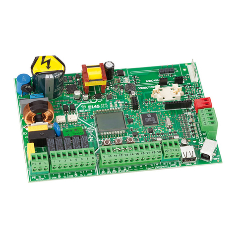
Fig.1 – CobraPlus part nr. 316030
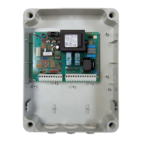
Fig.2 – ControllerPlus part nr. 103167
The board is supplied
with a toroidal
transformer.
1 - Cobra plus
2 - Controller plus
This product is equipped
with a 24VDC switching
power supply that lets you:
Supply power
to a detector for
managing the
magnetic loops
required by this
type of system;
Connect an
optional intercom
board;
Connect a TCP/
IP- RS232 network
converter
3 - FunCtions
Jumper CN1 lets you set the control board for the dedicated function.
The function is in any case also linked to the type of application the board is
used for. The following table contains the possible combinations.
Jumper
position in
CN1
Description Cobraplus +
AccessPlus
ControllerPlus +
Parkplus
ControllerPlus +
Accessplus
ATICKET DISPENSER - yes -
B
CASH-DESK (ON LANE OR DECENTRALISED)
- yes -
CSUBSCRIBERS (VEHICLES) - yes -
DSUBSCRIBERS (PEDESTRIANS) - yes -
ETICKET READER - yes -
FAUTOMATIC CASH-DESK - yes -
GACCESS CONTROL yes - yes
Fig.3 – Example of Function Jumper Setting in position “G”
In both versions, the board features:
2 reader inputs (connectors M1 and M2)
• It is possible to connect magnetic readers, proximity readers with
or without display and keyboard, long-range readers.
• The reader function can change depending on the type of fun-
ction assigned to the board. We recommend referring to the ma-
nual specific to the application being used.
2 inputs for communication with other devices:
• It is possible to connect the board to a system that uses RS485
protocol (connectors M11 and M12).
• It is possible to connect the board directly to a PC using RS232
protocol (connector M10). The same connector is able to create a
connection to a TCP/IP network by means of a TCP/IP – RS232
network converter.
2 additional COM ports, the use of which is specific to the applica-
tion being used.
4 - ConneCtions 5 - rs485 line ConneCtion
Fig.4 – Description of the connections
Fig.5 – RS485 Line connection
Power supply
230 Vac / 50-60 Hz
Power supply
230 Vac / 50-60 Hz
6 inputs (connector M4) whose function depends on the application being
used.
4 outputs (connectors M5 M6, M7 and M8) whose function depends on
the application being used.
Com 1
RS232 Data line
Power supply
Outputs Inputs
Com 2 Com 3
Reader AReader B
RS 485 Data line
PC Controller
RS 232 485
Converter CobraPlus /
ControllerPlus
+ RS 485 Polling in
- RS 485 Polling in
Sch RS 485 Polling in
+ RS 485 Polling out
- RS 485 Polling out
Sch RS 485 Polling out
The diagram shown in the figure below shows the connection modes when
the unit is used in an on-line system with Parkplus or Accessplus software.


