FAAC FSL700 User manual

Slide Gate Operator
FAAC International Inc.
Headquarter & East Coast Operations
3160 Murrell Rd
Rockledge, FL 32955
Tel. 800 221 8278
www.faacusa.com
FAAC International Inc.
West Coast Operations
357 South Acacia Avenue
Fullerton, CA 92831
FSL 700
UL325 - UL991


3
CONTENTS
Important Safety Information
Important Safety Instructions.......................................4
Important Installation Instructions................................4
General Safety Precautions.........................................5
UL325 Gate Operator Classication............................6
Installing the Warning Signs ........................................6
Restrictions and Warnings...........................................7
Precautions..................................................................7
Entrapment Protection.................................................8
Manual release............................................................9
Preinstallation Guidelines............................................9
Technical specication
Gate Operator Specications ....................................10
Gate Operator Installation
Gate Operator Location ........................................... 10
Concrete Pad Size & Location ................................. 11
Gate Operator Bolt Down ........................................ 12
Chain Connection - Front Mount ............................. 12
Chain Connection - Rear Mount .............................. 13
Limit Switch Setup ................................................... 14
Gate Operator Direction .......................................... 14
Electrical Installation
Power Switch Location ............................................ 15
AC Power Guidelines ............................................... 15
AC Power Connection ............................................. 15
Battery Power Connection ....................................... 16
Accessory Power ..................................................... 16
Master/Slave Connection ........................................ 17
Gate Operator Adjustments
Reverse Sensitivity Adjustment ............................... 18
Reverse Sensitivity Shutdown ................................. 18
Close Time Delay Adjustment .................................. 19
DIP Switch Settings ................................................. 19
Accessory Connections
Overview ....................................................................... 20
Photocell Sensor Connections ..................................... 21
Edge Sensor Connections ............................................ 22
Standard Reverse Connection ..................................... 23
Open, Close, Stop Connections ................................... 23
External Reset Connection ........................................... 23
Access Control Connection .......................................... 24
Fire Lock Connection .................................................... 24
Radio Receiver Connections ........................................ 25
MagLock & Solenoid Lock Connections ....................... 25
Warning Light Connections .......................................... 26
Solar Panel Connections .............................................. 26
Loop & Loop Detectors
Basic Loop Layout ........................................................ 27
Loop Installation Guidelines ......................................... 27
Plug-In Loop Detector Connections .............................. 28
External Loop Detector Connections ............................ 28
Troubleshooting Tips
Fault Light Count .......................................................... 29
Spare Parts
....................................................................................... 30
Limited warranty
....................................................................................... 32

4
1. Install the gate operator only when the following
conditions have been met:
• The operator is appropriate for the type and usage
class of the gate.
• All openings of a horizontal slide gate have been
guarded or screened from the bottom of the gate to
a minimum of 4 feet (1.25 m) above the ground to
prevent a 2.25 inch (55 mm) diameter sphere from
passing through openings anywhere in the gate or
through that portion of the adjacent fence that the gate
covers when in the open position.
• All exposed pinch points are eliminated or guarded.
• Guarding is supplied for exposed rollers.
2. The operator is intended for installation on gates used
by vehicles only. Pedestrians must be provided with a
separate access opening.
3. To reduce the risk of entrapment when opening and
closing, the gate must be installed in a location that
allows adequate clearance between the gate and
adjacent structures. Swinging gates shall not open
outward into public access areas.
4. Before installing the gate operator, ensure that the gate
has been properly installed and that it swings freely in
both directions. Do not over-tighten the operator clutch or
pressure relief valve to compensate for a damaged gate.
5. User controls must be installed at least 6 feet (1.83
m) away from any moving part of the gate and located
where the user is prevented from reaching over, under,
around or through the gate to operate the controls.
Controls located outdoors or those that are easily acces-
sible shall have security features to prevent unauthorized
use.
6. The Stop and/or Reset buttons must be located within
line-of-sight of the gate. Activation of the reset control
shall not cause the operator to start.
7. All warning signs and placards must be installed
and easily seen within visible proximity of the gate. A
minimum of one warning sign shall be installed on each
side of the gate.
Important Installation Instructions
WARNING - TO REDUCE THE RISK OF SEVERE
INJURY OR DEATH:
• READ AND FOLLOW ALL INSTRUCTIONS.
• Never let children operate or play with the gate
controls. Keep remote controls away from children.
• Always keep people and objects away from the
gate. NO ONE SHOULD CROSS THE PATH OF A
MOVING GATE.
• Test the gate operator monthly. The gate MUST
reverse on contact with a rigid object or when an
object activates a non-contact sensor. If necessary,
adjust the force or the limit of travel and then retest
the gate operator. Failure to properly adjust and retest
the gate operator can increase the risk of injury or
death.
• Use the manual release mechanism only when the
gate is not moving.
• KEEP GATE PROPERLY MAINTAINED. Have
a qualied service person make repairs to gate
hardware.
• The entrance is for vehicles only. Pedestrians must
use a separate entrance.
• SAVE THESE INSTRUCTIONS.
Important Safety Instructions
IMPORTANT SAFETY INFORMATION

5
Gate Construction
Vehicular gates should be constructed and installed
in accordance with ASTM F2200: Standard Specica-
tion for Automated Vehicular Gate Construction.
For more information, contact ASTM at: www.astm.org
Installation
• If you have any questions or concerns regarding the
safety of the gate operating system, do not install the
operator and consult the manufacturer.
• The condition of the gate structure itself directly
aects the reliability and safety of the gate operator.
• Only qualied personnel should install this equipment.
Failure to meet this requirement could cause severe
injury and/or death, for which the manufacturer
cannot be held responsible.
• The installer must provide a main power switch that
meets all applicable safety regulations.
• It is extremely unsafe to compensate for a damaged
gate by increasing hydraulic pressure.
• Install devices such as reversing edges and photo
beams to provide better protection for personal
property and pedestrians. Install reversing devices
that are appropriate to the gate design and
application.
• Before applying electrical power, ensure that voltage
requirements of the equipment correspond to the
supply voltage. Refer to the label on your gate
operator system.
Usage
• Use this equipment only in the capacity for which it
was designed. Any use other than that stated should
be considered improper and therefore dangerous.
• The manufacturer cannot be held responsible
for damage caused by improper, erroneous or
unreasonable use.
• If a gate system component malfunctions, disconnect
the main power before attempting to repair it.
• Do not impede the movement of the gate, you may
injure yourself or damage the gate system as a result.
• This equipment may reach high thermal temperatures
during normal operation, therefore use caution when
touching the external housing of the gate operator.
• Use the manual release mechanism according to the
procedures presented in this manual.
• Before performing any cleaning or maintenance
operations, disconnect power to the equipment.
• All cleaning, maintenance or repair work must
performed by qualied personnel.
General Safety Precautions
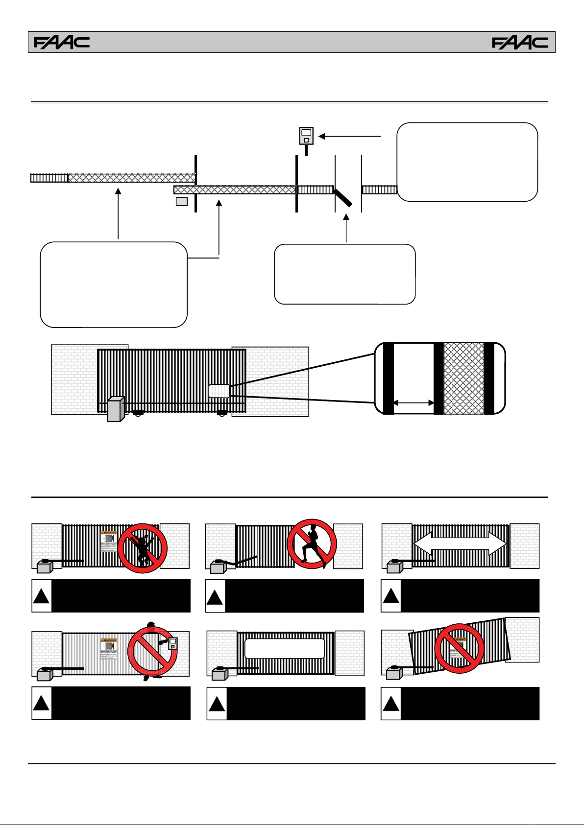
8. For gate operators that utilize a non-contact sensor
(photo beam or the like):
• See instructions on the placement of non-contact
sensors for each type of application.
• Exercise care to reduce the risk of nuisance tripping,
such as when a vehicle trips the sensor while the
gate is still moving.
• Locate one or more non-contact sensors where the
risk of entrapment or obstruction exists, such as at
the reachable perimeter of a moving gate or barrier.
• Use only FAAC “Photobeam” photoelectric eyes to
comply with UL325.
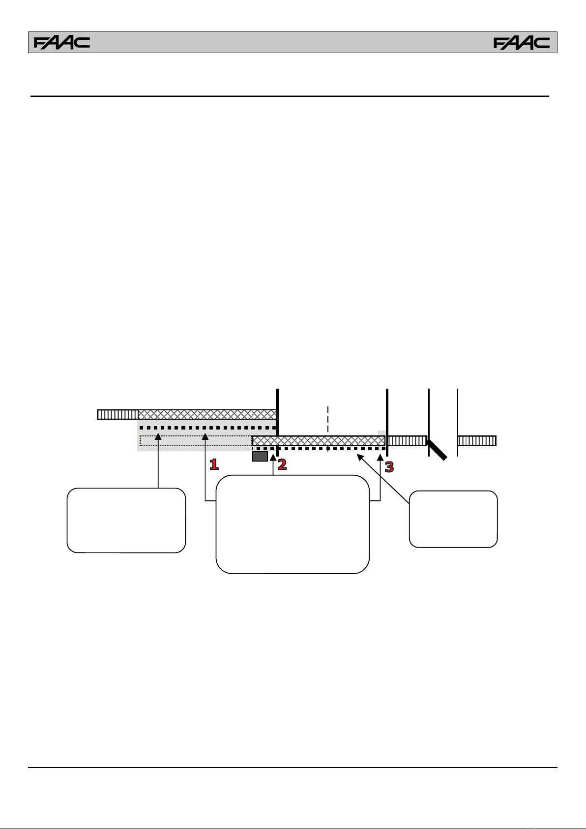
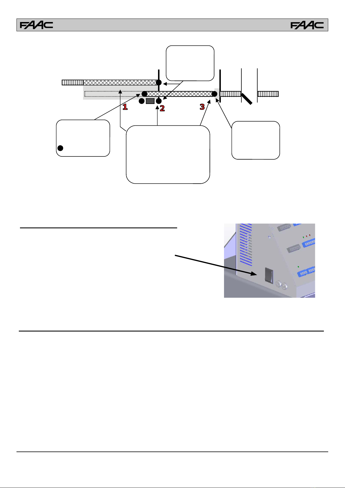
9. For gate operators that utilize a contact sensor (edge
sensor or similar):
• Locate one or more contact sensors where the risk
of entrapment or obstruction exists, such as at the
leading edge, trailing edge, and post mounted both
inside and outside of a vehicular horizontal slide
gate
• Locate one or more contact sensors at the bottom
edge of a vehicular vertical lift gate.
• Locate one or more contact sensors at the bottom
edge of a vertical barrier (arm).
• Locate one or more contact sensors at the pinch
point of a vehicular vertical pivot gate.
• Locate hard-wired contact sensors and wiring so
that communication between sensor and gate
operator is not subjected to mechanical damage.
• Locate wireless contact sensors, such as those
that transmit radio frequency (RF) signals, where
the transmission of signals are not obstructed or
impeded by building structures, natural landscaping
or similar hindrances. Wireless contact sensors shall
function under their intended end-use conditions.
• Use only FAAC XS 55 edge sensors with with CN 60
E controller.
Important Installation Instructions (continued)

6
RESIDENTIAL VEHICULAR GATE OPERATOR CLASS I
A vehicular gate operator system intended for use in a single family dwelling, garage or associated parking area.
UL325 Gate Operator Classications
COMMERCIAL / GENERAL ACCESS VEHICULAR GATE OPERATOR CLASS II
A vehicular gate operator system intended for use in commercial locations or buildings such as multi-family housing
units (ve or more single family units), hotels, parking garages, retail stores or other buildings that service the general
public.
INDUSTRIAL / LIMITED ACCESS VEHICULAR GATE OPERATOR CLASS III
A vehicular gate operator system intended for use in industrial locations or buildings such as factories, loading docks
or other locations not intended to service the general public.
RESTRICTED ACCESS VEHICULAR GATE OPERATOR CLASS IV
A vehicular gate operator system intended for use in guarded industrial locations or buildings such as airport security
areas or other restricted access locations that do not service the general public, and in which unauthorized access is
prevented via supervision by security personnel.
This FAAC gate operator is supplied with two warning
signs to alert people that a possible hazard exists and that
appropriate actions should be taken to avoid the hazard or
to reduce exposure to it.
Permanently install one warning sign on each side of the
gate so they are fully visible to trac and pedestrians.
Use appropriate hardware such as metal screws (not sup-
plied) to permanently install each warning sign.
Installing the Warning Signs

7
Space or screen to prevent a 2 1/4 inch
sphere from passing through.
Vehicular Gate Only
Pedes-
trian
Fence
FenceFence
All openings of a slide gate are guarded
or screened from the bottom of the gate
to a minimum or 4 feet (1.2m) above the
ground to prevent a 2 1/4 inch
(57.15mm) diameter sphere from
passing through the openings anywhere
in the gate, and the portion of the
adjacent fence that the gate covers in
the open position.
The operator is intended for installation
only on slide gates used for vehicular
traffic. Pedestrians must be provided
with a separate access opening.
NO ONE SHOULD CROSS THE PATH
OF A MOVING GATE!
Gate operator controls must be placed
far enough from the gate to prevent the
user from coming in contact with the
gate while operating the controls. All
activating devices must be installed in
a clear line-of-sight with the gate and
its travel. Be sure to mount all devices
clearly out of reach of through gate.
Restrictions and Warnings
DO NOT allow children to play
near, on or with the gate, gate
operator, or any of its controls.
1000 lb. Maximum
40 Feet Maximum
DO NOT mount the gate operator
to a gate longer than 40 feet.
Maximum gate length = 40 feet.
DO NOT allow pedestrian use of the
vehicular gate. No one should cross
the path of a moving gate!
!
DO NOT mount the gate operator
on uphill or downhill applications.
Do not allow gate to free swing.
DO NOT mount the gate operator
to a gate heavier than 1000 lbs.
Maximum gate weight = 1000 lbs.
DO NOT mount operating devices
accessible through the gate or in
between the gate and wall.
!!
!!!
Precautions

8
Inherent Entrapment Protection:
This vehicular gate operator is equipped with an inherent (Type A) entrapment sensing device. The system will sense an obstruction
in both the open and close cycles, and will reverse the direction of the gate travel upon encountering an obstruction. If the system
detects a second obstruction before reaching the full open or close limit after the initial reversal, a warning alarm will activate and
the operator will require a reset before resuming normal operation. This is called a “Hard Shutdown”. Please read and follow the
“Shutdown Conditions” section of this manual for more directions.
External Entrapment Protection:
Non-contact and/or contact sensors must be installed to provide external entrapment prevention in accordance with UL325 section
3.1. Use only UL325 compliant devices and low voltage (24V) devices. Carefully follow the installation manual for the UL325 device
used for installation, usage, and maintenance.
Non-Contact Sensors (Photo Beams):
Non-contact sensors generally are photoelectric cells or like devices. For gate operators utilizing non-contact sensors:
Refer to the diagram below for placement of non-contact sensors.
Use care to reduce the risk of nuisance tripping, such as when a vehicle trips the sensor while the gate is still moving.
One or more non-contact sensors shall be located where a risk of entrapment or obstruction exists, such as the perimeter reachable
by a moving gate or barrier. Use caution when installing non-contact sensors since some devices only cover a select area. For
example, a photo beam will not cover the full height of a gate/fence area. Refer to the diagram below.
Vehicular Gate Only
Pedestrian
Access
Fence
FenceFence
Protect against all entrapments
areas that exist:
1. Between the gate and the adjacent
fence when the gate is in the open
cycle
2. The gate operator and the slide gate
when the gate is in the open and
close cycles
3. At the front end of the gate when the
gate is in the close cycle.
Open beams help protect
areas between the gate and
the adjacent fence. CAUTION:
This beam should be used in
conjunction with a contact
sensor.
Close beams help
prevent the gate from
hitting obstructions
during the close cycle.
Contact Sensors (Edge Sensors):
Contact sensors generally are sensing edges or like devices. For gate operators utilizing contact sensors:
Refer to the diagram below for placement of contact sensors.
One or more contact sensors shall be located where the risk of entrapment or obstruction exists, such the leading edge, trailing edge,
and posts mounted inside and outside of the vehicular slide gate and motor.
Hardwired contact sensors shall be located and its wiring arranged so the communication between the sensor and the gate operator
is not subject to any mechanical damage.
Wireless contact sensors such as ones that transmit radio frequency (RF) signals to the gate operator for entrapment prevention
functions shall be located where the transmission of the signals are not obstructed or impeded by building structures, landscaping
or similar obstructions. All wireless contact sensors shall function under the intended end-use conditions.
Entrapment Protection

9
Pedestrian
Access
Fence
FenceFence
Protect against all entrapments
areas that exist:
1. Between the gate and the adjacent
fence when the gate is in the open
cycle
2. The gate operator and the slide gate
when the gate is in the open and
close cycles
3. At the front end of the gate when the
gate is in the close cycle.
Trailing edge sensor
helps protect areas be-
tween the gate and the
adjacent fence.
= Edge Sensor
Leading edge sensor
helps protect areas in
front of the gate.
Post edge sensors
help protect areas
inside and outside of
the gate and around
the operator
Preinstallation Guidelines
Before starting any installation, consider the following guidelines:
• Install the gate system and gate in accordance with ASTM F220-02 Standard Specication for Automated Vehicular Gate Construction
• Install the gate system and gate in accordance with UL325 standards.
• Provide spacing between the gate and any structure such as a building, wall or fence to reduce the risk of entrapment in this area.
• Install over-travel stops at both ends of the gate rail or track to help prevent the gate from derailing
• Be sure the gate is properly installed and moves freely. Repair or replace worn or damaged gate hardware before installing the
gate operator.
• Add safety devices such as warning signs, photo eyes, and reverse edges to help prevent injuries or death.
• Reduce all pinch points and protect all entrapment areas.
• If pedestrian trac will be present, provide a separate pedestrian walk gate clear from the path of the automatic gate.
• Loops and loop detectors are required to help prevent the gate from closing on vehicles. Loops do not protect pedestrian trac.
• Select the proper gate operator for the installation. Consider the usage, capacity, gate size, gate weight, and needed features an
safety accessories.
Manual Release
To manually release the gate operator remove the cover and locate
the Power ON-OFF switch.
Turning the power OFF allows the gate to be moved manually.
Turning the power back ON will resume normal operation.

10
TECHNICAL SPECIFICATION
FSL 700 Slide Gate Operator
The FAAC Model FSL 700 is an electro-mechanical vehicular slide gate operator. The direct drive 24V motor allows for smooth start
and stop operation, with easy to set limit switches. It has a built in battery backup system and 2 accessory power plugs. The adjust-
able chain idlers allow front, rear and post mount operation.
Input voltage 120 VAC (+5% -5%)
Power 500 W
Current 5 A
Motor voltage 24 VDC
Motor power 0.67 hp (0.5 KW)
Leaf max weight 1000 lb (454 Kg)
Leaf max length 40 ft (12 m)
AC accessory outlets 2 GFCI protected
AC accessory current 4 A
Gate speed 12 in/sec
Gearbox 15:1 fail safe
Use frequency 75 cycles/h
Operating temperature -4°F ÷ 131°F (-20°C ÷ +55°C)
Operator weight 125 lb (57 Kg)
Chain height - front mount 11 in (278 mm) from base
Chain type # 41
Gate Operator Location
Select a location for the gate operator to be installed prior to pouring the concrete pad. There are two ways to mount a slide gate
operator: the traditional front mount, or the rear mount method. Both methods have their advantages and will reliably open the gate.
The front mount method places the operator up front near the
ow of trac and uses a single chain across the length of the
gate.
Avantages:
• Less chain is required for the application
• Does not require the use of an additional idler sprocket
• Less room is needed for the application
Disadvantages:
• The operator is up front near the ow of trac allowing for
a vehicle to damage the operator more easily.
• The chain runs across the length of the gate allowing visi-
tors to see and possible tamper with it.
The rear mount method places the operator at the back of the
gate and uses a double chain with an additional idler sprocket.
Advantages:
• The chain is attached to the rear of the gate and is not vis-
ible when the gate is closed.
• The operator is in the back away from the ow of trac for
added safety.
Disadvantages:
• Twice as much chain is required for this type of application
• The application requires the use of an additional idler
sprocket
Front Mount Method: Rear Mount Method
15 in
18 in
22 in
GATE OPERATOR INSTALLATION
Gate Operator Specications

11
Concrete Pad Size & Location:
The FSL700 vehicular gate operator is designed to be mounted on a concrete pad. Select a location for the gate operator to be
installed. For pad location and size:
1. Determine the location for the operator to be installed. (Front Mount v. Rear Mount)
2. Follow all local building codes to determine the required depth of the concrete pad. The
average concrete pad should be 24” wide x 24” long x 28” deep
3. Extend the pad 4” above ground and 24” below ground.
4. When the exact location of the operator can be predetermined, all conduits may be
located in the concrete pad terminating directly under the operator. Extend each conduit
a minimum of 1” above the level of the concrete pad. See the Conduit Location diagram
below. It is suggested to install a minimum of four (4) conduits: (1) High Voltage Conduit,
(1) Low Voltage Conduit , (1) Loop Lead Wire Conduit, (1) Accessory Conduit.
5. When the exact location of the operator can not be predetermined, bring all conduits up
to one side and terminate in a Bell Box. Make connections to the operator using water-
tight ex conduit.
6. Form the concrete pad as shown and pour concrete. Allow the concrete to cure for 48 hours before removing the forms and
mounting the operator.
7. Do not place mounting bolts in the concrete while pouring. Bolts may drift in wet concrete making the operator location inaccu-
rate.
NOTE: The path of the gate and gate track must be installed on concrete. The average gate track concrete should be a minimum
of 10” wide x 12” deep the entire length of the gate track and travel. Failure to place the gate track on concrete can result in track
movement and cause gate failure or derailment.
Available
Conduit
Area
14” Wide x 12.5” Deep
GATE (2” x 2” Frame)
1.25”
Distance From
Gate To C ov er
Gate
Bracket
3.5”
Distance From
Gate to Op erator
Frame ( 3.5”)
12.5”
2.75”
Distance From
Gate T o Ch ain
14”
17”
24”
4”
24”
24”
WARNING: Install over-travel stops at both ends of the gate rail or track for all types of installations to help prevent the gate
from derailing.

12
Gate Operator Bolt Down
To align the operator to the gate and bolt it down:
1. Remove the gate operator cover and place the operator on the concrete pad. Position the operator with a distance of 3.5” from
the gate to the back frame of the operator. IMPORTANT: Make sure the gate and operator are parallel and level with each
other.
2. Mark the mounting holes and remove the operator. Drill the mounting holes to the required depth and diameter for the sleeve
anchors being used. It is recommended to use 3/8” x 4” sleeve anchors. The use of sleeve anchors allows greater exibility
and makes the installation and alignment much easier.
3. Clean the mounting holes and install the sleeves. Position the operator over the anchors. Recheck to make sure the gate and
operator are parallel and level with each other. Tighten the anchor bolts to securely hold the operator.
GATE
GATE
OPERATOR
3.5
CORRECT
! WRONG !
GATE
Chain Connection - Front Mount
Once the gate operator is securely bolted down, the chain may be attached. To attach the chain for a front mounted system:
1. Make sure the chain will be in a straight line and same height as the lower idler sprockets.
2. Weld the chain brackets to the end of each side of the gate and level with the lower idler sprockets. (Approximately 11”)
3. Route the chain through the operator, over the rst lower chain idler, under the chain sprocket, and over the second lower idler.
4. Connect the chain bolts to each end of the chain using the supplied master links. Connect the chain bolts to the chain brack-
ets. Adjustments to the chain length should be made now.
5. Tighten the chain using the chain bolts so the chain does not sag more than one (1) inch per 10 feet of travel. Do not over
tighten!
GATE
GATE
OPERATOR
CORRECT
GATE
GATE
OPERATOR
! WRONG !
CORRECT
Approx.
11”
! WRONG !

13
Chain Connection - Rear Mount
Rear mount operators require the use of an endless idler assembly and twice as much chain. Approximately 1 foot of added open-
ing space is needed. Once the gate operator is securely bolted down, the chain may be installed for a rear mount system.
1. Adjust the chain idler sprocket inside the gate operator for a rear mount application. Remove the lower idler on the unused
side and move it to the upper idler hole on the chain side of the operator. Both chain idlers should be above/below each other.
2. Increase the cover chain slot on the chain side of the operator. (Side toward the gate opening)
3. Close the gate and mount an endless idler assembly near the back of the gate. The chain must extend beyond the back of the
gate.IMPORTANT: Only use an endless idler assembly with a safety guard to prevent pinch and entrapment points.
4. Adjust the height of the endless idler sprocket so the chain from the lower chain idler is level with the bottom of the endless
idler. (Approximately 11”) Make sure the chain will be in a straight line and same height as the lower idler sprocket.
5. Weld the bottom chain bracket to the end of the gate and level with the top of the endless idler sprocket. (Height depends
upon the size of the endless idler sprocket)
6. Weld the top chain brackets to the end of the gate and level with the top of the upper idler sprocket. (Approximately 15”)
7. Route the chain through the operator, over the upper chain idler, around and under the chain sprocket, and over the lower idler.
8. Route the lower chain under and around the endless idler assembly.
9. Connect the chain bolts to each end of the chain using the supplied master links. Connect the chain bolts to the chain brack-
ets. Adjustments to the chain length should be made now.
10. Tighten the chain using the chain bolts so the chain does not sag more than one (1) inch per 10 feet of travel. Do not over
tighten!
WARNING: DO NOT INSTALL this product unless all
safety standards are followed and all entrapment and
pinch points have been eliminated.

14
Limit Switch Setup
The gate operator uses a limit switch assembly to adjust the dis-
tance of travel. These adjustments should be made before power
is supplied to the operator. To adjust the distance of travel using
the limits:
1. Turn power OFF! Use the power switch on the side to assure
AC and Battery power are both OFF.
2. Manually move the gate fully to the right. Push the limit guide
plate down and roll the top limit nut until it activates the top limit
switch. The switch will click when activated.
3. Manually move the gate to the left. Push the limit guide plate
down and roll the bottom limit nut until it activates the bottom
limit switch. The switch will click when activated.
4. Release the limit guide plate and make sure it is engaged in
the slots of each limit nut.
5. Readjust the limit nuts as necessary to ne tune the full-open
and full-closed positions.
RIGHT
LEFT
Gate Operator Direction
The gate operator uses a DIP switch setting to determine the open and close direction. To set the Open/Close direction:
1. Turn power OFF! Use the power switch on the side to assure AC and Battery power are both OFF.
2. Standing inside the gate looking at the gate operator, determine if the gate opens to the LEFT or RIGHT.
3. If the gate opens to the LEFT, move DIP SWITCH 6 to the Left.
4. If the gate opens to the RIGHT, move DIP SWITCH 6 to the Right.
Opens LEFT
Opens RIGHT
Monitor Photo / Edge
Anti-Tailgate
Master / Slave
Close Timer
Power Fail Open / Cycle
Open Left / Right
Quick Close
Stop (NC / NO)
Low Battery Cycle / Open
Mag / Solenoid Delay
Monitor Close / Op-Cl
Soft Start / Hard Start
Off On
DIP SWITCH 6
Monitor Photo / Edge
Anti-Tailgate
Master / Slave
Close Timer
Power Fail Open / Cycle
Open Left / Right
Quick Close
Stop (NC / NO)
Low Battery Cycle / Open
Mag / Solenoid Delay
Monitor Close / Op-Cl
Soft Start / Hard Start
Off On
DIP SWITCH 6

15
Power Switch Location
The gate operator uses a built-in power switch to control power to the operator and controller. This switch should be turned OFF
during installation and service. Failure to use this switch can result in unexpected gate movement. Please note:
1. The switch is located on the LEFT side of the control box.
2. DOWN position = OFF. UP position = ON.
3. This switch must be used to turn OFF AC and battery power. Only disconnecting AC power still allows battery power to the
operator, controller, and accessories.
4. Turn OFF until the installation is complete.
AC Power Guidelines
Under normal conditions, the gate operator will use a single phase AC power line to operate the gate, charge the batteries, and
power gate accessories. Use the following guidelines when installing the AC power:
1. Check the local wiring codes in all cases and follow all local building codes. Wiring and hookup should be performed by a quali-
ed electrician/installer only.
2. AC power should be supplied from a circuit breaker panel and must have its own dedicated circuit breaker. This supply must
include a green ground conductor.
3. Only use U.L. approved 14 AWG or larger 600 Volt Insulated Wire. Use the following chart to determine the AC wire size. This
information is for suggested use only - Check your local codes before installation.
4. Properly ground the gate operator to minimize or prevent damage from power surges and/or lightning. Use a grounding rod if
necessary. A surge suppresser is recommended for additional protection.
Wire Size (AWG) Distance (feet)
14 250
12 400
10 650
8 1000
AC Power Connection
To connect AC power to the gate operator:
1. Turn the circuit breaker for the AC gate operator power OFF before connecting the AC input wires.
2. Turn the Power Switch OFF located on the left side of the controller before connecting the AC input wires.
3. Connect the AC input wires to the AC terminal located on the bottom/center of the control box. See diagram below.
4. Batteries must be installed after the AC power is on. See Battery Power Connection.
L N
GREEN = Earth Gro und
WHITE = Neutral
BLACK = 120 VAC
ELECTRICAL INSTALLATION

16
Accessory Power
Two plug-in power plugs are located on the back of the controller. These plugs are for low voltage accessories and are separately
fused. Low voltage, low current draw transformers may be plugged into these outlets for accessory power. DO NOT USE THESE
POWER OUTLETS FOR INSTALLATION OR SERVICE TOOLS. Each plug supplies 110 VAC when AC power is active to the gate
operator. If AC is not available, the power plugs will not supply power. Accessories requiring power during battery backup modes
should use the 24 VDC located on the controller terminals.
Additional accessory power may be found on the controller terminals. The controller terminals supply 24 VDC for accessories. This
power is available during AC and battery power modes. When AC power is active, accessories will be supplied 24 VDC without a
power draw on the batteries. When the battery backup mode is active, accessories will be supplied 24 VDC from the batteries. If
the battery power mode is used frequently, consider the current draw of the accessories. The lower the current draw, the longer the
battery power supply will last. Additional 24 VDC for accessories may be found on the Radio Terminal, Edge/Photo Terminal, and
External Loop Terminal. A connection between 24V DC+ and GND will supply power.
Battery Power Connection
If AC power is connected, the system does not need the batteries to function. However, the batteries must be connected for the
Power Fail Battery Backup features to operate. When AC power is active, the batteries will charge until fully charged. Once the
batteries have fully charged, the system will stop charging. Charging is automatic when AC power is available. The system should
be prewired with the batteries. If not, to connect batteries to the system as showed below.
GND
GND
Open N.O.
Reverse N.O.
Shadow N.O.
24V DC
+
Std Reverse
Photo Open
Photo Close
GND
GND
Edge Open
Edge Close
24V DC
+
Radio Pwr
-24V DC
GND
N.O.
Radio Pwr
+24V DC
• Batteries should be tested regularly for proper battery backup operation.
• Batteries should be replaced each year or as needed.
12VDC, 8 amp
Battery
12VDC, 8 amp
Battery
+
+
-
-
RED
BLACK
Solar -
Solar +
Battery -
Battery +

17
Master/Slave Connection
The operator can be used in a Master-Slave conguration to control the two leafs of a bi-parting gate. That can be done with a
wired or wireless connection. The wired connection should be the default choice if there is a way to bring a cable across the gate
opening. If that’s impractical you can use the wireless connection accessory WMS100 to establish the communication between
Master and Slave. In the latter case you need to make sure there is no metal blocking the line of sight between the two operators,
for example a metal gate with no openings.
To connect two operators together:
1. Determine which operator is the Master and which operator is the slave. All external devices such as loop detectors and
safety devices must be wired directly to the Master unit. If one gate travels farther than the other the gate that travels
farther must be the Master
2. Turn Slave Operator DIP Switch 3 to ON = SLAVE
3. Turn Master Operator DIP Switch 3 to OFF = MASTER
4. WIRED CONNECTION: in a separate conduit, run a 6-conductor cable (twisted pairs) between the Master operator and the
Slave operator. Make the connections on the Master/Slave Terminal Block following the schematic below. (Recommended
Wire: Outdoor Rated CAT 5 Cable. If shielded make sure the shield is connected on one side only)
[RX –] to [TX –] ORANGE-WHITE
[RX+] to [TX+] ORANGE
[TX–] to [RX–] GREEN-WHITE
[TX+] to [RX+] GREEN
[GND[ to [GND] BROWN
Power
Monitor Photo / Edge
Anti-Tailgate
Master / Slave
Close Timer
Power Fail Open / Cycle
Open Left / Right
Quick Close
Stop (NC / NO)
Low Battery Cycle / Open
Mag / Solenoid Delay
Tamper Detect
Soft Start / Hard Start
Off On
Master / Slave
Interconnect
Power
Monitor Photo / Edge
Anti-Tailgate
Master / Slave
Close Timer
Power Fail Open / Cycle
Open Left / Right
Quick Close
Stop (NC / NO)
Low Battery Cycle / Open
Mag / Solenoid Delay
Tamper Detect
Soft Start / Hard Start
Off On
Master / Slave
Interconnect
24V
GND
Master / Slave
RX -
RX +
TX -
TX +
GND
Shiled
Master / Slave
RX -
RX +
TX -
TX +
GND
Shiled
MASTER
SWITCH 3
OFF
SLAVE
SWITCH 3
ON
Master Gate Operator Slave Gate Operator
ALTERNATIVE
4. WIRELESS CONNECTION: Plug one WMS100 board on the RJ45 connector on the top left of the Master control board and
one on the Slave. Wire the 24V power to it from one of the accessory terminal blocks.
5. Power up the operators and verify that the SLAVE LEDs are blinking

18
Clockwise Turn
INCREASE Sensitivity
(Reverse the gate more easily)
Counter-Clockwise Turn
DECREASE Sensitivity
(Reverse the gate less easily)
For the Reverse Sensor to function correctly, the gate must be properly installed and work freely in
both directions. Repair or replace worn hardware. DO NOT use sensitivity to compensate for a gate in
need of service.
Reverse Sensitivity Adjustment
The gate operator is equipped with an inherent (Type A) entrapment sensing system. The sensor detects obstructions in both the
open and close path of the gate. There is an OPEN SENSITIVITY Adjustment and a CLOSE SENSITIVITY Adjustment. To adjust
the sensitivity:
1. Activate the gate to open.
2. While the gate is running open, slowly rotate the OPEN SENSITIVITY adjustment clockwise to INCREASE the sensitivity until
the gate stops in mid-travel.
3. Gently rotate the OPEN SENSITIVITY adjustment counter-clockwise 1/8 turn to DECREASE the sensitivity.
4. Activate the gate to close.
5. While the gate is running closed, slowly rotate the CLOSE SENSITIVITY adjustment clockwise to INCREASE the sensitivity
until the gate stops in mid-travel.
6. Gently rotate the CLOSE SENSITIVITY adjustment counter-clockwise 1/8 turn to DECREASE the sensitivity.
7. Operate the gate a few times to be sure it fully cycles without stopping.
8. Place an immobile object in the open path of the gate to stop the gate while in travel. The gate should stop and enter a Soft
Shutdown upon striking the object.
9. Place an immobile object in the closed path of the gate to stop the gate while in travel. The gate should stop and enter a Soft
Shutdown upon striking the object.
10. Repeat steps 2 - 6 until the correct sensitivity adjustment is found.
Reverse Sensitivity Shutdown
Upon a rst obstruction, the reverse sensor will:
1. Stop the gate and reverse it approximately two (2) inches.
2. Disable the Timer To Close Feature until the gate operator receives a new command = Soft Shutdown.
3. Any standard input can reactivate the gate and return it to normal operation.
Upon a second consecutive obstruction before the gate reaches either limit, the reverse sensor will:
1. Stop the gate.
2. Disable the gate operator = Hard Shut Down.
3. Sound the audio alarm for ve (5) minutes or until the operator has been reset.
4. Only resetting the operator will reactivate the gate and return it to normal operation.
5. To reset the operator in a Hard Shut Down situation: Press the Reset button on the left side of the controller, activate the Reset
input or turn the power switch OFF and back ON.
6. Verify proper operation of gate and components
GATE OPERATOR ADJUSTMENTS
Time Delay
Open Sensitivity
Close Sensitivity
+
+
+
CAUTION:
Gently rotate each
adjustment. Turning
the adjustment POT
too hard will break
the adjustment.

19
Close Time Delay Adjustment
The gate operator is equipped with a built-in automatic timer to close feature. This feature should be set to the OFF position un-
til proper safety and reverse devices have been installed. CAUTION: Turning on the Close Time Delay without proper safety and
reverse devices can cause serious injury, death, and property damage. The Close Time Delay can be set to from 1 to 90 seconds.
When active, the Close Time Delay will hold the gate open until the internal timer has timed out and then allows the gate to close.
Switch Function Description
1Monitor Photo /
Edge
OFF: The Photo safety inputs are monitored
ON: The Edge safety inputs are monitored
2 Anti-Tailgate OFF: Gate opens and closes normally. Reverse loop reverses the gate all the way
ON: Uses loops to control vehicles individually. Reverse loop stops the gate
3 Master / Slave OFF: Operator is set as a Master
ON: Operator is set as a Slave
4Close Timer OFF: Time Delay Close feature is inactive. Command to open, command to close.
ON: Time Delay Close feature is active. Gate opens, times out, closes.
5Power Fail Cycle
/ Open
OFF: During power failure, gate will cycle using BBU until batteries are too low to function.
ON: During power failure, gate will open and remain open until AC power is restored.
6 Open Left / Right OFF: Opens the gate Left. (Standing inside looking out at operator)
ON: Opens the gate Right. (Standing inside looking out at operator)
7 Quick Close
OFF: Gate opens and closes normal
ON: Gate opens until loops reverse and shadow loops are cleared. Then gate closes even if
it did not reach full open position
8 Stop (NO / NC) OFF: Allows a NO Stop Switch to be used.
ON: Allows a NC Stop Switch to be used. Stop Switch must be installed for this setting to be ON
9 Battery Cycle OFF: Cycles gate until batteries are too low and stops. Switch 5 must be OFF
ON: Cycles gate until batteries are too low and then opens gate. Switch 5 must be OFF
10 Mag / Solenoid
Delay
OFF: No delay - opens gate immediately
ON: Delays 2 seconds before activating gate. Allows time for Maglock to discharge
11 Monitor Close /
Op-Cl
OFF: The Close safety inputs only are monitored
ON: The Close and Open safety inputs are monitored
12 Hard Start
OFF: Normal Soft Start, Soft Stop mode.
ON: Operator starts with 40% motor power for more starting torque. Normal start = 5% motor
power
Timer ON
To turn OFF/ON and adjust the Close Time Delay:
1. To turn OFF the Close Time Delay, move DIP SWITCH 4 to the Left.
2. To turn ON the Close Time Delay, move DIP SWITCH 4 to the Right.
3. Turn power O and back On to reset DIP Switch settings.
4. Rotate the TIME DELAY adjustment clockwise to INCREASE the delay.
5. Rotate the TIME DELAY adjustment counter-clockwise to DECREASE the delay.
Monitor Photo / Edge
Anti-Tailgate
Master / Slave
Close Timer
Power Fail Open / Cycle
Open Left / Right
Quick Close
Stop (NC / NO)
Low Battery Cycle / Open
Mag / Solenoid Delay
Monitor Close / Op-Cl
Soft Start / Hard Start
Off On
DIP SWITCH 4
Clockwise Turn
INCREASE Time Delay
(Holds gate open longer time)
Counter-Clockwise Turn
DECREASE Time Delay
(Holds gate open shorter time)
DIP Switch Settings
The DIP Switches located on the top right face of the controller are used to set several dierent functions. This list gives a brief
description. Please review each individual section in this manual for more detail.
CAUTION: Gently rotate each adjustment.
Turning the adjustment POT too hard will
break the adjustment.
Time Delay
Open Sensitivity
Close Sensitivity
+
+
+

20
Overview
Activity
Timer
Fault
Slave
Time Delay
Open Sensitivity
Close Sensitivity
+
+
+
Shadow Reverse Open
Power
Battery
Monitor Photo / Edge
Anti-Tailgate
Master / Slave
Close Timer
Power Fail Open / Cycle
Open Left / Right
Quick Close
Stop (NC / NO)
Low Battery Cycle / Open
Mag / Solenoid Delay
Monitor Close / Op-Cl
Soft Start / Hard Start
Shadow
Reverse
Open
Open
Close
Stop
EC EO PC PO Rev
Fire
Access
Reset
Off On
Fire
Access
Reset
GND
GND
Stop
Close
Open
Std Reverse
Photo Open
Photo Close
GND
GND
Edge Open
Edge Close
24V DC
Open 2
Open 1
Reverse 2
Reverse 1
Shadow 2
Shadow 1
+
Maglock
Mon
Light
Master / Slave
Interconnect
External
Loop Detectors
Light Com
Light N.O.
GND
FSW TX
Maglock Com
Maglock N.C.
Solenoid Com
Solenoid N.O.
GND
GND
Open N.O.
Reverse N.O.
Shadow N.O.
24V DC
+
Sen 2
Sen 1
Sen Gnd
Sen Pwr
Lim-
Lim+
GND
Sensor
Solar -
Solar +
Battery -
Battery +
Radio Pwr
-24V DC
GND
N.O.
Radio Pwr
+24V DC
Radio
Motor
Red
Black
+
Limit
1
24V DC 24-36V DC 2
+
Master / Slave
RX -
RX +
TX -
TX +
GND
Shiled
IN GROUND
LOOPS
SAFETIES
ACCESS
INPUTS
OUTPUTS
EXTERNAL LOOP
DETECTORS
RADIO BATTERY /
SOLAR
MASTER /
SLAVE
ACCESSORY CONNECTIONS
Other manuals for FSL700
1
Table of contents
Other FAAC Gate Opener manuals

FAAC
FAAC 415 Series User manual

FAAC
FAAC Night ONE Day User manual

FAAC
FAAC 412 Compact User manual

FAAC
FAAC 615 User manual

FAAC
FAAC 391 E User manual

FAAC
FAAC 390 User manual

FAAC
FAAC FSL700 User manual

FAAC
FAAC 844 User manual

FAAC
FAAC S450 UK KIT-CBAC User manual

FAAC
FAAC Estate Swing e-sU 2200 series User manual
Popular Gate Opener manuals by other brands

Proteco
Proteco Ace TA Installation and use manual

Roger Technology
Roger Technology RL654 Assembly instructions

E.T. Systems
E.T. Systems Drive 500 User instructions

Beninca
Beninca RI.15T Operating instructions and spare parts catalogue

Chamberlain
Chamberlain CSO owner's manual

Aprimatic
Aprimatic R251FM Installation, Use and Maintenance Instruction