Forematic PICO PK-550 User manual

www.forematic.com
Sliding gate opener
PICO

Manual edition V1.2
PICO installaon
Page Contents
1Descripon & specicaons
2Set contents
2Responsibilies & consideraon
3Gate mounng
4Driveway layout
5Groundwork & cable ducts
6Standard wiring & opons
7Commissioning
8 User instrucons
9 Safety record
10 Safety tutorial
11 Warranty
Descripon
PICO is green and safe for a modern market place. It
will provide long and reliable service if maintained
to these instrucons. PICO features a stall sensor to
reverses the gate when obstrucons are detected.
Speed & pressure are set to meet safety standards.
F550 is designed for domesc gates up to 600kg.
The more powerful F560 is rated for commercial
gates up to 900kg. Both have a high duty cycle for
busy entrances.
Remotes use a secure
‘Rolling Code’ paern
that changes each me it
is used. Rolling codes
can’t be copied, ensuring
your home stays secure.
User programming has
been kept simple for the
novice installer. Foresee
make simple hi-tech
products to keep modern
homes secure.
Set contents
PK-550 Standard domesc gate set for 230Vac
supplies. Backup baeries are an oponal extra.
PK-560 Light commercial set with the larger
motor opon. Suitable for oce entrances, small
car parks. Single phase mains supply with
oponal baery backup.
PL-550 Low power set with a baery pack,
charger, and a remote power supply. Charging
can be by a suitable wind turbine or solar panel.
Ideal for sites where a long mains cable would
be dicult or expensive to run.
All sets come with a set of photobeams and two
remote controls. Baery sets operate for up to
10 hours during power cuts. Without baeries,
gates will try to close when power is restored.
Technical Specifications
Supply voltage 220-240Vac F550 motor 300N 120W
Supply rating 2.5A @ 50-60Hz F560 motor 160W
Standby power <10W Motor insulation IP44
Ambient temp -20° to +50° Pinion Mod.4 15 t
Remotes 433MHz 50 max Opening speed 16mm / sec
Duty cycle 25% 20 times/hr Max leaf weight F550 600kg
Temp overload 120 degrees F560 900kg
1

Gates must be robust, well maintained, and on
clean level ground. Keep the gate area clear of
objects. Have the gate properly maintained and
repaired by qualied personnel to maintain the
legal safety requirements. The manufacturer is
not responsible for injury resulng from failure
to meet the requirements in this manual.
Safety consideraons
European standards state the safety measures
that need to be used, depending on applicaon
and perceived risk. The highest rang calls for
photobeams and sensive edges, in addion to
pressure circuits implicit in the control panel.
This highest rang covers a system for use in
private and public spaces, operated by trained or
untrained users, and from autonomous devices
such as mers and vehicle detectors.
The safety secon of this manual idenfys ‘risk’.
Gate design and layout of a can eliminate many
risks, avoiding the need for more safety devices.
Control panel electronic measures do not make
the system compliant on their own.
Set contents
Our set contents are a starng point for your
automac gate. All sets include two remote
controls and a photobeam. Sets do not include
the toothed rack, wiring or a mains isolator.
All major components are inside a sliding gate
motor. Apart from the main supply, there is only
photobeam to wire in. Sliding gates are ideal for
novice installers. Read on for addional safety.
Installer responsibility
An automated gate is a machine that must
comply with the EU Machines direcve. There
are many aspects of compliance that ensure the
gate is safe to users and public. ‘Automac gate’
signs are required on both sides of the gate
warning against risk of contact injury.
The installer must prepare a handover pack to
include details of the installaon, a user guide
and a risk statement. Much of that informaon is
included in this manual, along with guides to
idenfy site specic risks and gate aributes.
Good pracce is essenal for safety and
reliability. Observe electrical standards for
outdoor installaons. The installaon needs to
tested to part P of the building regulaons.
Homeowner responsibility
It is the responsibility of the home owner or site
manager to ensure only trained people operate
the gate, and ensure all those people are aware
of potenal gate hazards.
Person operang a gate must take responsibility
for the safety of people within the hazard area.
Never let children play near gates in moon.
2

Driveway layout
Beware of draw in shear hazards. Vercal barred
gates present a shear with each bar against the
post while opening.
Crush zones greater than 500mm have a higher
tolerance to risk than smaller gaps. Very small
gaps under 8mm are also low risk.
Ground track needs to cover the opening and
the run back. We show the track slightly shorter
than the full opening. This is to let rainwater
drain around the end, otherwise puddles may
form on one side.
The motor base is set opposite the supporng
post. It must be on the inside for safety reasons.
This post also supports the gate at the top.
Fig1 shows a gate opening to the right. Direcon
is set on DIP5. Set ‘ON’ for opening to the le.
Sliding gates are simple. Most gates have wheels
running on steel track embedded in the ground.
The entrance needs to be level and even.
Canlever gates slide across the gateway. They
are more suitable for un-even roads as there is
no contact with the ground.
Gates must slide past the support post, but may
dock with the slam post, either face on, or on
the side of the post. Choice will suit some
designs beer than others.
Gate layout is essenal for a safety. Good design
eliminates risk, so saves needing addional
safety devices. Refer the gate safety page at the
end of this booklet.
The outside photobeam is set to re-open a gate
while it is closing. Another photobeam inside the
gate could have the same funcon, or stop the
gate in either direcon. This would be necessary
to protect the run back space.
Photobeams may be xed to a convenient wall
to save erecng posts. Check their range. Stay
clear of shrubs that may grow to block it.
Fig 3
Fig 1 (opening right — DIP5 OFF)
PICO
3
Fig 2

Groundwork
Fig 4
Dig out a trench for the track foundaons. Lay the drive duct
and support post duct in the trench. Place supports in the
trench to hold the track level and at the right height. Fill with
concrete, then press the track down onto the supports.
Motor height can now be calculated. ’C’ is chosen for the height the
toothed rack screws to the gate. ‘A’ and ‘B’ are xed. Raising motor
base above ground stops water lling the ducts. Dig out the motor
base (approx. 0.5m x 0.5m). Lay the four cable duct taped together.
The spare duct is for future services such as an intercom or loop.
Shuer up the sides if necessary, then ll with concrete. Fit rag
bolts to the motor base. Press into the wet concrete, pulling the
ducts up through the holes provided in the base. Leave for several
days before mounng the motor and gate.
Running cables
All ducts should have draw cords, or be pre-loaded with
the cables. Drive duct needs a cable for the IR1
photobeam and (if ed) a cable for the IR2 photobeam.
The Post duct needs a cable for IR1 Tx. It also takes the
oponal IR2 Tx cable which goes down its own duct to
the end of the track (also known as the run back duct).
A = 25mm
B = 30mm
C > 92mm
Mount the motor and gate. Roll the gate
to each end of travel. and x the two limit
switch brackets to the toothed rack.
4
Fig 5
Fig 6
Fig 7

RIO-P control panel
PICO has two PCBs. The power board connects
the mains supply, baeries and transformer. The
control panel RIO-P has a 10 way user connector
that makes all the accessory connecons for
safety devices and acvaon devices.
ACTIVATION DEVICES [G & C]
Wire in acvaon devices supplement remotes.
Full “gate” opening wires into terminals [G & C].
Remote buons can be programmed for full gate
opening or paral open for pedestrians. FR11 is
a wireless wall buon. FA62 is a wireless keypad.
See user remote programming wireless devices.
SAFETY DEVICES [F & C] or [E & C]
There are two inputs for photobeams or edges.
[F & C] prevents the gate closing (outside photo
-beam). [E & C] input stops the gate opening or
closing (for inside photobeam). In each case, the
gate will re-start aer safety is restored. Encoder
based obstacle detecon is included. If the gate
is slowed by an obstacle, detecon is triggered.
Safety is a synergy of all measures and devices.
See safety tutorial for risks & soluons.
BATTERY PACK
The controller includes a baery charger for two
1.2Ahr baeries giving around 10 hours o grid
support. The RIO-B2 baery pack locates below
the transformer.
Power board STANDARD WIRING
The opener is prewired for internal components.
External components are split into ‘acvaon’ or
‘safety’ devices. To simplify wiring, all examples
opposite use a standard colour scheme. Black is
for COM which is common to all inputs & power.
Use only recommended devices for compability
Unlike acvaon devices, safety device contacts
are ’NC’. More than one device contact on the
same input need to be connected in series. If an
input has no device connected, it needs to be
linked to Gnd. If in doubt, follow the examples
opposite. Safety device power [B] gives +24Vdc
while the motor is running and while open.
This manual advocates star wiring, where a ve
core cable is run to each device. It is simple, but
can result in overcrowded terminal blocks.
5
Fig 8

6
Control terminal funcons
Grey 24Vdc accessory power A
Lamp output , 24Vdc L
Red Safety device power B
Yellow Safety, re-open F
Black Common C
Wh
Blu
Blk
To connect 2 motors
Limit common
Open limit N/C (right)
Close limit N/C (le)
Sync
C
SW2
SW1
Green Full opening input G
Brown Pause either direcon E
Accessories below have NO contacts. FORESEE’s wireless buon
& keypad work on the remote channel so require no wiring.
Exit buon is normally in the property. A keyswitch can
on either side, or for use by authorised persons only (eg teachers)
Acvaon devices that need to be powered all the me
use 24Vac ‘Grey’ power [A]. Safety devices use 24Vdc power [B] ,
only acve while gates are open and are moving.
Keypads are used for friends, family or trusted delivery drivers.
This keypad can accept many codes, and some for single use (less
trusted delivery drivers). Some codes can also be mer enabled.
Smartphone control oers a modern control method with
a device we all carry. A data cable to the house is not necessary
for simple control, but adds features if it is included at this early
stage. They can replace the intercom and addional remotes.
Intercoms require a cable to the house. These two types need
only 2 wires. Intercoms are supplied with their own power supply.
Vehicle exit sensors are placed in the driveway to open
the gate. They must be wired as ‘open only’. This requires the
photobeam yellow wire to be interrupted by the detector.
Activation device wiring
VY805
buon
FA61
Keyswitch
K15
Keypad
202
Audio
502
Video
VD909
vehicle
Sensor
Vehicle sensor
wiring uses a handy
relay. It enables an
open only when the
gate is closed.
This prevents freezing if acvated when part open.

Further wiring plans
There are 2 safety inputs. [F] stops the gate
closing (Fig14). [E] pauses the gate in either
direcon (Fig15). More safety devices may be
added as required. Refer to the safety page for
guidance on the risks.
[F] is the primary beam in Fig10. An inside beam
[E] is recommended. When ed to a return
wall as shown, a person cannot get to the risk
zone without breaking the [E] beam.
Fig12 A safety edge has been added to the le
pier. It is slightly o the gate track. There are
now two devices on [F] wired as Fig16. This puts
[F] Rx on the le. The edge could be ed to the
end of the gate but that would require a wireless
connecon.
Mulple safety contacts must be wired in a chain
(series) on the same input. Photo-beams have a
receiver [Rx] and transmier [Tx]. It helps if the
beam direcon on [F] is the reverse of the beam
direcon on [E].
Fig11 If there is a way to walk around the rst
[E] beam there should be another on the return.
Fig19 shows how to connect the two post items.
Large gaps are considered a people safe haven.
Fig13 Vercal bar gates present draw-in and
shear risk as the bars pass the pier edge. Edge [E]
provides public side protecon. Edge [F] gives
private side protecon. The [F] can wire into the
[F] Tx opposite (Fig17 or Fig20). The [E] edge will
need a new cable.
SAFETY EDGES
DRI safety edges have a 4 core cable
(Blue-yellow-black-red) that needs
power. Fig30 shows the alternave
DCY or DTE edges. Check how much
movement is needed to acvate the
edge when choosing for a applicaon.
Fig 10
7
Fig 12
Fig 13
Fig 11

PICO
Optional
FA31 on
input E
standard
FA31 on
input F
Photobeam
wiring
The first photobeam on F (yellow) is
compulsory. The E input (brown) is
optional. Inputs take
multiple safety devices.
Volt free contacts need
to be wired in series.
Note jumper position !
Beam Fig 16
DRI edge
on the end
of the gate
E or F
power
Beam Fig 17
One DRI
edge on
on a pier
power
Beam Fig 18
Wiring 2 DRI’s
Yellow
NC
Blue
Com
Black
Gnd
Red
Supply
power
Open Timer
A wired switch or mer can hold a gate
open. The N/O contact opens the gate
[G]. The N/C contact stops it closing by
disabling the safety devices on [F]
Fig 21
Fig 14 Fig 15
Beam Fig 20
DCY
or DTE
edges
power
Beam Fig 19
Power
Repeater circuit for ring of
beams. Each Rx enables the
next Tx. Only requires power
on the post.
8

Remote setting
Seng remotes
You can save up to 16 remotes. There are two
remote channels. Pedestrian channel opens one
gate only. Full opening operates both leaves. You
need to set DIP1 and DIP 2.
Full opening - Press and hold the CODE buon
for 2 secs. DL6 will light. Press a buon on the
remote twice. DL6 now goes out.
Pedestrian opening - Press the CODE buon for
1 secs. DL6 will light. Press the CODE buon
again for 1 secs. Press another remote buon
twice (for ped). DL6 now goes out.
Remote funcon
Assuming an auto-close delay is set, a single
remote buon press will open the gate, pause
for auto-close delay, then re-close. The 4 step
sequence is ;
OPEN—STOP—CLOSE—STOP
Gate moon can be stopped at any point by
pressing a remote or acvang [G]. The next
press reverses direcon. If you want to hold the
gate open, wait unl the gates are almost open,
or just beginning to close, then press the remote
again to pause. Release with another press.
Lamp opons
The mains lamp with internal asher wires to
power board switched by CN2. Alternavely [L]
gives a ashing 24Vdc output for any light. CN2
gives a 24V dc gate in moon output. The N/O
open limit contact can give a gate open output.
Red wire [B] gives 24V when gate is not closed.
Static settings
DIP1 - Remote buon - Full open
Set the funcon of the remote’s second buon.
If DIP1 is ON, both buons can be set for full
opening. If it is OFF, the second buon can be
used for pedestrian, or another gate or door.
DIP2 - Remote buon - pedestrian
Set the funcon of the remote’s second buon.
If DIP2 is ON, a second remote buon can be
set to open one leaf only (pedestrian opening).
DIP3 - So start & stop (set ON)
Aer run me seng has been set, motor
speed ramps up and down at end of travel.
DIP4 - Limit switch sense (set ON)
When limit switches are N/C (default) set DIP4
ON. Change to for special applicaons.
DIP5 - Travel direcon
Set OFF the gate opens to the right, as shown
on pages 3,4, and 7. Set ON to open to the le.
DIP6,7,8 - Auto-close delay
These 3 switches set the delay period. All OFF
disables the auto-close.
DIP switches
DIP6,7,8 Sets auto-close delay (see below)
100 010 110 001 101 011 111
10s 20s 30s 40s 50s 60s 70s
9
are two buttons on the PCB. The CODE
terminal.
You can save up to 16 remotes. There are two
remote channels. Pedestrian channel opens
Press and hold the ‘code’ button for 2 secs.
LED1 will light. Press any button on the remote
FA40

PICO
10
Run time setting
Limit learning
PICO uses encoder feedback from the motor to
monitor movement. On a test run, it measures
the run from limit to limit, from which it sets the
slow down points. In preparaon …...
1. Set the remotes and DIP’s Default is all OFF.
2. Release the clutch. Move the gate to open,
then toclosed posion, ensuring the ’skis’ are
xed to the toothed rack in correct places.
Close the gate, then re-engage the clutch.
3. Safety devices need to be working, or dis-
abled by linking terminal [C] to [F] and [E].
4. You are ready to set run cycle. Power up.
5. Hold ST buon for 5 secs. DL5 will ash.
6. Press ST to start. The gate will open then
stop on the limit switch.
Obstacle detecon is enabled aer the limits are
set. If an obstacle is detected on opening, the
gate stops dead. The gate will close aer the
auto-close delay. If an obstacle is detected while
closing, the gate opens for a second then stops.
Aer the re-close me, the gate will close.
Bi-Parting gates
Two sliding gates can be synchronised on one
entrance. The master motor has acvaon and
safety devices. The slave may provide power.
CODE buon is used to set remotes. ST buon
(step) has the funcon of a remote or input [G].
See page 12 for LED funcons.
FINE ADJUSTMENT
Adjustments set the safe running of the gate.
Follow the order below. Addional acvaon
and safety devices can be wired in aer these
adjustments without the need to re-adjust.
___________________________________
RV. Speed seng, which aects mid travel
safety. Set heavy gates to run slower.
__________________________________
LV. Sets the speed in slow down zone. Set to
close the gate rmly against the post.
__________________________________
Force. Regulates the maximum force applied by
the motor before obstacle detecon kicks
in. Set it high enough to move the gate
reliably, yet sll reverse on an obstacle.
NB Refer to safety tutorial for force test limits.
___________________________________
Further support
Further wiring applicaons, support and fault
nding can be found on our website on the PICO
support page.

Delete all remotes
It is not possible to delete only one
remote. The can delete all remotes
then re-enter the ones you want
to keep. Press and hold the ‘code’
buon for 8 secs.
Fuses
There is one fuse on the power
board. Always replace with a fuse
of equal value. If it fails again, seek
professional advice
Safe operaon
The home owner is obliged to
maintain the system in a safe
state, and keep safety and
maintenance records. Installers must hand the gate
over in a safe state. Use a ‘competent person’ to
keep the gate in compliance with safety direcves.
Maintenance records will be passed to new owners
of the property.
Don’t let children operate or play on the gate. Keep
remotes out of reach of children. Check the safety
device’s funcon of once a month. Do not modify
the gates, as this will require a new safety audit.
Fault nding
In the event of a failure, homeowners should seek
professional help to maintain safety. Our website
PICO support page has fault nding support.
Manual release
The key operated manual release disconnects the
motor from the drive pinion. The lever inside is
protected by a grey slide up cover. Insert the key
and turn clockwise. Pull the lever out and down.
When the lever turns through 90° the gate is be
free to pull open. Be sure to keep the keys in a
place which is accessible from both sided of the
gate. There are two keys per leaf.
There are two remote channels. Pedestrian opening operates one
gate only. Main gate channel opens both. You will need to remove
the covers from the opener, and then remove the main PCB cover.
Add a remote
Press and hold the ‘code’ buon for 2 secs
unl the indicator on the board lights.
Now press the buon on the remote twice.
Usethe buon that you want to operate the
gate. The indicator now goes out. You can
save up to 50 remotes.
For seng a pedestrian gate buon, press the ‘code’ buon for 1
sec, then press it again for another second. Now press the remote
buon twice. This buon will only open the pedestrian gate leaf.
11
User Instrucons
Fig 23
1
2

PICO
There are 7 LED’s on RIO-P
DL5 Flashes in slow down
DL6 Flash indicates a valid remote or that you are
in limit or remote learning mode.
LED3 Indicator for input [F]. On when safe
LED4 Closed limit indicator. O at limit (N/C)
LED5 Open limit indicator. O at limit (N/C)
LED6 Indicator for input [G]. On when acve
LED7 Indicator for input [E]. On when safe
Motor checks - disconnect red & green motor
wires. Connect direct to a 12V baery to check.
Limit switch checks - ick limit switches with a
nger. Check LED4 and LED5 respond.
Safety
DIPs
12
1 2 3 4 5 6 7 8
FORCE % LV % RV %
1 User record
2
3
4
5
6
Input Position Device
F FA31
Installation record complete this table as part of your records
Activation
Input Position Device / code
G
Fault nding
Gate runs slowly - This happens when there has
been a loss of power. The controller needs to re-
nd it’s limits. This is done automacally.
Gate won’t open or close LED4 should be ON to
close. LED5 should be ON to open. LED7 should
be ON to run either way. Check limit switches.
Empty [G]. Does it now work on remotes only?
Check power in, baery voltage & fuses. Isolate
wiring by linking [E & C] and [F & C].
Randomly triggers - There may be a missing
remote. Remove wires from [G]. Does it solve
the problem. Check wiring on acvaon devices.
Gate stops before fully open or closed - The stall
sensor maybe detecng on a rough spot. Check
the track and wheels. Increase FORCE pot.
LED3 ashes 4 mes - cannot nd the limit.
Overview
The gate installer builds a machine on site. The
machine must be declared safe by the builder and
comply with the EU Machinery Direcve. Parts for
the machine must be compliant and used as
directed by the manufacturer. Standards require
good design and good working pracces. Finished
machines must be declared safe. Handover to a
responsible person includes documentaon and
training to maintain the machine’s safety for users
& public. The latest DHF TS011 Code of Pracce
can be found at www.dhfonline.org.uk
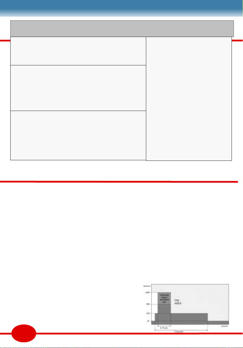
Force tesng
EN12445 explains the method of tesng the
impact forces of a gate. The crux is a graph of
acceptable forces from the point of impact.
Safety device applicaons
Safety devices such as sensive edges and photo
beams are to stop, and if necessary, reverse the
gate movement in the “Risk Zone”. Applicaons
necessary for safety are primary devices. Other
applicaons that contribute to safety, but are
not necessary are supplementary devices. Some
devices are only rated for supplementary safety
use. Primary devices need to be Cat2 or Cat3 as
dened by EN954-1.
Gate Safety Code of Pracce
Installaon record
Installaon Sengs
DIPs
POTs
Safety
ON ON ON ON ON ON ON ON
FORCE % LV % RV %
Authorised Users
1
2
3
4
5
6
7
8
Input Posion Device
IR1 FA31
Acvaon
Input Posion Device / code
13

Crush hazards marked C1 to C3
Crushing is between a moving part and a staonary
part. It is most signicant below 500mm when it
may be up to 400N for less than 750ms. Moving
part needs to be less than 25N within 5 secs.
Impact zones marked R1 to R3
Impact refers to a moving object striking a person
outside the crush zone. This is 1400N for less than
750ms. There could be a temporary object (a car) in
the R zones, hence the use of photobeams.
Safety distances marked S1 & S2,
At least one photobeam 300—700mm high must
supplement force limitaon. Spacing between the
beams and the limit of the moving part must be less
than 200mm. Nominal spacing between vercal
gate bars is 100mm. Safety must be eecve to H,
the maximum height of the moving part, or 2.4m,
whichever is the least.
Edited from DHF TS 011 Code of Pracce
‘Draw in’ or Shear Gaps where a body
part could be drawn in are not allowed. Limbs have
dierent nominal sizes. Finger gaps need to be less
than 8mm (D2), arms less than 100mm etc. A solid
inll sliding gate needs to be less than 8mm from
the post. Vercal bars on sliding gates (D2) present
mulple shear risks against the supporng post.
Entrapment Ez is an area where a
person can be entrapped without being in contact
with the gate. Entrapment is not permied unless a
manual release is provided inside the zone.
Finger traps F1 is a nger trap as a result
of poor hinge design. Designs must ensure moving
gaps are under 100mm, and either under 4mm or
over 25mm, and the gap changes by less than 20%.
Motor PSR is not an acceptable nger trap soluon.
‘Hold to run’ speed of a closing gap in a crush zone
must be less than 0.5m/s. Gates must stop within
50mm in the crush zone, or 100mm at mid travel.
14

RETRO
Complete your home security with
a Foresee gate automation set
PICO
sliding gate motors for
confined spaces, sloping
drives, and sharp corners
AVANTI
Warranty
Warranty covers defects to the Foresee product proven attributable
to a material or manufacturing fault during the warranty period. We
will repair, or refund, or replace faulty product with a similar fault
free product at our discretion. We do not accept costs for
dismantling, installation, or for carriage. Parts replaced under
warranty are the property of the warrantor.
Warranty only covers damage to the contract object. A warranty
card and a dated proof of purchase through an authorized agent is
required. Warranty covers safe reliable function of this set for 3
years from the date of purchase.
The warranty period for Radio Equipment is 24 months. The period
for replacement parts is 6 months or to the end of the current
warranty period, which ever is longer.
Warranty exceptions
The warranty does not cover damage caused through:
Wear & Tear or Improper Installation or Negligent Care or lack of
Maintenance or Misuse or Water ingress or Abnormal
Environmental Influences or Mechanical damage during Transport
or damage through improper Installation or Additional Surface
Protection treatment or mis-repair by Non-qualified or Incompetent
Persons or unapproved parts or Removal of Product Identification.
PRIMO
Garage door opener
This manual suits for next models
2
Other Forematic Gate Opener manuals


