manuals.online logo
Brands
  1. Home
  2. •
  3. Brands
  4. •
  5. Fab Fours
  6. •
  7. Automobile Accessories
  8. •
  9. Fab Fours X595X User manual

Fab Fours X595X User manual

Installation manual
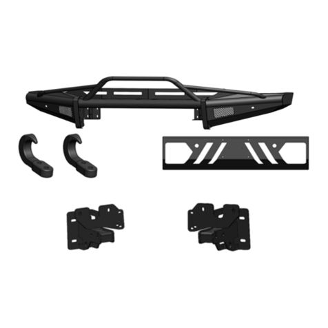
matrix Front Bumper
Product number: X595X
Application: 2023 FORD SUPER DUTY
IMPORTANT SAFETY GUIDE | Your safety and the safety of others is very important.
SAFETY PRECAUTIONS
In order to help you make informed
decisions about safety, we have provided
the following warnings, safety precauons,
installaon instrucons, and other important
informaon to alert you to potenal hazards
that could hurt you or others.
Please do a job safety analysis before each
task to idenfy potenal hazards for your
situaon and remove/protect against them.
Use own good judgment and take your me.
• Failure to observe the following warnings
and instrucons provided in this manual
could lead to severe injury and/or death.
• For professional installaon only. Careless
installaon and/or operaon can result in
serious injury, death, and/or equipment
damage. All liability for installaon and use
rests with the user or consumer.
WARNINGS
• Always remove jewelry and wear eye
protecon.
• Always use extreme cauon when jacking
up a vehicle for work. Set emergency brake
and use re blocks. Locate and use the
vehicle manufacturers designated liing
points. Use jack stands.
• Always use appropriate and adequate care
in liing components into place.
• Always ensure components will remain
secure during installaon and operaon.
• Always wear safety glasses when installing
this kit. A drilling operaon will cause
ying metal chips. Flying chips can cause
serious eye injury.
• Always use extreme cauon when drilling
a vehicle. Always disconnect power before
welding. Thoroughly inspect the area to
be drilled (on both sides of material when
possible) prior to drilling, and relocate any
objects that may be damaged.
Check packaged materials immediately upon
arrival to ensure that all listed parts are included
and undamaged.
Read and understand all warnings, safety
precauons, and instrucons before installing
this product.
SENSORS FIELD OF VIEW MAY BE ALTERED WITH
USE OF THE REPLACEMENT BUMPER.
• Fab Fours, Inc. only approves installing this
product according to these wrien instrucons
with the hardware provided. Failure to install
according to these instrucons will invalidate
the warranty. This includes, but is not limited
to, using alternave installaon methods,
hardware, or materials.
• This product is for o road use only.
• Always use extreme cauon when welding
a vehicle. Thoroughly inspect the area to
be welded (on both sides of material when
possible) prior to welding, and relocate any
objects that may be a re hazard. When
welding in a cab, make sure the interior
surfaces are covered (e.g., welding blanket)
and a re exnguisher is at hand.
• Always use extreme cauon when cung and
trimming during ng.
• Always ghten all nuts and bolts securely per
installaon instrucons.
• Always route electrical cables carefully. Avoid
moving parts, components that become hot,
and rough or sharp edges.
• Always insulate and protect all exposed wiring
and electrical terminals.
• Perform regular inspecons and maintenance
on mounts and hardware.

Table of contents
SAFETY / DISCLAIMER
TABLE OF CONTENTS
A MESSAGE FROM THE OWNER
GETTING STARTED
PROVIDED MATERIAL
INSTALLATION
CONTACT
2
3
4
5
6
8
25
A message from the owner
Fab Fours’ was born out of a passion for customizing vehicles and a love of the outdoors. Our
engineering team uses the latest 3D design software to turn new product ideas into reality. In our
factory, designs come to life with the combination of cutting edge technology for metal cutting
and forming and an American workforce that puts its’ heart and pride into every product.
From design and manufacturing, to quality and delivery, Fab Fours’ mission is to be the market
leader for steel truck and jeep accessories. We make sure a quality product is delivered on time,
more than expected, better than expected to our customers.
Enjoy your new Fab Fours product. Welcome to the family!
Greg Higgs
Founder, Fab Fours
5
Before you begin the installation process of your new Fab Fours product, we suggest
laying out all materials and parts on a pad or protective surface.
Failure to fully account for all components before beginning installation may leave vehicle
immobile until part is acquired. Refer to the next pages as an inventory check.
Getting started
Provided materials
• PANEL PRY TOOL
• TAPE MEASURE
• SILVER MARKER
• ANGLE GRINDER OR
HAND FILE
• DRILL
• 1/4” DRILL BIT
• 1/2” DRILL BIT
• E6 TORX SOCKET
• 1/8” ALLEN WRENCH
• 8MM SOCKET WRENCH
• 11MM SOCKET WRENCH
• 15MM SOCKET WRENCH
• 18MM SOCKET WRENCH
• 7/16” SOCKET WRENCH
• 7/16” COMBINATION
WRENCH
• 3/4” COMBINATION
WRENCH
• 3/4” DEEP SOCKET
WRENCH
TOOLS REQUIRED
Disassemble the vehicle where you
can catalog and store everything.
We suggest labeling and bagging all
the OEM bolts when removing from
the vehicle. Failure to keep track of
parts could lead to an inability to
properly reinstall components.
Organization
We recommend two people
perform the installaon as items
are heavy and may need to be held
in place while installing.
assistance
23038 – BUMPER SHELL
20296 – BOLT STRIP QTY:4
21871 – LIGHT BAR L-BRACKETS
QTY:2
61784 – ACC FILLER PANEL
(PLASTIC SHEET)
61632 – EPOXY PACKETS QTY:2
50409-HW – HARDWARE KIT
23042 – ACC COVER SHROUD
23039 – DS MOUNTING BRACKET
23040 – PS MOUNTING BRACKET
23046 -WASHER PLATES
QTY 4
7
IDENTIFICATION
NUMBER
Component
Description
QTY
50409-HW 1/4"-20 X 1", HEX HEAD CAP SCREW, YELLOW-ZINC, GRADE 8 2
50409-HW 1/4"-20, HEX NUT, YELLOW-ZINC, GRADE 8 2
50409-HW 1/4"-SAE, FLAT WASHER, YELLOW-ZINC, GRADE 8 4
50409-HW 1/4"-SAE, LOCK WASHER, YELLOW-ZINC, GRADE 8 2
50409-HW 1/2"-13 X 2.0", HEX HEAD CAP SCREW, YELLOW-ZINC, GRADE 8 8
50409-HW 1/2"-SAE, LOCK WASHER, YELLOW-ZINC, GRADE 8 16
50409-HW 1/2"-SAE, FLAT WASHER, YELLOW-ZINC, GRADE 8 16
50409-HW 1/2"-13, HEX NUT, YELLOW-ZINC, GRADE 8 16
50409-HW 10-24 X 3/4", SOCKET HEAD CAP SCREW, BLACK SS 2
50409-HW 10-24, CLIP ON BARREL NUT 2
50409-HW 1-3/8", RUBBER SENSOR HOLE GROMMET 4
50409-HW PLASTIC SENSOR HOLE PLUG 4
50409-HW 1/2" BOLT RETAINER CLIP 2
Hardware kit | 50409-HW
1. Remove the plasc tow hook covers by pulling on them to release the clips. Figure 1
2. Disconnect the bumper electrical harness connected to the inside of the driver side frame rail.
Figure 2
Figure 1
Figure 2
INSTALLATION
9
3. If applicable, remove the adapve cruise control (ACC) sensor from its mounng bracket. Figure 3
4. If applicable, disconnect the electrical connector from the ACC sensor. Figure 4
Figure 3
Figure 4
5. Using an E6 torx socket remove the three (3) studs that aach the ACC bracket to the vehicle. Figure 5
6. Using an 18mm socket wrench, remove the eight (8) bolts that aach the bumper to the tow hook
brackets. Figure 6
Figure 5
Figure 6
11
7. Using a 15mm socket wrench, remove the two (2) bolts per side that aach the bumper reinforcement
brackets to the frame. Figure 7
8. Using a body panel pry tool, remove the two (2) push pins aaching the shroud to the grille. The
bumper can now be removed from the vehicle. Figure 8
Figure 7
Figure 8
9. Using an 18mm socket wrench, remove the eight (8) bolts aaching the tow hooks to the frame and
remove the tow hooks. Figure 9
10. Using an 18mm socket wrench, remove the eight (8) nuts aaching the underrun guards to the
boom of each frame rail. Figure 10
Figure 9
Figure 10
13
11. Using an 8mm socket wrench, remove the four (4) screws in each fog light bracket to remove them
from the bumper. Figure 11
12. Using a panel pry tool, remove the push pin clip. Figure 12
Figure 11
Figure 12
13. Using a marker, trace the outline and the two (2) holes of the provided ACC cover plate (Part#: 23042)
onto the smooth side of the provided plasc ACC ller panel (Part#: 61784). Then use a knife to cut the ACC
ller panel along the marked line and use a 1/4” dill bit to drill the two (2) holes previously marked. Figure
13-14
14. Hold the cut ACC ller panel inside the bumper and align the two (2) drilled holes with the
corresponding holes in the bumper. Using a marker, trace the upper hole cutout in the bumper. Figure 15
Figure 13
Figure 15
Figure 14
15
15. Remove the ACC ller panel, and use a 1/2” drill bit, drill out the previously marked spot on the ACC
ller panel. Figure 16
16. Using a tape measure and marker, measure in from the corner of the ACC mounng bracket 1/4” and
make a chamfer mark. Figure 17-19
Figure 16
Figure 17 Figure 18
Figure 19
17. Using an angle grinder or hand le, remove the material previously marked on the ACC bracket.
Figure 20
18. Dislodge the three (3) ACC bracket studs from the bracket towards the end with the lock nut so that
the ball is visible. Figure 21
Figure 20
Figure 21
17
19. Install the ACC bracket into the bumper. Figure 22
20. Thread the ACC bracket mounng studs into the mounng bracket in the bumper using an E6 torx
socket wrench. Tighten the top stud unl the sensor face is parallel to the bumper face. Figure 23A
**Note: The ACC sensor can be
adjusted for calibraon aer the
bumper is installed by simply
removing the cover plate to
access the top stud. **
Figure 22
Figure 23A
21. Install the two (2) provided barrel nuts onto the ACC ller panel and insert it inside the bumper.
Using the two (2) provided 10-24 socket head cap screws with an 1/8” Allen wrench, install the ACC cover
plate. Figure 23B
22. Using a pry tool, reset the sockets in the ACC mounng bracket onto the mounng stud balls. Figure 24
Figure 23B
Figure 24
19
23. If installing lighng in the bumper do so now. Use the two (2) provided L-brackets (part#: 21871) and
four (4) 1/4” hex cap screws, at washers, lock washers, and nuts to mount the 30” lightbar. Figure 25-27
Figure 25
Figure 26 Figure 27
24. Reinstall the front parking sensor housing, sensors, and harness into the Fab Fours bumper in the
same posion and orientaon as they were removed from the OEM bumper. Use the provided epoxy to
secure the sensor housing to the bumper shell. Zip-e the harness to the boom of the tabs welded to the
inside of the shell under the winch access holes. Figure 28-32
Figure 28
Figure 29 Figure 30
Figure 31 Figure 32

Other Fab Fours Automobile Accessories manuals

Fab Fours Vengeance V4051 User manual

Fab Fours

Fab Fours Vengeance V4051 User manual

Fab Fours S446X User manual

Fab Fours

Fab Fours S446X User manual

Fab Fours GR1005 User manual

Fab Fours

Fab Fours GR1005 User manual

Fab Fours H3250 User manual

Fab Fours

Fab Fours H3250 User manual

Fab Fours N365X User manual

Fab Fours

Fab Fours N365X User manual

Fab Fours U 4950 User manual

Fab Fours

Fab Fours U 4950 User manual

Fab Fours C3150 User manual

Fab Fours

Fab Fours C3150 User manual

Fab Fours N3250 User manual

Fab Fours

Fab Fours N3250 User manual

Fab Fours A4160 User manual

Fab Fours

Fab Fours A4160 User manual

Fab Fours VI-COWL User manual

Fab Fours

Fab Fours VI-COWL User manual

Fab Fours JTOR-02 User manual

Fab Fours

Fab Fours JTOR-02 User manual

Fab Fours H2950 User manual

Fab Fours

Fab Fours H2950 User manual

Fab Fours Vengeance Light Mesh User manual

Fab Fours

Fab Fours Vengeance Light Mesh User manual

Fab Fours JL3021-22 User manual

Fab Fours

Fab Fours JL3021-22 User manual

Fab Fours F2950 User manual

Fab Fours

Fab Fours F2950 User manual

Fab Fours Y1950 User manual

Fab Fours

Fab Fours Y1950 User manual

Fab Fours Z1550 User manual

Fab Fours

Fab Fours Z1550 User manual

Fab Fours H2340 User manual

Fab Fours

Fab Fours H2340 User manual

Fab Fours D4351 User manual

Fab Fours

Fab Fours D4351 User manual

Fab Fours VC3900 User manual

Fab Fours

Fab Fours VC3900 User manual

Fab Fours H4550 User manual

Fab Fours

Fab Fours H4550 User manual

Fab Fours M2250 User manual

Fab Fours

Fab Fours M2250 User manual

Fab Fours S496x User manual

Fab Fours

Fab Fours S496x User manual

Fab Fours CH20-E4951-1 User manual

Fab Fours

Fab Fours CH20-E4951-1 User manual

Popular Automobile Accessories manuals by other brands

Safe Fleet PRIME DESIGN VBR-TC21B manual

Safe Fleet

Safe Fleet PRIME DESIGN VBR-TC21B manual

Thule RAPID Fixpoint XT Fitting instructions

Thule

Thule RAPID Fixpoint XT Fitting instructions

Thule 1705 instructions

Thule

Thule 1705 instructions

Yakima Prorack K089 Fitting instructions

Yakima

Yakima Prorack K089 Fitting instructions

Aries S224045 installation manual

Aries

Aries S224045 installation manual

Whispbar K677W Fitting instructions

Whispbar

Whispbar K677W Fitting instructions

Lund Ventvisor installation instructions

Lund

Lund Ventvisor installation instructions

Shell newmotion Home Advanced Edition 7 instruction manual

Shell

Shell newmotion Home Advanced Edition 7 instruction manual

Cheetah GPSmirror user manual

Cheetah

Cheetah GPSmirror user manual

Dunlop L.KI.C2-C4.C.M installation manual

Dunlop

Dunlop L.KI.C2-C4.C.M installation manual

Motoalliance Denali MA11705 manual

Motoalliance

Motoalliance Denali MA11705 manual

Wentronic goobay 44176 user manual

Wentronic

Wentronic goobay 44176 user manual

Prime Design UVX 201 Assembly instructions

Prime Design

Prime Design UVX 201 Assembly instructions

Toyota TSN 300 Corolla E12 L Series installation instructions

Toyota

Toyota TSN 300 Corolla E12 L Series installation instructions

Aries 204017 installation manual

Aries

Aries 204017 installation manual

Metra Electronics 95-5812 installation manual

Metra Electronics

Metra Electronics 95-5812 installation manual

Agri-Fab SUPER 17 owner's manual

Agri-Fab

Agri-Fab SUPER 17 owner's manual

K&K M5700N manual

K&K

K&K M5700N manual

manuals.online logo
manuals.online logoBrands
  • About & Mission
  • Contact us
  • Privacy Policy
  • Terms and Conditions

Copyright 2025 Manuals.Online. All Rights Reserved.