Fablicator FM1 User manual

User Manual
Version 1.11
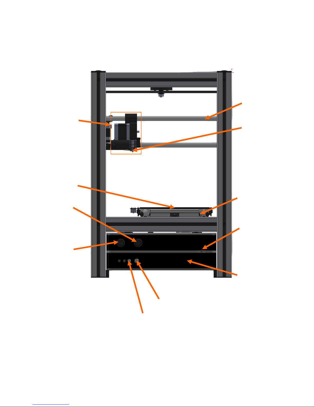
Extruder Nozzle
Heated Print Bed
Power Buon
Reset Buon
Extruder Stepper
Disable Switch
XYZ Axis Stepper
Disable Switch
USB COVER PANEL
CD/DVD Drive
Extruder Carriage
Y Axis
X Axis
The Fablicator at a Glance
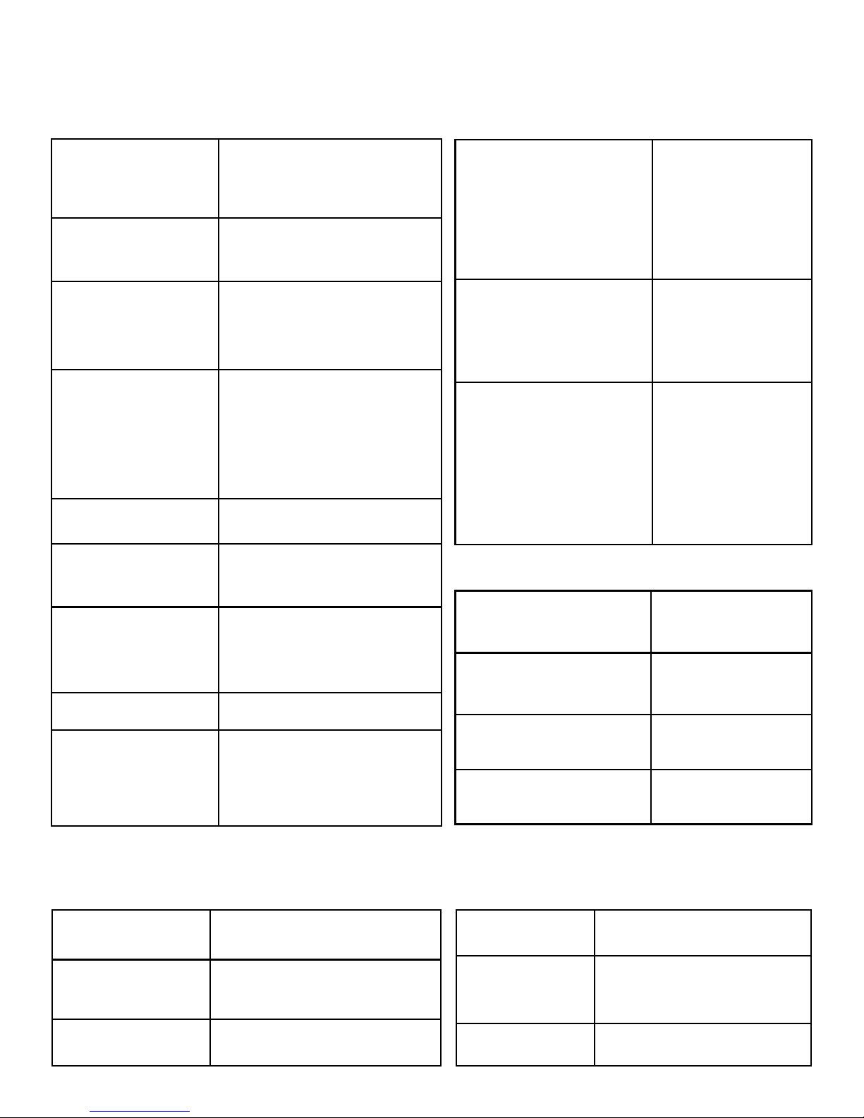
Fablicator Specicaons
Addive Technology Fused Filament Fabricaon
(commonly referred to as
FDM)
Build Volume 178 x 178 x 178 mm
(7 x 7 x 7in )
Layer Resoluons 60um—300um
125um, 175um, and 250um
are standard presets.
Mechanical Precision X 12.5um 0.0005in
Y 12.5um 0.0005in
Z 0.06um 0.000002in
Typical Part Accuracy 0.005mm/mm (+-0.005in/in)
Typical Part Precision +-.25mm (+- 0.01in )
Filament Diameter 1.75mm (.069in)
Nozzle Diameter 0.35mm (.014in)
Travel speed 25mm-300mm/s
(1- 12in/s)
AC Voltage 100-240V
Current 3.75A MAX
Waage 200W Typical During Prinng
Connecvity USB
CD/DVD
Ethernet
Wireless (oponal)
Soware KISSLicer,
Fablicator Interface
Windows 7
Computer Hardware AMD A4-4000
450W 12V PSU
2GB RAM
CD/DVD
500GB HDD
Operang temperature 12C to 32c
Storage temperature 0C to 45c
Maximum nozzle tempera-
ture
270C (520f)
Maximum bed tempera-
ture
125C (260F)
Weight 16kg (35lb)
Size with Spool 43 x 43 x 56 cm
(17 x 17 x 22in)
Waage 200W Typical During Prinng
Prinng Computer
Power Size
Temperature

Fablicator Standard Materials
ABS PLA PETGMaterial
A Mixture of Acrylonitrile,
Polybutadiene, and Polysty-
rene.
Starch based, Biodegradea-
ble plasc
A type of Polyester ResinWhat is it?
Higher temperature toler-
ance, slightly more elasc
than PLA. Most easily
drilled, tapped, sanded and
painted.
High strength and least
warping, cracking, and de-
laminaon when prinng.
Strong and impact resistant
material. Low warping,
cracking, and delaminaon.
High wear resistance.
What are it’s main
benets?
95C 60C 60CMaximum Structural
Temperatures
260C Head
125C Bed
240C Head
75C Bed
240C Head
75C Bed
Typical Prinng Tem-
perature
Opaque Most colors opaque or very
slightly translucent
Most colors semi-
translucent
Opcal Properes
Legos, Pipe, Toys Small food containers, Bio-
degradable cups, Utensils
Water Boles, Food Pack-
aging
Common real world
uses
What are the di-
cules prinng this
material?
Large parts may li o
plaorm (warp,) crack, or
delaminate easily
Small cross secon parts
may deform if not enough
me between layers
Small cross secon parts
may deform if not enough
me between layers. Oc-
casional problems with ad-
hesion to build plaorm.
Density 1.04g/cc 1.2g/cc 1.38g/cc

Fablicator Accessories:
Front Panel Calipers Allen Wrenches and Steel Wire
Rear Panel Part Removal Tool Print Primer Bole
Top Panel Standard Spool Holder Anstac Material Spool Holder
Right Panel Print Primer Pellets X3 Windows 7 Backup CD
Le Panel Filament Spool X3 Power Cord
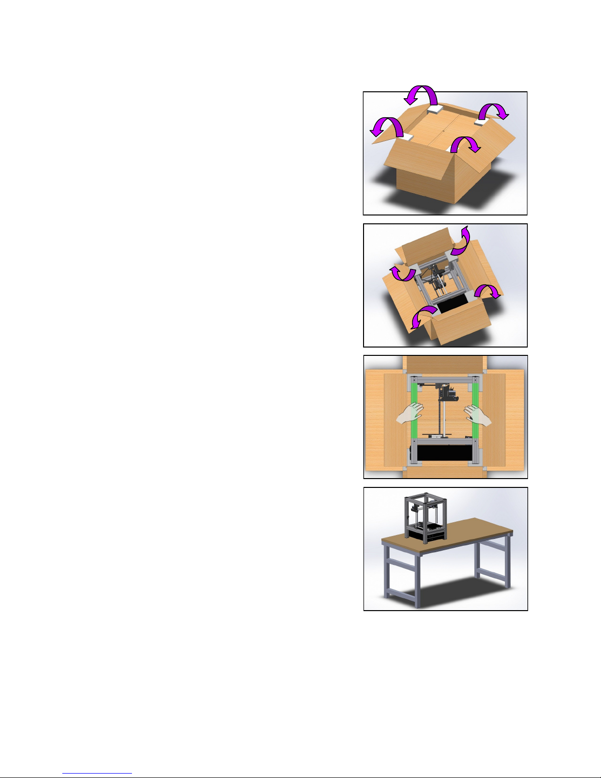
Unpacking the Fablicator
1. Open the large box containing the Fablicator, and re-
move the foam corners
2. Open the Internal box, and also remove the foam cor-
ners
3. Gently li out the Fablicator, holding it by the frame
(highlighted in green)
Some assistance may be helpful for this step
Cauon: ONLY li the Fablicator by the aluminum frame.
4. Place the Fablicator on a sturdy table or desk.
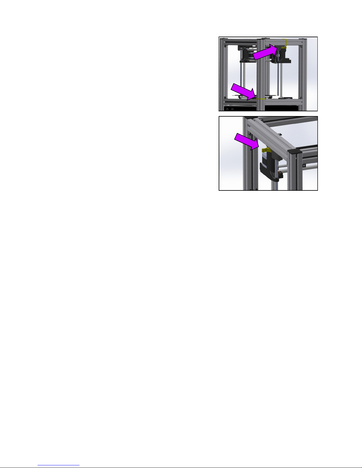
5. Carefully cut the colored zip es and remove the
yellow clips
Save the yellow axis stops in case the Fablicator ever
needs to be shipped.
Unpacking the Fablicator
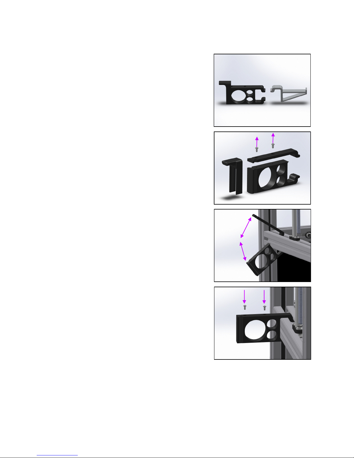
Seng up the Spool Holders
1. The Fablicator comes with two types of spool holders.
The standard spool holder (1) is for s ABS, PLA and PETG
Spools.
The alternate holder (2) is designed for anstac material
spools
2. Remove the screws from the standard spool holder, so
it can be aached to the printer.
3. Slide and Rotate the spool holder halves into the ex-
trusion frame.
4. When the two halves are brought together, insert and
ghten the screws.
(1) (2)
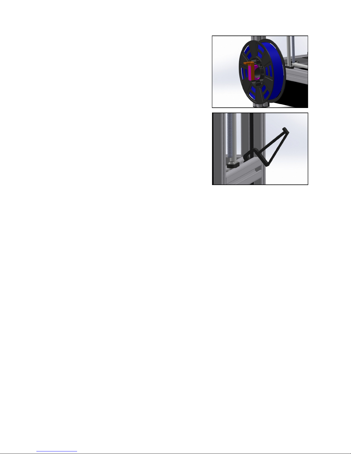
5. A spool slides onto the holder and the clip is inserted
to secure it.
6. The anstac spool holder is simply inserted and ro-
tated into place on the opposite side of the printer.
Seng Up the Spool Holders
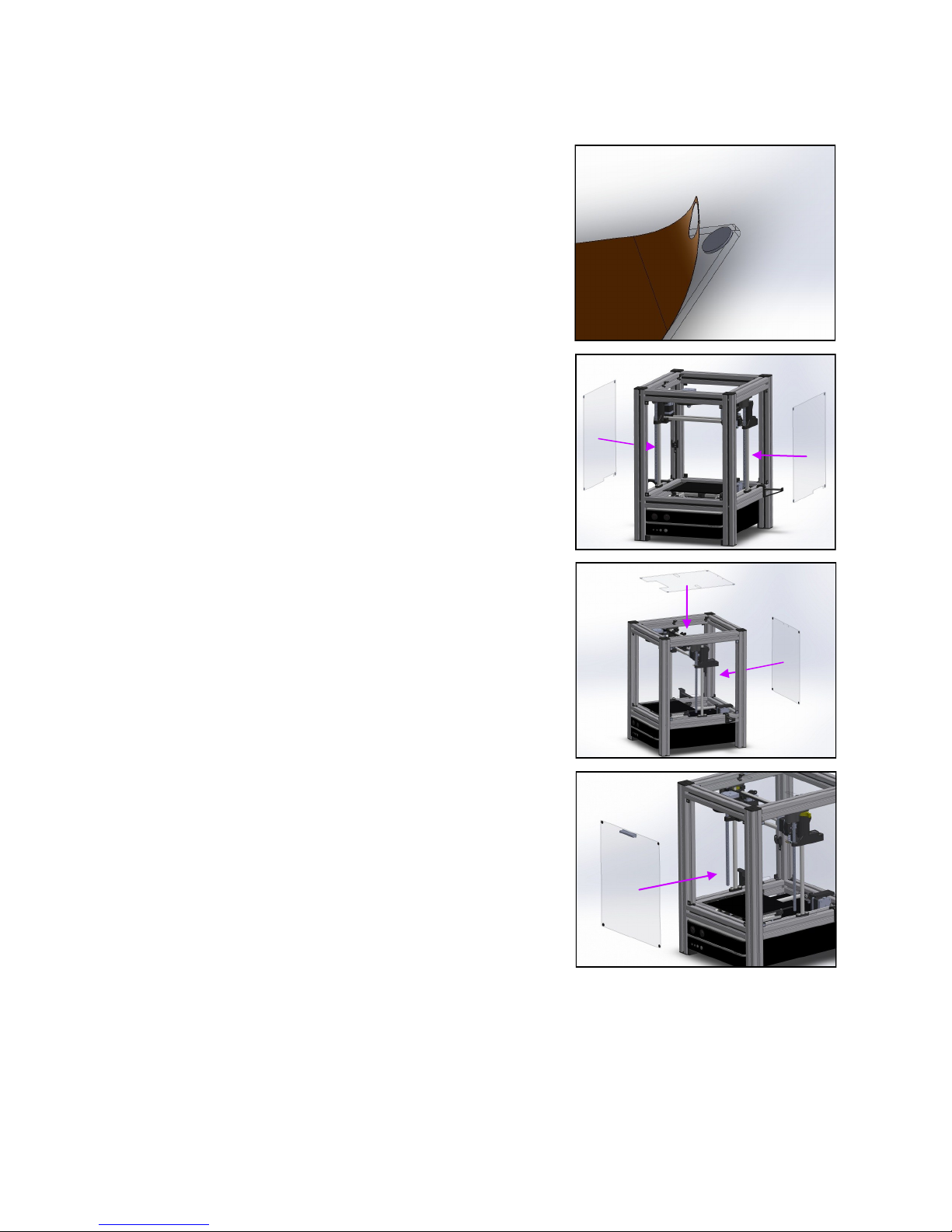
Aaching the Exterior Panels
1. Remove the protecve lm from the 5 exterior panels.
2. Aach the side panels, with the small notch aligning
with the spool holder. The magnets on the panel should
seat to the magnets on the frame
3. Aach the top and rear panel
4. Aach the front panel
*If addional handles are desired, the .stl le is available in
the sample .stl folder on the Fablicator’s desktop.
Table of contents
Other Fablicator 3D Printer manuals


