fadini BAYT 980 User manual

EN 13241
EN 12453
EN 12445
1 - 24GB Instructions manual pages
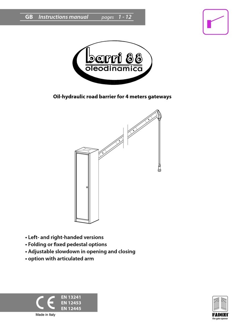
Oil-hydraulic road barrier for trac control from 3 to 8 metres
• Stainless steel and painted versions
• Version with aluminium fence
• Version with articulated beam
• Folding or xed leg with forked end
• Fully convertible into right or left versions
• Pre-set braking on opening and adjustable on closing
• Beams with ashing led lamps on request
Oil-hydraulic
the gate opener

2
oil-hydraulic barrier
BAYT 980
GENERAL WARNINGS FOR PEOPLE SAFETY
INTRODUCTION
This operator is designed for the specic scope of applications
as indicated in this manual, it includes safety, control and
signaling accessories as minimum required and FADINI
equipment. □Any applications not explicitly included in this
manual may cause operation problems or damages to
properties and people. □Meccanica Fadini snc is not liable for
damages caused by the incorrect use of the equipment, or for
applications not included in this manual or for malfunctioning
resulting from the use of materials or accessories not
recommended by the manufacturer. □The manufacturer
reserves the right to make changes to its products without
prior notice. □All that is not explicitly indicated in this manual
is to be considered not allowed.
BEFORE INSTALLATION
Before commencing operator installation assess the suitability
of the access, its general condition and the structure. □Make
sure that there is no risk of impact, crushing, shearing,
conveying, cutting, entangling and lifting situations, which
may prejudice people safety. □Do not install near any source of
heat and avoid contacts with ammable substances. □Keep all
the accessories able to turn on the operator (transmitters,
proximity readers, key-switches, etc) out of the reach of the
children. □Transit through the access only with stationary
operator. □Do not allow children and/or people to stand in the
proximity of a working operator. □To ensure safety in the
whole movement area of a gate it is advisable to install
photocells, sensitive edges, magnetic loops and detectors. □
Use yellow-black strips or proper signals to identify dangerous
spots. □Before cleaning and maintenance operations,
disconnect the appliance from the mains by switching o the
master switch. □If removing the actuator, do not cut the
electric wires, but disconnect them from the terminal box by
loosening the screws inside the junction box. □Make sure that
in the near proximity or inside the installation accessories there
aren’t any electromagnetic sources of disturbance, such that
they can cover or aect the magnetic/electromagnetic
detections of possible loop detectors as well as of all of the
electronic units that command and control the system.
INSTALLATION
All installation operations must be performed by a qualied
technician, in observance of the Machinery Directive
2006/42/CE and safety regulations EN 12453 - EN 12445. □
Verify the presence of a thermal-magnetic 0,03 A - 230 V - 50 Hz
circuit breaker where the main electric source of power of the
installation is located. □Use appropriate objects to test the
correct functionality of the safety accessories, such as
photocells, sensitive edges, etc. □Carry out a risk analysis by
means of appropriate instruments measuring the crushing and
impact force of the main opening and closing edge in
compliance with EN 12445. □Identify the appropriate solution
necessary to eliminate and reduce such risks.
□During the rotation of the beam there must not be obstacles
or points of contact that interfere with the movement.
□In case where the gate to automate is equipped with a
pedestrian entrance, it is appropriate to prepare the system in
such a way to prohibit the operation of the engine when the
pedestrian entrance is used. □Apply safety nameplates with
CE marking on the gate warning about the presence of an
automated installation. □The installer must inform and
instruct the end user about the proper use of the system by
releasing him a technical dossier, including: layout and
components of the installation, risk analysis, test of safety
accessories, test of impact forces and report of residual risks.
INFORMATION FOR END-USERS
The end-user is required to read carefully and to receive
information concerning only the operation of the installation
so that he becomes himself responsible for the correct use of it.
□The end-user shall establish a written maintenance contract
with the installer/maintenance technician (on -call). □Any
maintenance operation must be done by qualied technicians.
□Keep these instructions carefully.
WARNINGS FOR THE CORRECT OPERATION OF THE
INSTALLATION
To achieve a long lasting performance of system in compliance
with the safety regulations, it is necessary that proper
maintenance and monitoring of the entire installation be
performed: including the automation, the electronic
equipment and the cables connected to these. □The entire
installation must be carried out by qualied technical
personnel, lling in the Maintenance Manual indicated in the
Safety Regulation Book (to be requested or downloaded from
the site www.fadini.net/supporto/downloads).
□Operator: maintenance inspection at least every 6 months,
while for the electronic equipment and safety systems an
inspection at least once every month is required. □The
manufacturer, Meccanica Fadini snc, is not responsible for
non-observance of good installation practice and incorrect
maintenance of the installation.
DISPOSAL OF MATERIALS
Dispose properly of the packaging materials such as
cardboard, nylon, polystyrene etc. through specializing
companies (after verication of the regulations in force at the
place of installation in the eld of waste disposal). Disposal of
electrical and electronic materials: remove and dispose
through specializing companies, as per Directive 2012/19/UE.
Disposal of substances hazardous for the environment is
prohibited.
CE DECLARATION OF CONFORMITY of the manufacturer:
Meccanica Fadini snc (Via Mantova, 177/A - 37053 Cerea - VR - Italy) declares under own responsibility that: Bayt 980 complies
with the 2006/42/CE Machinery Directive, and also that it is sold to be installed in an “automatic system”, along with original
accessories and components as indicated by the manufacturing company. An automatic gate operator is, by law, a“machinery”
and therefore the installer must t the equipment with all of the applicable safety norms. The installer is also required to issue
the installer’s Declaration of Conformity. The manufacturer is not liable for possible incorrect use of the product. The product
complies with the following specic norms: analysis of the risks and subsequent action to cure them as per EN 12445 and EN
12453, Low Voltage Directive 2014/35/UE, Electromagnetic Compatibility 2014/30/UE. In order to certify the product, the
manufacturer declares under own responsibility the compliance with the EN 13241-1 PRODUCT NORMS.
English
Meccanica Fadini s.n.c.
Director in charge

3
English
BAYT 980
Pic. 1
Pic. 2
1
2
3
5
8
9
10
6
7
1. Miri 4 asher with Birio A8 aerial (optional)
2. Housing cabinet cover
3. Accessory box with Elpro 980 control unit
4. Cos 982 main assembly with hydraulic piston and oil reservoir
5. Barrier cabinet - right hand version
6. Cabinet door switch for general electrical power disconnection
7. Anchor plate with anchor bolts
8. R532 beam arm in anodised aluminium, made up of two modules: 2,10 m + 3,20 m
9. Folding leg (optional)
10. Fixed pedestal with beam catcher (optional)
Bayt 980
- internal view
Left - LH Bayt 980
- internal view
Right - RH
MAIN ELEMENTS FOR THE INSTALLATION OF A ROAD BARRIER BEAM
RECOGNITION OF THE RIGHT AND LEFT HANDED BAYT 980
External
entrance
Internal side
of the closure of the driveway
The Bayt 980 trac control barrier is distinguished
in right handed or left handed versions according
to how it is observed from outside the installation:
in any case the opening thrust of the hydraulic
piston must always lift the barrier beam (Pic. 2).
oil-hydraulic barrier
4

4
INSTALLATION OF THE ANCHORING PLATE INTO THE GROUND
The rst operation to be carried out is the cementing of the anchor plate into the ground on a levelled surface obtained through
the pouring of a cement slab, paying attention that the longer side corresponds to the cabinet door side. It is necessary then to
arrange one or two ex conduit tubes with a 50 mm diameter, which will enable the later passage of the electrical service cables
(electrical powering of the system and for the command and safety accessories), as illustrated in Pic. 3.
INSTALLATION OF THE ANCHORING PLATES FOR TWO BARRIERS
For installations that require two Bayt 980 roadway barriers it is necessary to arrange an underground electrical conduit
between the two housing cabinets, for the connection of the photocells or other accessories and for the service cabling (Pic. 4).
English
Right - RH
Left - LH
~ 500 mm
354 mm
~ 500 mm
304 mm
BAYT 980
Pic. 3
Pic. 4
~ 600 mm
65 mm
5 mm
Roadway pavement
Ø 50
Ø 50
Ø 50
Ø 50
Four M14 anchor bolts
!
Important: screw the anchor bolts into the anchor plate before cementing it in its site, so that the
respective threads protrude completely.
Important: the anchor plate must be perfectly levelled before it is cemented. Use a level in both directions
to achieve alignment. Furthermore, it must be set 5 mm higher than the level of the roadway pavement
(Pic. 3).
oil-hydraulic barrier

INSTALLATION OF THE FIXED PEDESTAL WITH BEAM CATCHER
With the installation of the xed pedestal with beam catcher, it is necessary to lay down a service conduit between the barrier and
the xed pedestal for the passage of the electrical cables of the photocells or a possible magnetic lock (optional) to secure the
aluminium barrier beam; this operation must be performed after having set the Bayt 980 foundation plate, where the edge lines
of the barrier housing cabinet and xed pedestal base plate respectively must be perfectly aligned (Pic. 6).
FIXING THE HOUSING CABINET
Once satised the anchor plate has rmly set into the ground (it is necessary to wait until the concrete has hardened), the Bayt 980
housing cabinet can be mounted onto it and then the four M14 hexagonal nuts can be securely tightened with their respective
washers (onto the anchor bolts protruding from the base of the cabinet) as illustrated in Pic. 5.
5
English
BAYT 980
Pic. 5
Pic. 6
!
Important: at the time the housing cabinet is mounted on top of the anchor base plate, make
sure that the electric cable conduits be inserted as well into the two holes in the housing cabinet
base.
Align the edge lines of the barrier housing and pedestal base plate
Ø 50 Ø 50 Ø 30
Ø 30
!
Insert the conduit inside of the cabinet
passing through the two holes in the
anchor base plate
Tighten the four M14 hexagonal nuts
with the washers supplied with the equipment
Derivation well
oil-hydraulic barrier

!
General layout: it is the installer’s responsibility to lay the connection pipes
and tubes as properly and correctly required.
Important: the entire system must be connected to earth.
!
Important:
Once the Bayt 980 has been obtained as
desired, it is nessary to:
Invert the limit switch connections for
opening and closing in the electronic
programmer terminals.
6
MAIN COMPONENTS FOR THE BAYT 980 ELECTRICAL SYSTEM
IMPORTANT: All of the electrical connections and cabling must be carried out to the rules of the art, in observance of the good
technique of installation, according to the safety regulations in force (Machine Directive 2006/42/CE) and must be performed by
qualied technical personnel, formulating a complete risk analysis and adopting suitable safety measures in the lling out of the
technical le, according to the to the EN 12445 and EN 12453 regulations. For the electrical power supply of the electric motor and
the asher, electrical cables with a section of 1 mm² will have to be utilised for a maximum distance of 50 metres. For distances
longer than 50 metres, it is recommended that cables with sections suitable for a proper standard of installation be used. For all of
the accessories external to the electrical control panel, electrical cables with wires of a section of 0,5 mm² may be utilised.
HOW TO TURN A LEFT HANDED BAYT INTO A RIGHT HANDED BAYT AND VICE VERSA
This operation is necessary in case a previously supplied Bayt 980 be required to be converted to meet the installation requirements
or on the customer’s request.
English
BAYT 980
Pic. 7
Pic. 8
1
2
3
4
5
6
7
8
n° 2x0,5 n° 3x1
1. 230 V - 50 Hz, 0,03 A magneto-thermic dierential line switch
(not provided by the manufacturer). Beyond 100 m distance, cable section to be 2,5 mm²
2. Miri 4 asher with Birio A8 aerial
3. Chis 37 built-in key-switch
4. Fit 55 built-in photocell receiver
5. Bayt 980 hydraulic barrier with Elpro 980 programmer
and Vix 53/2 R plug-on radio card
6. Pedestal with beam catcher
7. Fit 55 built-in photocell projector
8. Post with photocell
9. Vix 53/4 TR transmitter
LH
RH
Left - LH Right - RH
Actuation connecting rods
oil-hydraulic barrier
9

R532 R532
21
POSSIBLE COMBINATIONS: the R532 barrier beam is
provided in two modules: of 2,10 metres and of 3,20
metres, with the possibility of making up barrier beams of
dierent lengths, as represented in the table in Pic. 11.
7
English
BAYT 980
Pic. 9
Pic. 11
Pic. 10
INSTALLATION OF THE BARRIER BEAM AND POSSIBLE COMBINATIONS
The R532 aluminium barrier beam is attached to the
beam clamp located on the side of the housing
cabinet, facing the entrance that is to be controlled
with the barrier. To perform this operation it is rst of
all necessary to loosen the eight attachment screws in
the beam clamp and then insert the barrier beam, so
that the end with the black plastic cap extends slightly
beyond the clamp, and then nally tighten the
attachment screws (Pic. 9).
In particular situations, it might be necessary having
to remove the clamp in order to t the beam.
Beam clamp with
8 attachment screws
R532 aluminium barrier beam
Led signal lamp
always lighted
R532 aluminium barrier beam
Loosen the screws located underneath
the coupling clamp
Insert the coupling clamp to the halfway point
(note the horizontal arrow indicators)
Actual length
maximum dimensions - X
(metres)
Net length
for the roadway - L
(metres)
Insert the other barrier beam section until it
contacts the rst and then tighten the clamp screws
Barrier beam 3,20
Barrier beam 2,10 + 2,10 = 4,20
Barrier beam 3,20 + 2,10 = 5,30
Barrier beam 3,20 + 3,20 = 6,40
Barrier beam 3,20 + 2,10 + 2,10 = 7,40
Barrier beam 3,20 + 3,20 + 2,10 = 8,50
2,85
3,85
4,95
6,05
7,05
8,15
Coupling clamp
R532
2,10 metres
R532
3,20 metres
3
Net length L
Actual length X
oil-hydraulic barrier
The union of the two barrier beams is possible utilising the coupling clamp, which has the characteristic of expanding when
the screws are tightened and contracting when the screws are loosened (Pic. 10).
Union of the two R532
barrier beams with the
expandable coupling clamp

In installations in which the folding leg is required, it is
necessary to insert in the specic slot in the bottom of the
R532 barrier beam a 15 cm rubber prole (so as to cushion
the shock in the opening phase of the barrier beam) and
then the folding leg, by way of its specic attachment. Then
tighten everything with the setscrew (Pic. 12).
In the event that a fence is to be installed, it is also
necessary to attach the coupling plate between the leg
and the fence by means of nuts and bolts (Pic. 13).
15 cm rubber
prole
Barrier beam cap
Setscrew
Coupling plate
Folding leg
R532
R532
8
ATTACHMENT OF THE BAYT 980 FOLDING LEG
INSTALLATION OF COUNTERWEIGHTS ON THE BAYT 980
In Bayt 980 installations with beams that are 6,40 metres in length or longer and ttted with a fence, it is necessary to also attach
counterweights by means of nuts, bolts and a support bracket (Pic. 14).
See the summary table of the possible applications (Pic. 32, page 18).
English
BAYT 980
Pic. 13Pic. 12
Pic. 14
R532 aluminium
barrier beam
4,20 metres
5,30 metres
6,40 metres
7,40 metres
8,50 metres
R532 barrier beam
with aluminium fencing
3,80 metres
4,75 metres
5,89 metres
6,84 metres
7,98 metres
12
3
4
R533 reinforcement arm - 3,0 metres
Galvanised M8 nut
R532 anodised
aluminium beam
Barrier beam cap
Folding leg
8x65 TE galvanised screws
Barrier beam cap
Nuts
Counterweights
(10 kg each)
Attachment bolts
Counterweight
attachment support
Aluminium fencing
STANDARD MODULES
D= 2,09 m
E= 1,71 m
F= 0,57 m
oil-hydraulic barrier

For those installations where one or two magnetic loops are required, it is recommended to
follow the instructions included with the detector (Ref. drwg. 7038).
Ceiling
5 cm
1.090
900
840
24 cm
Hinge Barrier beam B
Barrier beam A
H
C = A + B
L
The B barrier beam is provided in lengths of 2,10 metres or
3,20 metres according to width C as required.
Where C is the sum of A+B.
In case a BAYT 980 with articulated arm is required at the
time of the order, it comes factory-preset for it (Ref.
Drawing 5257).
9
English
BAYT 980
Pic. 15
Pic. 16
ATTACHMENT OF THE HINGED BARRIER BEAM TO THE HOUSING CABINET
According to the demands of the installation it is possible to apply a hinge coupling to Bayt 980 following the instructions in
Pic. 15.
INSTALLATION OF THE BAYT 980 WITH MAGNETIC LOOP
Ceiling
height
H
2,50 m
2,70 m
2,80 m
3,00 m
3,70 m
4,10 m
Barrier beam
length
A
1,60 m
1,80 m
1,90 m
2,10 m
2,80 m
3,20 m
Opening
time
4 s
4 s
4 s
8 s
8 s
8 s
Metal cable xed length
(supplied by the manufacturer)
L
1,25 m
1,45 m
1,55 m
1,75 m
2,45 m
2,85 m
Ref. code 2037L - 6 m circumference,
pre-assembled loop.
Ref. code 2042L - 12 m circumference,
pre-assembled loop.
Ref. code 2037L - 6 m circumference,
pre-assembled loop.
Ref. code 2042L - 12 m circumference,
pre-assembled loop.
Bayt 980 Obstacle presence detector
Magnetic loop power supply
cable, total length =
10 metres from the detector
Magnetic loop power supply
cable, total length =
10 metres from the detector
oil-hydraulic barrier

10
PROCEDURE FOR DRILLING AND ATTACHING THE MIRI 4 FLASHER ON THE CABINET COVER
• Loosen and remove the three M8 attachment screws (9and 16) of the cabinet cover (6) - Pic. 18.
• Turn the cover (6) upside down and drill a 4,2 mm diameter hole in it and thread M5 the three studs (24) for the attachment of
the Miri 4 asher (1). Pic. 17.
• The central stud of the cover (23) must be drilled out with a 10,5 mm diameter bit to enable the passage of the electrical power
supply cable for the Miri 4 asher and for the possible insertion of the RG58 coaxial cable for the Birio A8 aerial - Pic. 17.
• Then run the electrical cables through the central 10,5 mm diameter hole and attach the vertical coupling (5) of the Miri 4 asher
(1) with the three M5 screws (4) on the outside of the cover - Pic. 18.
• Replace the cover on the housing cabinet (17) and attach it with the three M8 screws so as to cover the Bayt 980 cabinet, as shown
in Pic. 18.
In order to install the Fit 55 photocells and the Chis 37 key-switch on the housing cabinet, it is necessary to remove the
protective covers (22) unscrewing the M8 nut (20) from inside of the cabinet and then removing the stop plate (21) - Pic. 19.
The housing cabinet is in this way prepared for the attachment of all of the operational accessories - Pic. 18.
English
BAYT 980
Pic. 18
Pic. 17
Pic. 19
1
2
3
4
5
6
7
8
9
10
11
12
13
14
15
16
23 24
17
18
19
22
20
21
VIEW OF THE COVER FROM BELOW
n° 4x1
n° 4x1
1. Miri 4 asher with Birio A8 aerial (optional)
2. Miri 4 asher cable with 2x1,5 wires
3. RG58 aerial cable
4. M5 screws (3 pieces)
5. Vertical coupling for Miri 4
6. Cover to disassemble, once the three attachment screws
for the Bayt 980 are removed
7. Control box with Elpro 980 electronic programmer
8. Limit switch with spring feeler
9. M8x16 TSEI Stainless Steel screws (2 pieces)
10. Limit switch cover
11. M6x25 TEI galvanised screw (1 piece)
12. Limit switch spring
13. Door lock
14. Door
15. Cabinet door switch for general electrical power disconnection
16. M8x16 TBEI Stainless Steel screw (1 piece)
17. Bayt 980 housing cabinet
18. Chis 37 key- switch (optional)
19. Fit 55 photocell (optional)
20. M8 nut
21. Lateral cover stop plate
22. Protective lateral cover
23. Ø 10,5 central stud drill hole
24. Ø 4,2 - 3 studs drill holes
oil-hydraulic barrier

11
English
BAYT 980
Pic. 20
ELECTRICAL CONNECTIONS FOR 1 BAYT 980 TO THE ELPRO 980
PROGRAMMER
The main assembly Cos 982, voltage disconnector, limit switches
and blue led light are factory pre-set. For a detailed explanation of
all of the functions, including the automatic/semiautomatic
operating modes, hold - on - switched command and clock
connection, it is suggested that the Elpro 980 instructions book be
referred to.
COMMON
F2
F1
F3
16 17 18 19 20 21 22
16 17 18 19 20 21 22
1 2 3 4 5 6 7 8 9 10 11 12 13
1 2 3 4 5 6 7 8 9 10 11 12 13
63 64 65 66 60 61
Fuse 1 A
Red
Yellow
Green
27 28 29 23 24
27 28 29 23 24
PHASE
External
power supply
230 V - 50 Hz
Drive unit COS 982
PHOTOCELL AND
SAFETY EDGES
Red
Yellow
Green
Common
External 230 V - 50 Hz
electrical power supply
TRAFFIC LIGHTS
WITH 3 LAMPS
COMMON
COMMON
OPEN
CLOSE
OPEN
CLOSE
STOP
RADIO
CLOSING LIMIT SWITCH
OPENING LIMIT SWITCH
OUTPUT 24 V ~ 350mA max load:
2 pairs of photocells
1 Radio receiver
BLUE LED attached to the cabinet
24 Vdc - 150 mA
Output for connection
to 2nd Elpro 980
for the 2nd BARRIER
WARNING LAMP LIGHTED 24 V - 3 W
- Vertical barrier beam -
COMMON LIMIT SWITCH
NEUTRAL
FLASHER
230 V - 25 W max
MOTOR
already connected
LIMIT SWITCH
already connected
BLUE LED
already connected
POWER
DISCONNECTION
already connected
M
oil-hydraulic barrier

Trac lights PCB Trac lights
PCB connector
Plug-on
radio receiver
connector
Plug-on
radio receiver
connector
12
ELECTRICAL CONNECTIONS FOR 2 BAYT 980s TO
ELPRO 980 PCBs
English
BAYT 980
!
Important: before completing all of the electrical
connections as required, identify the Elpro 980 of the
master barrier, which commands the Elpro 980 in the
slave barrier.
In the case of simultaneous barriers it is suggested
that they are set with an equal barrier beam length
and speed, otherwise the master barrier between the
two must be that with the longer barrier beam length
or that with the slowest speed.
• Elpro 980 master: perform all of the connections necessary for the operation of the Bayt 980; any command accessories, radio
PCB etc. must be connected exclusively to the Elpro 980 master.
• Elpro 980 slave: power the PCB, jump the NC connections (stop, photocell and safety switches) and nally connect the motor
and the limit switches of the Bayt 980 slave. Set the dip-switch 12 = ON.
• Connect the 27, 28, 29 terminals of the Elpro 980 master respectively with the 3, 4, 5 terminals of the Elpro 980 slave.
Elpro 980 master PCB Elpro 980 slave PCB
63 64 65 66 60 61
Fuse 1 A
Red
Yellow
Green
1 2 3 4 5 6 7 8 9 10 11 12 13 27 28 29 23 24
27 28 29 23 24 23 24
1 2 3 4 5 6 7 8 9 10 11 12 13
1 2 3 4 5 6 7 8 9 10 11 12 13 1 2 3 4 5 6 7 8 9 10 11 12 13
PHOTOCELL AND
SAFETY EDGES
COMMON
OPEN
CLOSE
STOP
RADIO
CLOSING LIMIT SWITCH
OPENING LIMIT SWITCH
OUTPUT 24 V ~ 350 mA max load:
2 pairs of photocells
1 Radio receiver
BLUE LED attached to the cabinet
24 Vdc - 150 mA
COMMON LIMIT SWITCH
CLOSING LIMIT SWITCH
OPENING LIMIT SWITCH
OUTPUT 24 V ~ 350 mA max load:
2 pairs of photocells
1 Radio receiver
COMMON LIMIT SWITCH
16 17 18 19 20 21 22
16 17 18 19 20 21 22
PHASE
NEUTRAL
COMMON
M
16 17 18 19 20 21 22
16 17 18 19 20 21 22
PHASE
NEUTRAL
COMMON
M
23 24
BLUE LED attached to the cabinet
24 Vdc - 150 mA
Pic. 21
!Important: carry on the inter-connections
between the two Elpro 980 master and
slave PCBs
already connected
already connected
already connected
already connected
oil-hydraulic barrier
already
connected
already
connected
already
connected
already
connected

13
English
BAYT 980
ADJUSTMENT OF THE BARRIER BEAM IN HORIZONTAL AND VERTICAL POSITIONS
The Bayt 980 hydraulic barrier has a simple but eective adjustment system for the moving arm, in opening and in closing, as
indicated in Pic. 22.
ADJUSTMENT OF THE BARRIER BEAM IN CLOSING
POSITION (Pic. 23)
In closed position, the barrier beam must be horizontal;
therefore the adjustment is performed with the piston rod
completely retracted.
Before starting a new adjustment, make sure the M16
lock nut (b) be tightened hard.
1. Screw the closing limit switch feeler (a) tighter, so it is
no loger operating.
2. The M16 lock nut (d) must be loosened and then
re- adjust by a 24 mm spanner (e).
3. Tighten clockwise the adjustment nut (c) by the 24 mm
spanner so as to lower the barrier beam slightly beyond
the "horizontal line".
4. Once the adjustment has been made, the M16 lock
nut (d) previously loosened must be tightened, so as to
lock the fork to the Bayt 980 base.
5. Unscrew the closing limit switch feeler (a) until the micro-
switch snaps (when the beam is in horizontal position),
then tighten the respective M6 lock nut hard.
Pic. 23
Pic. 22
2
3
4
1
1. Closing limit switch feeler
2. Opening limit switch feeler
3. Adjustment of the opening position of the barrier arm
(adjustment ange)
4. Adjustment of the closing position of the barrier arm
(M16 counter nut and register)
!Important: once the adjustment has been made,
the M16 lock nut (d) must be tightened.
a
b
c
d
e
!Important: the adjustment of the Bayt 980 arm is factory pre-set. Make sure of the absolute necessity of changing it at
the time of the installation, and carry out some opening and closing operations before doing it.
!Important: the adjustment of the Bayt 980 arm
is factory pre-set. Make sure of the absolute
necessity of changing it at the time of the
installation, and carry out some opening and
closing operations before doing it.
oil-hydraulic barrier

14
ADJUSTMENT OF THE BARRIER BEAM IN OPENING POSITION (Pic. 24)
ADJUSTMENT OF THE LIMIT SWITCHES
Once the procedure on the stop positions of the
Bayt 980 barrier beam has been nished, it is possible
to adjust the opening and closing limit switches by
loosening the lock nuts of the adjustable ridged
feelers, which operate the exible limit switch levers.
After having veried the correct operation of the
exible lever (both in vertical and in horizontal
positions) on the limit switch micro-switch, it is
necessary to securely tighten the respective lock nuts
(Pic. 25).
1. Screw the opening limit switch feeler (a) tighter, so it is no loger operating.
2. Mechanical adjustment phase: position the beam at 45° and re-adjust by means of a screwdriver on the washer (b) posizioned
under the compression spring. Tighten the screw to the left to reduce the piston stroke (therefore the beam reaches the end of
the permitted open position earlier - vertical position); unscrew to the right to increase the piston stroke (therefore the beam
reaches the end of the permitted open position later - vertical position).
It is recommended that the limit vertical position is adjusted beyond 90°; in this way the limit switch feeler is caused to
operate before the very end of the permitted stroke.
3. Micro-switch adjustment phase: with the beam at 90° opening, unscrew the opening limit switch feeler (a) until the micro-
switch snaps; after a command pulse to open has been given, tighten the respective M6 lock nut hard.
English
BAYT 980
Pic. 24
!Important: the adjustment of the Bayt 980 arm is factory pre-set. Make sure of the absolute necessity of changing it at
the time of the installation , and carry out some opening and closing operations before doing it.
!
!
Important: at the moment of the rst
running test at the factory, the position of
the two feelers is correctly adjusted in
accordance with the vertical and
horizontal positions of the barrier beam
in opening and closing respectively.
NOT
NOT
YES
a
b
a
b
c
10
11
Pic. 25
a. Flexible limit switch lever
b. Adjustable ridged feelers
c. M6 counter nut
oil-hydraulic barrier
Important: with the barrier beam in an intermediate position at 45° and the piston rod therefore at its half stroke point,
it is possible to adjust the barrier beam in the open position. Do not adjust with the barrier beam in the vertical or
horizontal stop positions (Pic. 24).

15
English
BAYT 980
ORDINARY MAINTENANCE
Periodically it is necessary to perform maintenance to the Bayt 980 barrier and put some grease by means of the greasing nipples
factory-tted to the equipment (Pic. 26).
ADJUSTMENT OF THE THRUST FORCE
Pic. 26
1. Red screw:
adjustment of the opening thrust of the arm
2. Slowing of the barrier beam:
tightening increases the braking of the barrier
beam, loosening decreases the braking of the
barrier beam.
3. Green screw:
adjustment of the closing thrust of the arm.
4. Manual release:
in the situation in which there is an electrical
power failure, it is possible to operate the
barrier beam manual by acting on the release
valve located between the
two screws for maximum and minimum
pressure with the specic unlocking spanner;
to release: turn the release spanner in an anti-
clockwise direction (max. 1-2 turns).
!Important: at the moment of the rst running test at the factory, the thrust force is calibrated and set as a function of
the speed and the length of the barrier beam. Before changing the factory pre-set arrangements on the maximum/
minimum oil pressure screws in the valve block, make sure it is absolutely required by the site application; the two
adjusting screws, one red and one green, are positioned frontally on the valve block, at the base of the barrier beam
actuation piston (Pic. 27).
1. Bayt 980 main pivot
2. Upper attachment pin for the barrier beam
command rod-fork-connecting rod
3. Lower attachment pin for fork-reservoir-
Cos 982 piston
Pic. 27
1
3
4
2
oil-hydraulic barrier
!
Important: it is recommended that
some grease be put every three
months by the greasing nipple as
indicated in the three points in the
pictures. GREASE

16
GENERIC INSTALLATION WITH COUNTERWEIGHTS, CABLES, FENCE AND LED LAMPS
POSSIBILITY OF INSTALLATION OF THE ALUMINIUM BARRIER BEAM WITH LED LAMPS
In the event of an installation of the Bayt 980 with LED lamps, it is possible to connect the Al.Flex 34 control device and have the
lights switching on in series, or all ashing simultaneously (Pic. 29).
English
BAYT 980
Pic. 28
Pic. 29
max. 460 mm
510
8.100
(max. net length)
!Important: dimensions are variable based on the number of counterweights
attached. (See table Pic. 32, page 18).
Right - RH
1. Accessories box
2. Elpro 980
electronic programmer
3. Cable and terminals set up
inside of the housing cabinet
for the connection of the led
lamps
4. Bayt 980 housing cabinet
5. Led lamps
6. Al.Flex 34 PCB for led
control with container
2
36
1
5
4
oil-hydraulic barrier

17
English
BAYT 980
OVERALL DIMENSIONS FOR THE HOUSING CABINET AND SPECIFIC ACCESSORIES
COUNTERWEIGHT
FIXED PEDESTAL WITH FORK
R532 ALUMINIUM BARRIER BEAM COUPLING CLAMP
FOLDING LEG
ANCHOR PLATE WITH ANCHOR BOLTS
10
ø 80
304
ø 80
354
FRONT
M14
510
260
135
150
150
net length
200
135 65
3
370
2.100 300
100
3.200
Pic. 30
In zinc-coated iron.
Weight 10 kg each
Zinc-coated or stainless steel version
• Zinc-coated anchor bolts: M14x200
• Interaxis bolts holes: 200x200
• Zinc-coated or stainless steel versions
ø 70
ø 20
840
850
1.040
55
oil-hydraulic barrier
360 mm
300
510 350 65
305
415
max 460
2,85 - 3,85 - 4,95
6,05 - 7,05 - 8,15 m
1.195
220
145 805
700
900
500
980
1.090
170

6,40 4
8
14
19
Ø 40
Ø 50
Ø 60
4,20
5,30
6,40
4,20
5,30
6,40
7,40
7,40
8,50
8,50
7,40 3
4
3
6
7
9
P8
P6
P6
3
4
Ø 30
Ø 40
P16 3,20
3,20
4,20
P16
13
15
13
15
15
17
17
9
11
13
9
11
9
7
7
Specications
Speed
(s)
Piston
(mm)
No.of
counterweights
(10 kg each plate)
Reinforcement
beam
Spring Pump Fence Cable KIT
Beam
length
(m)
Applications
Leds
18
COS 982 HYDRAULIC DRIVE UNIT OVERALL DIMENSIONS
English
BAYT 980
Pic. 31
Ø 66
230 mm
180
140
370110
345
250
160
blue
brown
black
yellow/green
!
Important: do not put oil into the reservoir. It has already been lled.
To check the oil level in the reservoir of the Cos 982, the piston must be perpendicular to
the housing cabinet of the Bayt 980.
SUMMARY TABLE OF THE POSSIBLE APPLICATIONS
Pic. 32
oil-hydraulic barrier

19
oil-hydraulic barrier
English
BAYT 980
!
Important: M6 screw is the component that is
damaged following an impact and needs replacing;
see the instructions in Pic. 36.
SWING AWAY SYSTEM ALA.180 FOR THE PROTECTION OF THE BEAM AND HOUSING IN CASE OF IMPACT
ALA.180 system, accessory for BAYT 980 (item code No. 9897L), allows the opening (swinging away) of the beam in the direction of
the impact with a vehicle and has been designed to protect the main structural components of BAYT 980 barrier and beam.
Following an impact it is required that the beam be brought by hand to the original operative position, as described in the instructions
in Pic. 36.
Limitations of application with ALA.180 system:
- beam max. length (with or without LED lights): 6,40 m
- beam max. length with a fence (with or without LED lights): 4,20 m
COMPONENTS OF ALA.180 SYSTEM
Pic. 34
Pic. 33
M6 screw
Rotation hinge
Beam

20
English
oil-hydraulic barrier
BAYT 980
100
100
Ø 10
Ø 10
1) 2)
3)
!
Beam
HOW TO FIX THE BEAM TO ALA.180 SWING AWAY SYSTEM
E6
Pic. 35
Once the beam is well tted in,
tighten hard the screws of the joint.
Before tightening M10 screw and locknut, make
sure the beam is perpendicular (vertical in
opening).
Other manuals for BAYT 980
1
Table of contents
Other fadini Control System manuals
Popular Control System manuals by other brands

Stagnoli
Stagnoli E24 manual

Siemens
Siemens SINUMERIK 802S Technical manual

Pentair
Pentair IntelliSync 523404 quick start guide

Micronix
Micronix MMC-10 Series Reference manual

ViscoTec
ViscoTec Preeflow eco-CONTROL EC200-B Operation and maintenance instructions

Schweitzer Engineering Laboratories
Schweitzer Engineering Laboratories SEL-421-7 manual