rogramming:
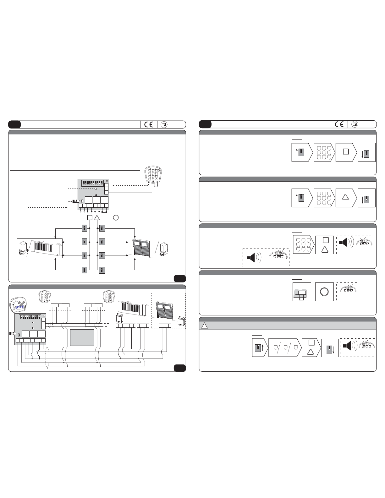
1) Set DIP-sw. 5 to ON. The red led 1 on the PCB flashes.
2) Press the number of minutes corres onding to the activation delay as
required (max.1439 minutes).
3) Press output A or B through which the required function is activated.
4) Set all the DIP-switches to OFF
Confirmation of the operation: long beep and green led alight for 2 sec.
Using the function:
Press the access code followed by A or B as programmed. The green led
goes on for 1 sec. followed by an activation beep.
The blue led starts flashing and indicates that the function has been activated.
ON
1)
5
2) 3)
OFF
4)
5
OUT UT DELAY
The pulse is delayed (for a number
of minutes) after pressin the
access code.
In order to RESET (the function is cancelled) press the followin sequence:
A or B - access code - A or B
The reen led oes on for 1 sec. followed by a confirmation beep, while
the blue led stays illuminated.
123
456
789
A
B
Dia ram
Each pulse by the access code
ener izes or de-ener izes the
output relay.
Each pulse by the access code
delays (for a number of minutes)
the ener izin of the timed relay.
pulse
output
TIMED WITH 2 ULSES
A pulse is iven after the access code
has been pressed and another one
is iven after a set time (minutes) ON
1)
6
2) 3)
OFF
4)
6
BISTABLE
Connect the main PCB to the control box (Pic. 8) or to the external control relay, then store an access code with required out uts.
Different functions can be achieved by one or both of the outputs, but different access codes to one relay carry out the same function.
NOTE WELL: functions are reset in case of a ower failure, even if instantaneous.
ON
1)
7
2) 3)
OFF
4)
7
TIMED DELAY
WITH 2 ULSES
1)
ON
8
2) 3)
OFF
8
4) 5)
The relay is ener ized and remain
ener ized for the time as set
(in minutes).
ON
1)
9
2) 3)
OFF
4)
9
6)
Steps to cancel the additional functions from the sin le relay and set the
DGT 61 unit back to normal functionin . 1)
ON
5
2)
OFF
5
3)
rogramming:
1) Set DIP-sw. 6 to ON. The red led 1 on the PCB flashes.
2) Press the number of minutes for the time required after the first ulse
(max. 1439 minutes).
3) Press either A or B output by which the function is to be activated.
4) Set all the DIP-switches to OFF.
Confirmation of the operation: long beep and green led alight for 2 sec.
Using the function:
Press the access code followed by A or B as programmed. The green led
goes on for 1 sec. followed by an activation beep.
The blue led starts flashing and indicates that the function has been activated.
123
456
789
A
B
Dia ram
In order to RESET (the function is cancelled) press the followin sequence:
A or B - access code - A or B
The reen led oes on for 1 sec. followed by a confirmation beep, while
the blue led stays illuminated.
Dia ram
7
A
B
rogramming:
1) Set DIP-sw. 7 to ON. The red led 1 on the PCB flashes.
2) Press only the button key No. 7.
3) Press either A or B output by which the required function is to be actived.
4) Set all the DIP-switches to OFF
Confirmation of the operation: long beep and green led alight for 2 sec.
Using the function:
Press the access code followed by A or B as programmed. The green led
goes on for 1 sec. followed by an activation beeping.
rogramming:
1) Set DIP-sw. 8 to ON. The red led 1 flashes.
2) Press the number of minutes for the delay with time 1 (max 1439 minutes)
3) Press either A or B output by which the required function is to be activated.
4) Press the numer of minutes for time 2 (max. 1439 minutes).
5) Press ether A or B as set in step 3).
6) Set all the DIP-switches to OFF.
Confirmation of the operation: long beep and green led alight for 2 sec.
Using the function:
Press the access code followed by A or B as programmed. The green led
goes on for 1 sec. followed by an activation beep.
The blue led starts flashing and indicates that the function has been activated.
Dia ram
A
B
A
B
In order to RESET (the function is cancelled) press the followin sequence:
A or B - access code - A or B
The reen led oes on for 1 sec. followed by a confirmation beep, while
the blue led stays illuminated.
rogramming:
1) Set DIP-sw. 9 to ON. The red led 1 on the PCB flashes.
2) Press the number of minutes corres onding to the activation time as
required (max. 1439 minutes).
3) Press output A or B as required for the function to be activated.
4) Set all the DIP-switches to OFF.
Confirmation of the operation: long beep and green led alight for 2 sec.
Using the function:
Press the access code followed by A or B as programmed. The green led
goes on for 1 sec. followed by an activation beep.
The blue led starts flashing and indicates that the function has been activated.
123
456
789
or
A
B
In order to RESET (the function is cancelled) press the followin sequence:
A or B - access code - A or B
The reen led oes on for 1 sec. followed by a confirmation beep, while
the blue led stays illuminated.
Dia ram
Dia ram
A
B
123
456
789
REMOVING THE ADDITIONAL FUNCTIONS
1) Set DIP-sw. 5 to ON. The red led 1 on the PCB flashes.
2) Press A (or B) - access code - ress A (or B).
3) Set all the DIP-switches to OFF.
Confirmation of the operation: long beep and green led alight for 2 sec.
A
B
Power supply 2x .5mm²
Connections to the keypad
Keypad absorption
Stand-by relay absorption
Energized relay absorption
Working temperature
N.O. channels
N.C. channels
Communication distance
Output contacts
kaypad protection standards
PCB protection standards
12-24Vdc/ac
4 x .5mm²
15 mA
4 mA
27 mA
-2 ° +8 °C
2
1
max 1 m
1A-125V-6 VA
IP 54
IP 53
meccanica
FADINI
ADDITIONAL FUNCTIONS: can be achieved by the A and B out uts through one or more access codes
Instructions manual DGT 61 digital keypad
GB
meccanica
FADINI
Instructions manual DGT 61 digital keypad
GB
ADDITIONAL FUNCTIONS: can be achieved by the A and B out uts through one or more access codes
TIMED BISTABLE
OVERALL DIMENSIONS
TECHNICAL DATA
The manufacturer reserves the right to change this manual
without prior notice, and is not liable for incorrect applications
or damages to persons and properties.
Pic.9
page 11 page 12
main CB time in minutes
(max 1439 = 24h)
ALL DI -SW.
TO OFF
main CB
or
output
Time 1
pulse
output
Time 2
Time
pulse
output
main CB time in minutes
(max 1439 = 24h)
ALL DI -SW.
TO OFF
main CB
or
output
main CB press key 7
ALL DI -SW.
TO OFF
main CB
or
output
Time
pulse
output
main CB
time 1 in
minutes
(max 1439)
ALL DI -SW.
TO OFF
keypad
time 2 in
minutes
(max 1439)
keypad keypad
or or
Time
pulse
output
main CB time in minutes
(max 1439 = 24h)
ALL DI -SW.
TO OFF
main CB
output
ALL DI -SW.
TO OFF
LONG BEE gree led
for 2 seconds
or
main
CB output access
code
or
output main
CB
Manufacturin company:
The model:
DECLARES UNDER ITS OWN RESPONSIBILITY THAT:
DECLARATION OF CONFORMITY
of the manufacturer
DGT 61 is a digital keypad designed to be sold and installed into a comprehensive "Automatic System",
including the original accessories and components as recommended by the Manufacturing Company.
The installer must issue the Installer's Declaration of Conformity and carry out all the tests required to
comply with the existing regulations.
The manufacturing company is not liable for any incorrect use of its product.
The product conforms with the following norms as specified below:
- Low Voltage Directive
2006/95 CE
- Electro-magnetic Compatibility Directive
2004/108/CE and 92/31 CEE
GB
DGT 61
made in Italy
the gate o ener
Date: 2 - 4- 11
meccanica
FADINI
Meccanica Fadini s.n.c.
Direttore Responsabile
The responsible manager
Via Mantova 177/A - C.P. 126 - 37 53 Cerea (VR) Italy
Tel. +39 442 33 422 - Fax +39 442 331 54
DGT 61
12-24V
cc/ca
AB
NC
X
Y
Z
91
73
27
Main
PCB
Surface mount
keypad
4
72
74
123
456
789
AB