Fairchild 63 Manual
Other Fairchild Controllers manuals

Fairchild
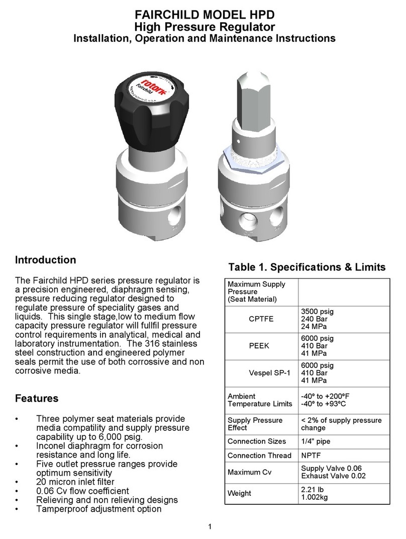
Fairchild HPD1***A**K*N Installation and operating instructions

Fairchild
Fairchild 1600A Manual

Fairchild
Fairchild T9000 User manual

Fairchild
Fairchild 1600A Manual

Fairchild
Fairchild Model 17 Manual

Fairchild
Fairchild AN-7511 Installation and operating instructions

Fairchild
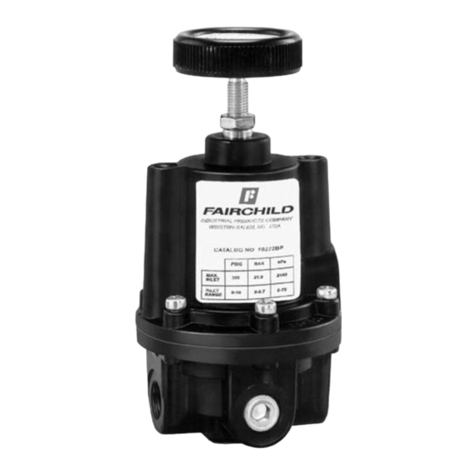
Fairchild 10BP Manual

Fairchild
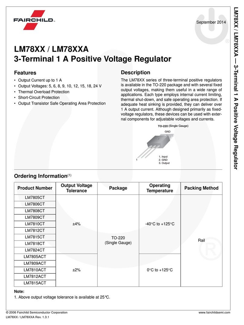
Fairchild LM78 Series User manual
Popular Controllers manuals by other brands

Digiplex
Digiplex DGP-848 Programming guide

YASKAWA
YASKAWA SGM series user manual

Sinope
Sinope Calypso RM3500ZB installation guide

Isimet
Isimet DLA Series Style 2 Installation, Operations, Start-up and Maintenance Instructions

LSIS
LSIS sv-ip5a user manual

Airflow
Airflow Uno hab Installation and operating instructions


