FAL FAL-110-CEWG User manual

1
Cooker Hood
Instruction Manual
Model No.:
FAL-110-CEWG

2
Please be careful when removing and installing the Island installation Brackets and Stainless
Steel chimneys. The Stain Less steel chimneys contains sharp edges and can possibly lead
to cuts.
Generally asked Questions and Answers:
1. Q: My extractor fan is not extracting
A: before logging a service call please ensure the installation on your extractor fans was
done properly to avoid a service call out fee charge. Herewith a list of commonly found
mistakes on everyday installations:
* Installer did not remove the tape on the butterfly valve. (Q: 13).
*Installer did not secure the power cord inside the chimney. (Q: 13).
*Your ducting hose is exceeding the recommended maximum length. (Q: 13).
*Your unit is not at the recommended height. (Q: 3).
*Your unit is installed above the wrong application. (Q: 2).
R 450.00 Service fee will apply when we log a service call and any of the points above apply.
2. Q: Can I use the extractor fan above my gas braai?
A: NO. Please note that this unit was designed for the intended purpose of domestic
kitchens only and cannot be used as a commercial extractor fan. Commercial usage
includes but is not limited to: Restaurants, Coffee Shops, Soup Kitchens, Tuck shops, Food
trailers, Gas braai’s inside or outside your property, any other form of braai and any kitchen
that is used for commercial purposes. Using the extractor you purchased on any commercial
application poses a serious fire risk and will result in immediate void of your warranty. Please
contact our Falco offices for assistance with Gas Braai Extractors.
3. Q: What is the correct installation height?
A: The recommended installation height is 750mm above gas and 650mm above electrical.
On either application it is recommended that your installation height does not exceed 750mm
to ensure the best results.
Q: Do I require a recirculation kit?
A: No. The extractor was designed to be used on both applications; External and Re-
circulation air operation and no additional kit are required.
4. Q: What is the difference between External and Re-circulation air operation?
A: Re- circulation; All wall mount units are supplied with aluminium and charcoal filters. For
Re-circulation mode you will simply install the unit. The air will filtrate through both sets of
filters, you’re outside aluminium filters and you’re inside charcoal filters.The air discharged
from your extractor is then clean and crease free and cannot cause any damage. There are
two options when using your extractor on Re-circulation. 1 – Let the filtrated air escape
through the vents on top of your top chimney or you can use the extendable ducting house
to vent the air into your ceiling.Activated charcoal in the charcoal filters removes odour
and smoke particles from the air before releasing the cleaned air back into the kitchen.
External: The only difference between Re-circulation mode and external mode is that on
external mode you are venting the air to the outside of your property using a ducting hose.
This means the clean filtrated air will not be discharged into your kitchen or ceiling but to the
outside. The unit is supplied with an extendable ducting hose. When venting your air
outwards the charcoal filters can be removed to improve the suction rate. Removing the
charcoal filters on re-circulation mode is not recommended.

3
Please note that the wall fitting that fits into your wall when venting your air outwards
is not supplied with the extractor and can be purchased locally.
5. Q: How does an Extractor Fan work?
A: Extractor fans are designed to removeairborne grease, steam, heat smoke and odours
from cooking by extracting and filtration of the air in your kitchen and above your cooking
surface.
6. Q: Are my downlights/bulbs covered under the guarantee period?
A: NO. Downlights, bulbs, aluminium and Charcoal filters and are not covered under the
guarantee period. For the full list of terms and condition of the guarantee period please read
the warranty certificate supplied inside the box or in your manual. You can also download it
from www.falco.co.za
7. Q: How often do I have to replace my filters?
A: With daily use we recommend that you replace your charcoal filters every 6 months. Your
aluminium filters can be cleaned in luke warm water and dishwashing liquid. Please do not
put your aluminium filters in the dishwasher as this will discolour the filters and they will
become dull. Alternatively you just purchase new aluminium filters.
8. Q: How long is my warranty and what does it entail?
A: All our extractor fans carry a two year guarantee. Motors, PC Boards, Capacitors,
Transformers (for units with 12volt downlights), 220Volt light sockets(for units with normal
220v light bulbs), Main Control Switches and motor fan blades are covered by our two year
parts and labour guarantee.
9. Q: What is excluded from my warranty?
A: Downlights and bulbs, Glass panels and extractor glass, aluminium and charcoal filters
are excluded from the warranty.
10. Q: How do I clean my Stainless steel extractor?
A: Always ensure your extractor is cleaned with non-abrasive cleaners. Always read the
product instructions and ensure that the product is safe for the use of Stainless steel. Two
great products are window cleaner, which is also a stainless steel cleaner, andspray on wood
polish, another certified stainless steel cleaner. Please note that abrasive cleaners will
damage the stainless steel and will cause rust or rust stains.
11. Q: Why is there rust marks on my extractor?
A: Stainless steel can rust if cleaned with abrasive cleaners. The chemicals inside abrasive
cleaners react with the stainless steel and the result will be rust.There are many day to day
cleaning products in our kitchens that are abrasive cleaners and unknown to the consumer.
Please make sure you read the instructions and if Stainless Steel is not mentioned, then do
not use the product on Stainless steel.
12. Q: Can I extend my stainless steel chimneys if they are to short?
A: Yes only on a wall mount unit. Island extractor chimneys CANNOT be extended. Please
make sure of your measurements before starting your installation process. Additional bottom
chimneys are sold by Lategan & Van Biljoens in Pretoria and they are used to extend the
chimneys on wall mount units.

4
13. Q: My extractor is blowing and not extracting?
A: There are three main reasons that can cause your extractor to blow instead of extracting
and most of the time (98%), this is caused by faulty installations. Please make sure that
there is no obstruction on top or inside your ducting hose. Make sure the power cable is
neatly secured inside the chimneys and make sure the power cable is not causing an
obstruction on top of your butterfly valve. Poor workmanship and failure to secure the power
cable causes the cable to lie on top of the butterfly valve and this will block and prevent the
unit from extracting properly.
Please ensure that the tape stuck over your butterfly valves in the factory is removed when
your unit is installed. Failure to remove the tape on the two butterfly valves will result in
airflow outlet to be restricted and this will cause the air to be returned causing the blowing of
air instead of the extraction of air. Before booking a service call make sure you check this
first to avoid being charged.
(a)This is a picture of the butterfly valve closed with the tape on top:
The tape should be removed when installed. Both butterfly valves open when the extractor is
switched on:
(b) Ducting hoses exceeding the 2.5meters will also have a negative effect on the extraction rate of
your extractor fan. If you are out-venting the air and the extension of ducting hose exceeds 2.5meter
you need to purchase an addition extraction motor that must be installed in line with the ducting hose
to support in the extraction of the air. The longer your ducting hose the less your extraction rate will
be. If your ducting hose is too long and you did not install an additional extracting motor in line with
the ducting hose, your extractor will not extract the air. Please ask your installer about an additional
inline motor when your ducting hose is exceeding 2.5m.
14. Q:Parts Availability
A: Full range of spares is available from Lategan& Van Biljoens in Pretoria.
www.appliancesspares.co.za
15. Q: What is the diameter of my ducting hose?
A: 150mm
16. Q: More Queries?
A: Please email any queries to: [email protected].za, Tel: 011 454 6423/4314.
Spares can be viewed and ordered online: www.appliancespares.co.za

5
Content
1…………………………………..………………………………Safety instructions
2…………………………………..………………………………Installation
3…………………………………..………………………………Start using your cooker hood
4…………………………………..………………………………Troubleshooting
5…………………………………..………………………………Maintenance and cleaning
6…………………………………..………………………………Environment protection

6
SAFETY INSTRUCTIONS
This manual explains the proper installation and use of your cooker hood,
please read it carefully before using even if you are familiar with the product.
The manual should be kept in a safe place for future reference.
Never to do:
● Do not try to use the cooker hood
without the grease filters or if the filters
are excessively greasy!
●Do not install above a cooker with a
high level grill.
●Do not leave frying pans unattended
during use because overheated fats or
oils might catch fire.
●Never leave naked flames under the
cooker hood.
●If the cooker hood is damaged, do not
attempt to use.
●Do not flambé under the cooker hood.
●CAUTION: Accessible parts may
become hot when used with cooking
appliances.
●The minimum distance between the
supporting surface for the cooking
vessels on the hob and the lowest part
of the cooker hood. (When the cooker
hood is located above a gas appliance,
this distance shall be at least 65 cm)
●The air must not be discharged into a
flue that is used for exhausting fumes
from appliances burning gas or other
fuels.
Always to do:
● Important! Always switch off the
electricity supply at the mains during
installation and maintenance such as
light bulb replacement.
●The cooker hood must be installed in
accordance with the installation
instructions and all measurements
followed.
●All installation work must be carried
out by a competent person or qualified
electrician.
●Please dispose of the packing material
carefully. Children are vulnerable to it.
● Pay attention to the sharp edges
inside the cooker hood especially
during installation and cleaning.
●When the cooker hood is located
above a gas appliance,the minimum
distance between the supporting
surface for the cooking vessels on the
hob and the lowest part of the cooker
hood that distance must be:
Gas cookers: 75 cm
Electric cookers: 65 cm
Coal or oil cookers: 75 cm
●Make sure the ducting has no bends
sharper than 90 degrees as this will
reduce the efficiency of the cooker
hood.
●Warning: Failure to install the screws
or fixing device in accordance with
these instructions may result in
electrical hazards

7
Always to do:
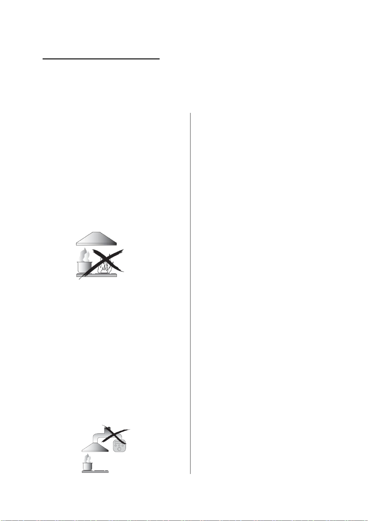
●Always put lids on pots and pans
when cooking on a gas cooker.
●When in extraction mode, air in the
room is being removed by the cooker
hood. Please make sure that proper
ventilation measures are being
observed. The cooker hood removes
odours from room but not steam.
●Cooker hood is for domestic use only.
●If the supply cord is damaged, it must
be replaced by the manufacturer, its
service agent or similarly qualified
persons in order to avoid a hazard.
●This appliance can be used by
children aged from 8 years and above
and persons with reduced physical,
sensory or mental capabilities or lack
of experience and knowledge if they
have been given supervision or
instruction concerning use of the
appliance in a safe way and
understand the hazards involved.
Children shall not play with the
appliance. Cleaning and user
maintenance shall not be made by
children without supervision.
●Warning: Before obtaining access to
terminals, all supply circuits must be
disconnected.
Always to do:
● Caution: The appliance and its
accessible parts can become hot
during operation. Be careful to avoid
touching the heating elements.
Children younger than 8 years old
should stay away unless they are
under permanent supervision.
● There shall be adequate ventilation of
the room when the cooker hood is
used at the same time as appliances
burning gas or other fuels.
●There is a fire risk if cleaning is not
carried out in accordance with the
instructions
●Regulations concerning the discharge
of air have to be fulfilled.
●Clean your appliance periodically by
following the method given in the
chapter MAINTENANCE.
●For safety reason, please use only the
same size of fixing or mounting screw
which are recommended in this
instruction manual.
●Regarding the details about the
method and frequency of cleaning,
please refer to maintenance and
cleaning section in the instruction
manual.
●Cleaning and user maintenance shall
not be made by children without
supervision.
●When the cooker hood and
appliances supplied with energy other
than electricity are simultaneously in
operation, the negative pressure in the
room must not exceed 4 Pa (4 x 10⁻⁵
bar).
●WARNING: Danger of fire: do not
store items on the cooking surfaces.
●A steam cleaner is not to be used.
●NEVER try to extinguish a fire with
water, but switch off the appliance and
then cover flame e.g. with a lid or a
fire blanket.

8
INSTALLATION (VENT OUTSIDE)
MOUNTING OF THE V-FLAP
If the cooker hood does not have an assembled V-flap 1, you should mount the half-
parts to its body.
To mount the V-flap 1 you should:
• Mount two half-parts 2 into the body 6
• a pin 3 should be top oriented;
• the axis 4 should be inserted in the holes 5 on body;
• repeat all the operations for the 2nd half-part
INSTALLATION
If you have an outlet to the outside, your cooker hood can be connected as below
picture by means of an extraction duct (enamel, aluminum, flexible pipe or inflammable
material with an interior diameter of 150mm)
1. Before installation, turn the unit off and unplug it from the outlet.

9
2. The cooker hood should not be placed at a distance of more than 200cm from an
electric hob or gas hob for the best performance. Refer to Pic 1.
3. The ceiling must can bear at least 120KGs weight, and the thickness of the ceiling
must be ≥30MM.
4. According to the cooker hood size, drill 14 holes with 8mm diameter on the ceiling
once the installation height is determined (see pic. 2),14pcs anchor bolt(or 14pcs of
ST6*40mm big flat screws+14pcs wall plugs) will be used to fix the two hanging board
on the ceiling.( see pic. 3)
5. Calculate the length of the angle iron(refer to pic 4/5),then 32pcs of M4*10 screws
and M4 nut with gasket will be used to connect the angle iron into the adjustable angle
iron bracket. (Make sure the overlap length of angle iron cannot less than 36mm)
6. Refer to pic 6,use 4 pcs ST4*8mm screws to fix the outlet onto the cooker hood
housing;

10
7. Then as pic 9 shown, choose the direction of the outlet①/②/③/④
a. Refer to Pic 7,open the decorative plate in order,and take out the filter.
b. Refer to Pic 8,unscrew and take away the 4 pcs ST4*8mm screws that on the panel
decorative strip.
c. Unscrew the 8pcs machine silk from the bottom of the cabinet housing and rotate it
by 90°/180°/270° to choose the direction of the outlet, then screw the 8 pcs machine
silk to fix the housing well;
d. Install the panel decorative strip and filter well following the opposite order of a/b
steps above,meanwhile, install the expansion pipe to the outlet(refer to pic 10).

11
7. As pic 11 shown, connect the 4 adjustable angle iron bracket with the housing by
8pcs M4*12mm machine silk screw, next refer to pic 12/13, lift up the housing, use
8pcs M4*12mm machine silk screw and M4 nut with gasket to fix the housing onto the
2 hanging board, meanwhile, pull the expansion pipe outside.(Note: The expansion
pipe must be fixed on the housing firmly.)
8. After installing the housing to the hanging board, use cross screwdriver or straight
screwdriver to adjust the screw of the angle iron bracket, direct the housing
horizontally and to the required height. Adjust method: Adjust rang of the angle iron
bracket is 0-25mm, clockwise swing the screw of the 4 angle iron bracket, slightly
move the housing upwards; meanwhile, anticlockwise swing the screw of the angle
iron bracket, slightly move the housing downwards. Use the cross screwdriver to
screw the safety screw tightly after the level position and height is suitable.(Refer to
pic 14)
HINTS FOR EXHAUST DUCT INSTALLATION
The following rules must be strictly followed to obtain optimal air extraction:
• Keep expansion pipe short and straight.
• Do not reduce the size or restrict expansion pipe.
• When using expansion pipe always install the pipe pulled taut to minimize pressure
loss.
• Failure to observe these basic instructions will reduce the performance and increase
noise levels of the cooker hood.
• Any installation work must be carried out by a qualified electrician or competent
person.
•Do not connect the ducting system of the hood to any existing ventilation system
which is being used for any other appliance ,such as warmer tube, gas tube , hot wind
tube.
•The angle of the bend of the expansion pipe should not be less than 120º; you must
direct the pipe horizontally, or, alternatively, the pipe should go up from the initial point
and should be led to an outer wall.

12
•After the installation ,make sure that the cooker hood is level to avoid grease
collection at on end.
•Ensure the expansion pipe selected for installation complies with relevant standards
and is fire retardant.
WARNING:
For safety reason, please use only the same
size of fixing or mounting screw which are
recommended in this instruction manual.
Failure to install the screws or fixing device in
accordance with these instructions may result
in electrical hazards.
Start Using Your Cooker Hood
Electronic button with LED display
After connecting power to power, the control panel will be lighted. The light
will shut off automatically after 30 seconds if without any operation.
On/Off
Switches the ventilation on and off.
Light
Switches the light on and off.
Ventilation
speed
The motor has the low speed, mid. speed and
high speed.
When the hood is working with low speed, LED
display will show 1.
Press the button, then the hood will transfer to
the mid speed for working; the LED will show 2 ,
press the speed button again , the hood will
transfer to the high speed for working
immediately. And so on..
Timer
This is a 9 minute timer. When the hood is
working, press this button to set a time for motor
operation. press the button ,LED display will be
shown 9.8.7.6 until 0, When LCD shows 0, After
30 seconds without operation; the backlight will
disappear.
Please note the Lamp is not under control of
timer.

13
Connecting the remote control
·A New remote control has to establish a new connection to the cooker hood when
used for first time. One remote control could possibly control several cooker hood at
the same time.
Connection process between remote control and cooker hood
·Press on control panel of the cooker hood, the backlight display is on, the
cooker hood is in standby mode.
·Press for 5 seconds, the indicators light begin flashing from one button to
another ,the cooker hood it in connection mode, press any bottom on remote control to
confirm the connection. The connection process finished and the remote control can
be used for speed selection, lighting and timer setting.
·If you want to connect again, you will need to clear the code that has been set up
previously.
·To clear the code, press for 5 seconds, the indicators light begin flashing from
one button to another, the cooker is in connection mode. Then, press again for 5
seconds, the previous connection code is cleared.
·When the previous code has been cleared, the cooker hood back to standby mode,
press for 5 seconds, the indicate light flashing from one button to another ,the
cooker hood is in connection mode, then, press any bottom on remote control to
confirm the connection.
Remote control
Lighting
press button once, the light is on, press again, the light is off. The lighting button
it is controlled separately and will not affect any other functions.
Turning on/ Increasing motor speed

14
1st press, Low speed
2nd press, Medium speed
3rd press High speed
Turning off/Decreasing motor speed
press the button and the motor begins shift to a lower speed and the LCD screen
display the speed level. Repeating press the button, it keep on decreasing the motor
speed to till the cooker hood turning off.
Timer
Press the button to set up the timer on/off function.
TROUBLESHOOTING
Fault
Possible Cause
Solution
Light on, but
motor does not
work
Fan switch turned off
Select a fan switch position.
Fan switch failed
Contact service center.
Motor failed
Contact service center.
Light does not
work, motor does
not work
House fuses blown
Reset/Replace fuses.
Power cord loose or
disconnected
Refit cord to power outlet.
Switch power outlet on.
Oil leakage
One way valve and the outlet
are not tightly sealed
Take down the one way valve
and seal with sealant.
Leakage from the connection
of chimney and cover
Take chimney down and seal.
Lights not
working
Broken/Faulty globes
Replace globes as per this
instruction.
Insufficient
suction
The distance between the
cooker hood and the gas top
is too far
Refit the cooker hood to the
correct distance.
The Cooker hood
inclines
The fixing screw not tight
enough
Tighten the hanging screw
and make it horizontal.

15
NOTE:
Any electrical repairs to this appliance must conform to your local, state and
federal laws.Please contact the service centre if in any doubt before
undertaking any of the above.Always disconnect the unit from the power source when
opening the unit.
MAINTENANCE AND CLEANING
Caution:
• Before maintenance or cleaning is carried out, the cooker
hood should be disconnected from the main power supply.
Ensure that the cooker hood is switched off at the wall
socket and the plug removed.
• External surfaces are susceptible to scratches and abrasions, so please follow the
cleaning instructions to ensure the best possible result is achieved without damage.
GENERAL
Cleaning and maintenance should be carried out with the appliance cold especially
when cleaning.Avoid leaving alkaline or acid substances (lemon juice, vinegar etc.) on
the surfaces.
STAINLESS STEEL
The stainless steel must be cleaned regularly (e.g.weekly) to ensure long life
expectancy.Dry with a clean soft cloth. A specialized stainless steel cleaning fluid may
be used.
NOTE:
Ensure that wiping is done along with the grain of the stainless steel to prevent any
unsightly crisscross scratching patterns from appearing.
CONTROL PANEL SURFACE
The inlay control panel can be cleaned using warm soapy water. Ensure the cloth is
clean and well wrung before cleaning. Use a dry soft cloth to remove any excess
moisture left after cleaning.
Important
Using neutral detergents and avoid using harsh cleaning chemicals, strong household
detergents or products containing abrasives,as this will affect the appliance
appearance and potentially remove any printing of artwork on the control panel and
will void manufactures warrantee.
GREASE MESH FILTERS
The mesh filters can be cleaned by hand. Soak them for about 3 minute in water with a
grease-loosening detergent then brush it gently with a soft brush. Please do not apply
too much pressure, avoid to damage it . (Leave to dry naturally out of direct sun light)
Filters should be washed separately to crockery and kitchen utensils. it is advisable
not to use rinse aid.

16
INSTALLING GREASE MESH FILTERS
• To install filters for the following four steps .
- Angle the filter into slots at the back of the hood.
- Push the button on handle of the filter.
- Release the handle once the filter fits into a resting position.
- Repeat to install all filters.
CARBON FILTER
Activated carbon filter can be used to trap odors. Normally the activated carbon filter
should be changed at three or six months according to your cooking habit. The
installation procedure of activated carbon filter is as below.
In order to install the activated carbon filter, the aluminium filter should be detached
first. Firstly open carefully the stainless steel cover, then press the lock of aluminium
filter and remove it.
NOTE:
Make sure the filter is securely locked. Otherwise, it would loosen and cause
dangerous.
When activated carbon filter attached, the suction power will be lowered.
BULB REPLACEMENT
Important :
The bulb must be replaced by the manufacturer, its
service agent or similarly qualified persons.
Always switch off the electricity supply before
carrying out any operations on the appliance. When
handling bulb, make sure it is completely cool down
before any direct contact to hands.
When handling globes hold with a cloth or gloves to
ensure perspiration does not come in contact with
the globe as this can reduce the life of the globe.

17
Change the LED light
1. Switch off the appliance and unplug it.
2. Unscrew the 2 pcs ST4*8mm big flat tapping screws on the lamp plate unit by
screwdriver.
3. Pull out the terminal, and take down the lamp plate unit.
4. Unscrew the 4 pcs ST4*8mm big flat tapping screws on the lamp plate unit and
replace the light
5. Apply reverse procedure of the above to assemble LED light and lamp plate
unit.See pic below.
• ILCOS D code for this lamp is: DSL-5-S-450
– Max wattage: 5W
– Voltage range: DC 12V
ENVIRONMENTAL PROTECTION:
This product is marked with the symbol on the selective sorting of
waste electronic equipment. This means that this product must not
be disposed of with household waste but must be supported by a
system of selective collection in accordance with Directive
2012/19/EU. It will then be recycled or dismantled to minimize
impacts on the environment, electrical and electronic products are
potentially dangerous for the environment and human health due to
the presence of hazardous substances.For more information, please
contact your local or regional authorities.
NOTE:
The following shows how to reduce total environmental impact (e.g. energy use) of the
cooking process).
(1) Install the cooker hood in a proper place where there is efficient ventilation.
(2) Clean the cooker hood regularly so as not to block the airway.
(3) Remember to switch off the cooker hood light after cooking.
(4) Remember to switch off the cooker hood after cooking.

18
INFORMATION FOR DISMANTLING
Do not dismantle the appliance in a way which is not shown in the user manual. The
appliance could not be dismantled by user. At the end of life, the appliance should
not be disposed of with household waste. Check with you Local Authority or retainer
for recycling advice.

GUARANTEE AND SERVICE CONDITIONS / BOOKING A SERVICE CALL
This certificate is issued by Falco Domestic Appliances, supplier of ALL Unbranded Falco Extractor fan models. Hereinafter referred to as ‘The Company’, to the
original purchaser only, of the product/appliances described on the certificate and shall constitute the only guarantee given in respect of this product/appliance.
The Company warrants to the original purchaser that for the period of THREE YEAR on ALL products/appliances from date of purchase the appliance should be
free from defect under normal domestic use, both in workmanship and material.
Important Notices:
This warranty shall become void and cease to be valid if the extractor fan is used for commercial purposes or on the incorrect application. This may
be subjected but not limited to; outdoors use, use in commercial kitchens, use on motor boats, use above any braai facilities, boarding school
kitchens, restaurant kitchens, coffee shops, tuck shops, commercial cookers and chips fryers. Installing and operating your domestic extractor fan
above the wrong application poses a serious fire hazard.
Noisy Extractors:
Any “noisy” extractor where the black plastic barrel/impeller fan is broken will be excluded from the guarantee and cost to replace the broken
barrel/impeller fan will be for the original purchaser/installers account. Debris such as but not limited to screws, washers, building debris are
dropped inside the motor housing and not removed during installation. This results in the barrel/Impeller fans getting damaged when the unit is
turned on for the first time. Customer/installer has to inspect the impeller/barrel fan before logging a service call for the unit being noisy, failure to
do so will result in an R 650.00 service charge. All Barrel/impeller fans are quality checked and weight balanced during the assembly line in
production. Broken barrel/impeller fans are a direct result of improper installations.
Venting outward and Ducting:
Please ensure your ducting hose (if venting outwards) does not exceed more than 2.5meters. An additional in-line extraction motor must be fitted in-
line with the ducting on all ducting exceeding 2.5 meters. To avoid losing your extraction rate it is very important to keep the length of your ducting
to a distance less than 2.5meter. The longer you’re ducting the less extraction your extractor will have unless you fit an additional in-line motor to
support in the extraction of the air. Failure to comply with this shall void the purchasers warranty until such time they correct the installation.
If not, the warranty is subject to the following conditions:
1. Repair or replacement of any part of this product/appliance, found by The Company to be defective, shall be at the cost of The Company. The
Company reserves the right to affect such service through any Service Division authorised by The Company to carry out service on The Company’s
products/appliances. The cost of the service shall be borne by The Company in full, providing that the product/appliance is located no further than
50km from an authorised service agent.
Where the product/appliance is located beyond the 50km radius, the purchaser shall be liable for the standard travelling charges, as determined by
The Company or alternatively, The Company reserves the right to ask the purchaser to deliver any faulty product/appliance to the dealer from which it
was bought or nearest service agent, for repairs. After the said repair has been completed, the original purchaser is again responsible for the
collection and transportation of said product/appliance.
2. All lamps, halogen lamps, globes, aluminium filters, charcoal filters are excluded from these warranties. Abuse, misuse in conflict with the
operating instructions, connection to incorrect voltages (generators, solar panels, wind turbines without the additional and compulsory addition of pure
sine wave invertors), shall release The Company from all its obligations under warranty. It is an express condition of these warranties that the
purchaser takes due care and attention in the use and maintenance of the product/appliance.
3. Any physical damage to the product/appliance that occurred prior to delivery/receipt of the product/appliance will only be included in this warranty
provided that it is reported, together with the proof of purchase within 48 hours thereof. Any part on any of the abovementioned products/appliances
will be excluded from this warranty, should findings indicate that the parts are damaged or malfunctioning because of any form of physical damage.
4. This warranty shall become void and cease to be valid if the product/appliance is dismantled by, or any repairs to the product/appliance are affected
by any person not authorised by The Company, or if replacement parts not approved by The Company are used in any product/appliance, or if the
serial number of the product/appliance is removed.
5. These warranties shall not apply if the product/appliance is purchased or used beyond the borders of the Republic of South Africa (Swaziland,
Lesotho, Namibia, Botswana and Zimbabwe).
6. The Company shall not be responsible for damages resulting from fire, floods, civil disturbances or any Act of God. The Company shall not, in terms
of these warranties be responsible, nor held liable for any consequential loss or damage of any kind caused by or due to the failure or malfunctioning
of the appliance/product.
7. The Company shall not be held responsible for transportation/other costs other than those incurred within the provisions of Point 1 of this Certificate.
8. Where service is requested under warranty and no fault or any defect is found by the Company service agents, all costs incurred will be for the
purchaser’s account.
9. This certificate together with the purchaser’s proof of purchase (Invoice from Dealer) will serve as proof of purchase. For warranty purposes, it will be
essential to produce this Certificate with the Invoice. Failure to do so will render the purchaser liable for service costs.
10. The Company will not exchange any faulty product/appliance still under warranty EXCEPT if the appointed service agent inspects and confirms with
valid proof that the appliance is irreparable.
11. Where the purchaser lives in an outlying area (farms/ remote locations) where appointed Service Agents are scarce or non-existent, The Company
reserves the right to request such a purchaser to transport the unit to and from the nearest appointed Service Agent for repairs.
12. This warranty shall become void and cease to be valid if the product is installed at the incorrect height. Please refer to your manual.
13. This warranty shall become void and cease to be valid if the incorrect size Extractor Fan is installed above any electrical or gas hob. Example of such
an installation is installing a 600mm Extractor above a 900mm gas or electrical hob.
14. This warranty does not cover rodent or insect infestation.
15. Repairs and parts covered by the Company includes: the motor, the PCB, the power and light switch, the capacitor, the motor fan blade an
transformer.
Booking a Service call
16. Extractor Fan Warranty calls: Lategan & Van Biljoens Appliance Spares (LVB), 636 Frederika Street, Gezina, Pretoria, PO Box 23151, Gezina,
0031, Pretoria . Warranty Tel:(012) 330-0287 extension 207or 301; Fax: 086-684-2247; email: [email protected].za
Visit www.falco.co.za and complete the online service form and submit with a copy of your proof of purchase. Alternatively print the service
form and return it with a copy of your proof of purchase to admin@lvb.co.za or by fax on 086-684-2247 Please include your email address on the
service form, all booking notifications are sent out via email correspondence.
Any service-related queries should be directed directly to (LVB). The appointed call centre, Lategan & Van Biljoens Appliance spares (LVB), will allocate the
service call under the warranty procedure to one of their closest service agents in the purchaser’s area. No service call will be considered under the warranties
if no proof of purchase can be presented
Happyor Unhappylets us know: [email protected].za Tel: 011 454 6423/4314/6146
Table of contents
Other FAL Ventilation Hood manuals
Popular Ventilation Hood manuals by other brands

Swegon
Swegon CASA Smart Blues Instructions for use

Columbus
Columbus SX 344 operating manual

Gorenje Plus
Gorenje Plus GHV62X Instruction on mounting and use

Asko
Asko CC4840S operating instructions

Hoover
Hoover HHT6300/2X/1 instruction manual

Franke
Franke FTU 3807 W Installation instructions use and care guide