FAL AR-60-701 User manual

INSTALLATION AND USER’S MANUAL
Model:
AR-60-701, AR-90-701
AR-60-736, AR-90-736
AR-60-706RGB, AR-90-706RGB

Warranty and service certificate:
This certificate is issued by Falco Domestic Appliances, supplier of ALL Unbranded Falco Extractor fan
models. Hereinafter referred to as ‘The Company’, to the original purchaser only, of the product/appliances
described on the certificate and shall constitute the only warranty given in respect of this product/appliance.
The Company warrants to the original purchaser that for the period of THREE YEAR on ALL extractor fans
from date of purchase the appliance should be free from defect under normal domestic use, both in
workmanship and material.
Important Notice:
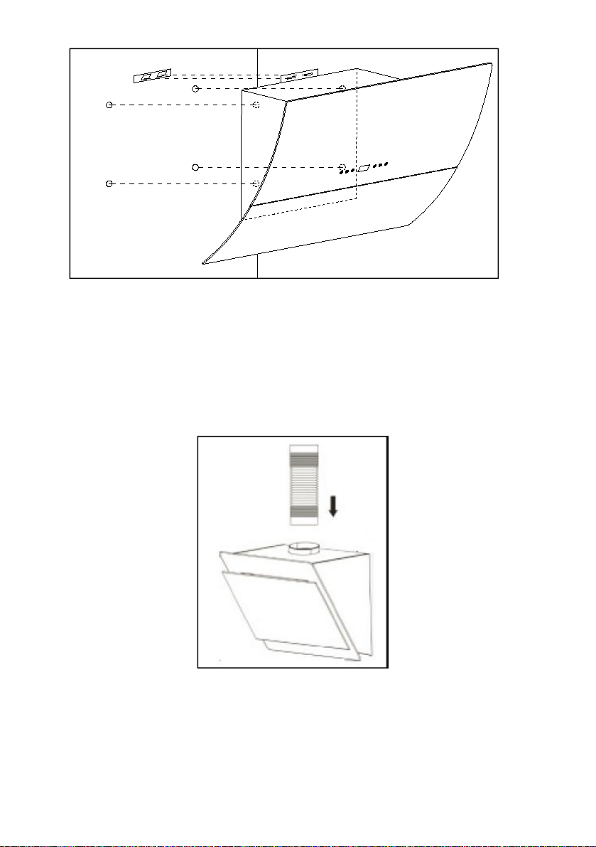
Please DO NOT remove the warning label on the motor housing until the installation is finished. Debris
dropped inside the motor housing during installation causes the motor fanstobreakwhentheunitis
turned on resulting in a very loud and noisy extractor. All fans are tested on the assembly line before
packaging.
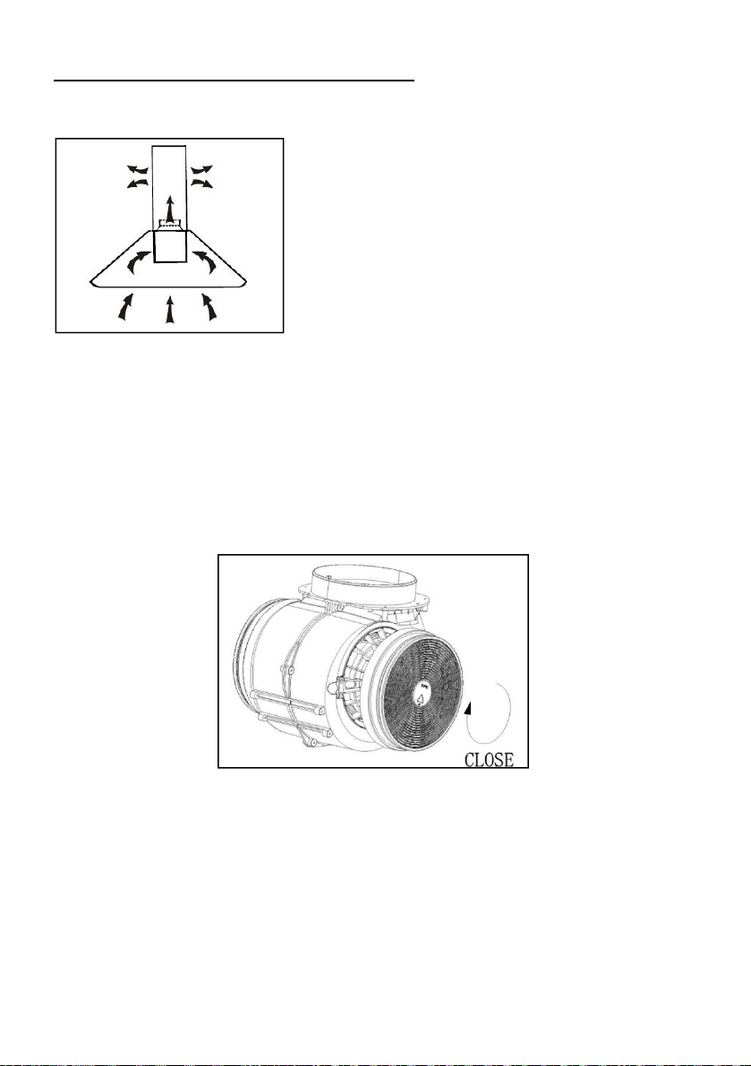
Venting Outward and Ducting: Please ensure your ducting hose (if venting outwards) does not exceed
more than 2.5meters. An additional in-line extraction motor must be fitted in-line with the ducting on all
ducting exceeding 2.5 meters. To avoid losing your extraction rate it is veryimportanttokeepthelength
of your ducting to a distance less than 2.5meter. The longer you’re ducting the less extraction your
extractor will have unless you fit an additional in-line motor to support in the extraction of the air.
Failure to comply with this shall void the purchaser’s warranty until such time they correct the installation.
If not, the warranty is subject to the following conditions:
1. Repair or replacement of any part of this product/appliance, found by The Company to be
defective, shall be at the cost of The Company. The Company reserves the right to affect such
service through any Service Division authorised by The Company to carry outserviceonThe
Company’s products/appliances. The cost of the service shall be borne by The Company in full,
providing that the product/appliance is located no further than 50km from an authorised service
agent.
Where the product/appliance is located beyond the 50km radius, the purchaser shall be liable for
the standard travelling charges, as determined by The Company or alternatively, The Company
reserves the right to ask the purchaser to deliver any faulty product/appliance to the dealer from
which it was bought or nearest service agent, for repairs. After the said repair has been
completed, the original purchaser is again responsible for the collection and transportation of
said product/appliance.
2. Where the purchaser lives in an outlying area (farms/ remote locations) where appointed
Service Agents are limited or non-existent, The Company reserves the right to request such a
purchaser to transport the unit to and from the nearest appointed Service Agent for repairs.
3. The Company shall not be held responsible for transportation/other costs other than those
incurred within the provisions of Clause 1 and 2 of this Certificate.
4. All lamps,halogen lamps,globes,LED lights,aluminium filters,charcoal filters and
extractor glass panels, are excluded from these warranties. Abuse, misuse in conflict with the
operating instructionsor connection to incorrect voltages (generators, solar panels, wind turbines
without the additional and compulsory addition of pure sine wave invertors), shall release The
Company from all its obligations under warranty. It is an express condition of these warranties
that the purchaser takes due care and attention in the installation, use and maintenance of the
product/appliance.
5. Any physical damage to the product/appliance that occurred prior to delivery/receipt of the
product/appliance will only be included in this warranty provided that it is reported, together with
the proof of purchase within 48 hours thereof. Any part on any of the abovementioned
products/appliances will be excluded from this warranty, should findings indicate that the parts
are damaged or malfunctioning because of any form of physical damage.
6. This warranty shall become void and cease to be valid if the product/appliance is dismantled by,
2

___
or any repairs to the product/appliance are affected by any person not authorised by The
Company, or if replacement parts not approved by The Company are used in any
product/appliance, or if the serial number of the product/appliance is removed.
7. These warranties shall not apply if the product/appliance is purchased or used beyond the
borders of the Republic of South Africa (Swaziland, Lesotho, Namibia, Botswana and
Zimbabwe).
8. The Company shall not be responsible for damages resulting from fire, floods, civil disturbances
or any Act of God. The Company shall not, in terms of these warranties be responsible, nor held
liable for any consequential loss or damage of any kind caused by or due to the failure or
malfunctioning of the appliance/product.
9. Where service is requested under warranty and no fault or any defect is foundbythe
Company service agents, all costs incurred will be for the purchaser’s account.
10. This certificate together with the purchaser’s proof of purchase (Invoice from Dealer) will serve as
proof of purchase. For warranty purposes, it will be essential to produce this Certificate with the
Invoice. Failure to do so will render the purchaser liable for service costs.
11. The Company will not exchange any faulty product/appliance still under warranty EXCEPT if the
appointed service agent inspects and confirms with valid proof that the appliance is irrepairable.
12. This warranty shall become void and cease to be valid if the product is installed at the incorrect
height. Please refer to your manual.
13. This warranty shall become void and cease to be valid if the incorrect size Extractor Fan is
installed above any electrical or gas hob. Example of such an installation is installing a 600mm
Extractor above a 900mm gas or electrical hob.
14. This warranty does not cover rodent or insect infestation.
15. Repairs and parts covered by the Company includes: the motor, the PCB, the power and
light switch, the capacitor, the motor fan blade and transformer.
16. This warranty shall become void and cease to be valid if the extractor fan is used for commercial
purposes or on the incorrect application. This may be subjected but not limited to; outdoors use,
use in commercial kitchens, use on motor boats, use above any braai facilities, boarding school
kitchens, restaurant kitchens, coffee shops, tuck shops, commercial cookers and chips fryers.
Installing and operating your domestic extractor fan above the wrong application poses a serious
fire hazard.
Appointed call centre:
Lategan & Van Biljoens New Appliances & Spares (LVB)
636 Frederika Street, Gezina, Pretoria, PO Box 23151, Gezina, 0031, Pretoria
Service call centre: Tel: (012) 330-0287 ext 6; Whatsapp:074-206-5132
Alternatively book a service call online using the following link: www.falco.co.za/service.
Any service-related queries should be directed directly to the dealer (store) where the unit was
purchased. Alternatively, the purchaser can contact the appointed call centre on the details provided
above. The appointed call centre, Lategan & Van Biljoens New Appliances & spares (LVB), will allocate
the service call under the warranty procedure to one of their closest service agents in the purchaser’s
area. No service call will be considered under the warranties if no proof of purchase can be presented.
3

Table of Contents
INTRODUCTION.......................................................................................................5
SAFETY PRECAUTIONS............................................................................................ 5
INSTALLATION (EXTERNAL DUCTING)....................................................................6
INSTALLATION (AIR RECIRCULATION)..................................................................10
OPERATION (AR-60-701 / AR-90-701)..................................................................11
OPERATION (AR-60-736 / AR-90-736)..................................................................15
OPERATION (AR-60-706RGB / AR-90-706RGB)....................................................18
MAINTENANCE......................................................................................................22
TROUBLESHOOTING............................................................................................. 24
FREQUENTLY ASKED QUESTIONS.........................................................................25
ENVIRONMENTAL PROTECTION...........................................................................28
4

INTRODUCTION
This instruction manual is designed to provide you with all the required
instructions related to the installation, use and maintenance of the
appliance.
In order to operate the unit correctly and safety, please read this
instruction manual carefully before installation and usage.
This extractor makes use of high quality materials and is made with a
streamlined design.
It is equipped with large electric motor with a centrifugal fan, which
provides strong suction power, low noise operation.
SAFETY PRECAUTIONS
Never let children operate the extractor
The extractor is designed for domestic use and is not suitable for
use with barbeques or any commercial application.
The extractor and its filters should be regularly cleaned, to avoid
any fire hazards due to oil build up in and around the extractor.
If the supply cord is damaged it must be replaced by the
manufacturer or qualified service agent to avoid electrical hazards.
Only connect this unit to a properly earthed electrical outlet. If in
doubt seek advice from a qualified electrician – Failure to follow
this could result in death or electrical fire.
If ducting the air outside, it must not be discharged into a flue that
is being used to vent out exhaust fumes from appliances burning
gas or other fuels.
This appliance can be used by children above the age of 8 if they
have been given supervision and/or instruction concerning the
safe use of the appliance.
CAUTION: Some parts of the extractor may be become hot during
use with a gas cooker.
5

INSTALLATION (EXTERNAL DUCTING)
1. If you plan on ducting the air to the outside, your extractor can be
connected as per the picture below to a ducting pipe with an internal
diameter of 150mm.
2. The extractor should be mounted at the following distances above the
counter top:
Above a gas hob or cooker – 75cm, but not exceeding 75cm.
Above an electrical hob or cooker – 65cm, but not exceeding
75cm.
6

3. Drill 3 x 8mm holes to accommodate the mounting bracket. Screw
and tighten the bracket onto the wall with the provided screws and
plugs.
4. Lift up the extractor and hang it on the now mounted wall bracket.
Certain models will require that additional screws be used to further
secure the extractor to the wall, this will entail opening up the
extractor’s front flap, removing the aluminum filter/s and then securing
it to the wall using the pre-drilled holes at the back of the unit.
Cooker hood
Holes on wall
Screw Plug
Wall Bracket
Screw (4mm x
30mm)
Wall bracket
7

5. Fix the provided ducting pipe to the air outlet of the extractor as in the
picture below:
8

Fitting the Chimneys to the Extractor:
Slide the top chimney piece (this is the one with the vents holes cut
into the sides) into the bottom section (this one is solid, with no vent
holes).
1. Adjust the total chimney length, by sliding the two chimney sections to
the required length. Once the required length is determined, fix the
bracket with the provided screws as shown in the picture below:
2. Drill 2 x 8mm holes to accommodate the Plate II. Screw and tighten
the plate II onto the wall with the two screws provided.
Fit the chimney section on top of the extractor and fix it in place with
the screws.
Upper Chimney
Bottom Chimney
Plug
Plate II
Screw (4mm x 8mm)
Screw (4mm x
9

INSTALLATION (AIR RECIRCULATION)
If ducting the air to the outside with the ducting pipe is not possible, then
the ducting pipe can be discarded.
The installation of the extractor is the same as previously shown, the only
difference is that carbon filters (provided) assist in trapping/capturing
odours.
10

Attach the carbon filters to the motor of the extractor and turn it in a
clockwise direction.
Ensure that the carbon filters are securely locked in place.
Please note that once the filters are fitted to the extractor, the
suction power of the unit will decrease somewhat.
OPERATION
Touch control for models:
AR-60-701, AR-90-701
Touch control panel
Remote Control
Before using the remote control, please remove the battery’s plastic film.
11

Standby Mode
After initial plug in, the flashes slowly, this means the unit is in
standby, mode.
Switching the unit on and off
In standby mode, press the button, the display will illuminate, and
the extractor will switch on.
The unit is now in WORKING MODE.
If it’s the initial startup, the motor will be on the low speed and the
downlights will remain off. If the unit was used before, it will revert
back to its last operation setting.
(The above is the same whether the unit is switched on using the
remote control or the control panel on the extractor).
While the unit is in WORKING MODE, and the power button is
pressed , the motor will switch off, but the downlights status
will not change.
While the unit is in WORKING MODE, and the power button is
pressed for 3 seconds, the motor and downlights will switch
off, and the unit will go into STANDBY MODE.
(If the power button is briefly pressed on the remote control,
the above will occur).
12

Changing the fan speed
If the fan speed button is pressed on the extractor or the remote,
the extractor’s motor will cycle through fan speeds Low / Medium /
High.
This button will not power-off the unit.
Switching the downlights on and off
Short pressing the light button will switch on/off the extractor’s
downlights.
Long pressing the light button
1. Will turn off the cleaning symbol and reset the total working time of
the extractor – When the cleaning symbol is displayed.
2. Will show the current total working time of the extractor – When the
cleaning symbol is not displayed.
Clock setting
While the extractor motor is running, press and hold + for 1
second, the following will flash “88:88” on the display, the unit is now in
CLOCK SETTING MODE.
Press to select hours or minutes.
Press to decrease the values.
Press to increase the values.
13

To save the time press and hold the following for 1 second, + ,
or simply refrain from pressing any buttons for 5 seconds to
automatically save the setting.
Timer setting
When the motor is working, press and hold + for 1 second.
The display will show the following “00:00” while flashing, the unit is
now in the TIMER MODE.
Press to 15 minutes.
Press to decrease 1 minute.
Press to increase 1 minute.
To save the setting press and hold + for 1 second, or simply
refrain from pressing any buttons for 5 seconds to automatically save
the setting.
When the time “runs out” both the motor and the downlights will switch
off and the unit will go into STANDBY MODE.
14

LCD DISPLAY
1. Fan symbol, will turn on when the fan is working
2. Time display
3. Timer
4. Light
5. Fan speed
6. Alarm symbol
7. Cleaning symbol, appears when total working time reaches 14
hours or at the initial start-up.
OPERATION
Touch control for models:
AR-60-736, AR-90-736
15

After the plugging the extractor into the power supply, the unit will
automatically go into STANDBY MODE
SPEED INCREASE BUTTON
Used to switch on the extractor and to increase the fan speed.
SPEED DECREASE BUTTON
Used to switch off the extractor and to decrease the fan speed.
TIMER BUTTON
While the unit is in STANDBY MODE press the timer button to enter
CLOCK SETTING MODE.
The hour display will flash, press and to adjust the hours.
Press to change to minutes.
The minutes display will flash, use and to adjust the minutes.
Press to save the setting or wait 10 seconds to save
automatically.
While the unit is in WORKING MODE, short press the button to
cycle through one of the following timer settings: OFF – 15 min – 30
min – 45 min – 60min – OFF.
Alternatively, pressing or can also be used.
16

Quick Timer:
Press and hold for 1 second, the digital display will flash and
countdown from 5 minutes, after which the motor and downlights will
switch off.
LIGHT BUTTON
Short press the light button to switch the downlights on and off.
Long pressing the light button
1. Will turn off the cleaning symbol and reset the total working time of
the extractor – When the cleaning symbol is displayed.
2. Will show the current total working time of the extractor – When the
cleaning symbol is not displayed.
LCD DISPLAY
1. Fan symbol, will turn on when the fan is working
2. Countdown timer display
3. Timer
4. Light
5. Fan speed
6. Alarm symbol
17

7. Cleaning symbol, appears when total working time reaches 14
hours or at the initial start-up.
OPERATION
Touch control for models:
AR-60-706RGB, AR-90-706RGB
After the plugging the extractor into the power supply, the unit will
automatically go into STANDBY MODE
SPEED INCREASE BUTTON
Used to switch on the extractor and to increase the fan speed.
SPEED DECREASE BUTTON
Used to switch off the extractor and to decrease the fan speed.
Controls downlights and Mood lighting functionality
18

P1: Lowest speed
P2: Middle speed
P3: High speed
TIMER BUTTON
While the unit is in STANDBY MODE press the timer button to enter
TIMER SETTING MODE.
The minutes display will flash, use and to adjust the minutes.
Press to save the setting or wait 10 seconds to save
automatically.
While the unit is in WORKING MODE, short press the button to
cycle through one of the following timer settings: OFF – 15 min – 30
min – 45 min – 60min – OFF.
Alternatively, pressing or can also be used.
Quick Timer:
Press and hold for 1 second, the digital display will flash and
countdown from 5 minutes, after which the motor and downlights will
switch off.
DOWNLIGHTS & MOOD LIGHTING BUTTON
19

1. Short pressing (about 1 second) the light button will turn on the
downlights of the extractor. To switch off the lights, repeat the
above.
2. Long pressing (5 seconds) the light button
a. Will turn off the cleaning symbol and reset the total
working time of the extractor – When the cleaning symbol
is displayed.
b. Will show the current total working time of the extractor –
When the cleaning symbol is not displayed.
3. Switching on the Mood Lighting – Long press (3 – 5 seconds) the
light button . This will enter the Mood Lighting Setting
Mode.
One of the following will displayed:
A0: Mood Lighting standby mode/ off
A1: RED
A2: GREEN
A3: BLUE
A4: WHITE
A5: MIX COLOR =A1+A2+A3
By immediately pressing the button again will cycle through the
different colours (as above).
If no further selection is made promptly, the unit will automatically
save and exit the mood lighting settings.
To re-enter, simply long press the again.
20
This manual suits for next models
5
Table of contents
Other FAL Ventilation Hood manuals
Popular Ventilation Hood manuals by other brands

FALMEC
FALMEC MILANO+ installation manual

Gurari
Gurari GCH I 385 PRIME Manual for installation and use

Lamona
Lamona HJA2480-1 User's installation guide

Beko
Beko HB60PX User instructions

montpellier
montpellier MHD650BK Installation and operating instructions

Broan
Broan Quiet Hood QT20000 SERIES installation instructions