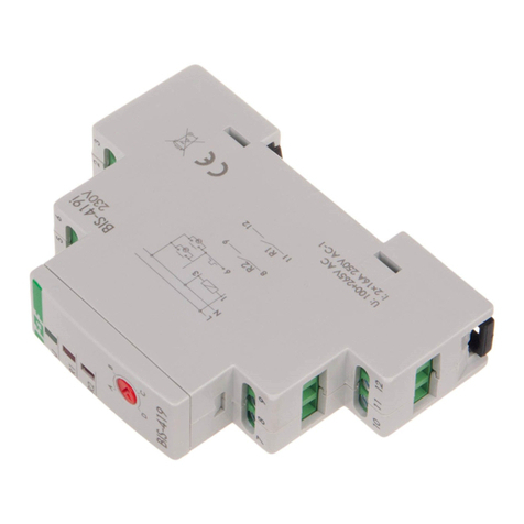
F&F PCS-533 User manual

ul. Konstantynowska 79/81
Programmable time relay
PCS-533
User manual
v. 1.0.1

home and industrial automation
PCS533 programmable time relay –User manual v. 1.0.1 2
Information concerning the safe use of the relay is marked with symbols. All information and recommendations
bearing these symbols should be strictly obeyed.
Risk of electric shock.
Potentially dangerous situation that could lead to a danger for the operating
personnel or damage to the relay.
Information concerning the design, operation and maintenance of the time relay.
Important information, valuable tip.
Practical advice, problem solution.
An example of use or operation.

home and industrial automation
PCS533 programmable time relay –User manual v. 1.0.1 3
Table of contents
Introduction..................................................................................................................................................................5
Installation....................................................................................................................................................................5
Description of terminals ...........................................................................................................................................5
Specification .............................................................................................................................................................5
Connection schemes.................................................................................................................................................6
Indications ................................................................................................................................................................8
PCS33 Configurator.....................................................................................................................................................10
Welcome screen .....................................................................................................................................................10
Main menu..............................................................................................................................................................11
Program editor .......................................................................................................................................................12
Edit program list .................................................................................................................................................15
Scroll program list...............................................................................................................................................15
Edit entries..........................................................................................................................................................16
Delete entries .....................................................................................................................................................17
Change the order of entries ...............................................................................................................................17
Command list..........................................................................................................................................................18
Reset ...................................................................................................................................................................18
Stop.....................................................................................................................................................................19
Pause...................................................................................................................................................................21
Return to.............................................................................................................................................................22
Output.................................................................................................................................................................23
Input A ................................................................................................................................................................25
Input B ................................................................................................................................................................25
Input A –special function...................................................................................................................................27
Input B –special function ...................................................................................................................................27
Templates ...............................................................................................................................................................29
Template list ...........................................................................................................................................................30
01) Delayed switching on....................................................................................................................................30
02) Delayed switching off ...................................................................................................................................31
03) Generate a single pulse with rising edge......................................................................................................32
04) Generate a single pulse with trailing edge...................................................................................................33
05) Switch-off delay with support function........................................................................................................35
06) Generate a single pulse after a preset time .................................................................................................36
07) Cyclic delayed switching on..........................................................................................................................37
home and industrial automation
PCS533 programmable time relay –User manual v. 1.0.1 4
08) Cyclic delayed switching off..........................................................................................................................38
09) Switching on of the contact for the time t1 with the button pressed and for the time t2 with the button
released ..............................................................................................................................................................39
10) Generate a preset number of pulses............................................................................................................40
11) Generate pulses for a preset period of time................................................................................................41
History of changes ......................................................................................................................................................43
Warranty.....................................................................................................................................................................44

home and industrial automation
PCS533 programmable time relay –User manual v. 1.0.1 5
Introduction
PCS533 is a programmable time relay that allows the implementation of simple programs for controlling the
output relay as a function of time and in conjunction with signals directed to control inputs A and B. The
operation mode of the controller is prepared via graphical application running on the Android phone. NFC
interface built-in the phone is used to transfer the program (*).
Installation
Description of terminals
1-3) Power supply - 12-265V AC/DC
4) Control input A
6) Control input B
10) Relay output –contact normally closed (NC)
11) Relay output –common contact (COM)
12) Relay output –contact normally open (NO)
Fig. 1) Description of terminals
Please note: No galvanic isolation between the power supply (terminals 1 - 3) and the control
inputs (terminals 4 and 6). In case of a mains power this means that a dangerous
potential can emerge on the terminals 4 and 6.
Specification
Power supply: 12 –265 V AC/DC
Control inputs
oNumber of inputs: 2
oControl voltage: 12 –265 V AC/DC
oTriggered with:
level L or N for AC power supply
level + for DC power supply
oInput circuit triggering current < 1 mA
Output

home and industrial automation
PCS533 programmable time relay –User manual v. 1.0.1 6
oSingle relay with NO/NC contact
oAcceptable load
16 A for 250 V AC voltage in load class AC-1
16 A for 24 V DC voltage
1 A for >24 V DC voltage
Relay type: Freely programmable
Number of program steps: 200
Timers: from 0.1 to 24h
Controller state indication: 2 x LED
Power consumption:
o0.8 W with relay on
o0.4 W in standby mode
Operating temperature: -25 … + 50 degrees
Thermal protection: 70 degrees
Terminal: Screw terminals, max. 2.5 mm2
Installation: on DIN rail. Size 1S
Ingress protection: IP20
Connection schemes
Fig. 2) Alternating voltage power supply (control with level L)

home and industrial automation
PCS533 programmable time relay –User manual v. 1.0.1 7
Fig. 3) Direct voltage power supply (control with level +)
Fig. 4) Separated power supply circuit/control and receiver

home and industrial automation
PCS533 programmable time relay –User manual v. 1.0.1 8
Indications
The PCS533 relay is equipped with two signaling LEDs. During normal operation the green LED indicates the
presence of power supply voltage. The red LED indicates the switching on of the relay. Flashing of one or both
controls indicates the emergency situation. The list of possible errors is shown in the following table.
No program
Flashing green LED and red LED off indicates that there is no proper program to
execute saved in the memory of the controller.
Please note: Due to the way the program is transferred from phone to
controller, it may happen that the whole program will not be properly
copied to the memory of the controller. In this case, when the NFC
connection is broken, the controller tries to load new program and in
case of an error it indicates it by flashing green LED. Similar verifying
procedure is performed when the controller activates.
Disruption of the timer signal
In case of a strong electromagnetic interference the operation of the quartz
generator that is used for measuring the time may be disrupted. In that case the
controller will switch to the secondary clock of lesser accuracy. In that situation,
move the controller away from the source of interference.
Disruption of the memory readout
Strong electromagnetic interference may also lead to disruption of
communication with EEPROM memory that stores the program configuration.
The relay is equipped with procedures for restoring the communication with
memory, but if such errors occur it is recommended to move the relay away
from the source of interference.
Exceeding the temperature
Alternate flashing controls indicate the maximum temperature inside the
module. Until the temperature does not drop to a safe value, the relay will be
switched off and the program execution stopped.
Temperature alarm may occur in the following cases:
1. Too high load of the relay contacts. In this case reduce
the load, for example through the use of an additional
contactor through which the load will be switched on.
2. Too high ambient temperature. In this case improve
ventilation in the distribution box or increase spacing
between modules to improve heat dissipation.
3. Too high power supply voltage (above 265 V)
4. Improperly tightened terminals of the controller power
supply (1-3) or load (10-12)
General error
General error of the controller is signaled by the simultaneous flashing of both
control lights. It indicates the faulty operation of the controller or erroneous
entry in the configuration memory.

home and industrial automation
PCS533 programmable time relay –User manual v. 1.0.1 9
The most common cause of a general error is erroneous entries
in the controller program memory. Usually they appear in case of
an incorrect transfer of the program from the phone to the
controller (for example caused by the communication break
during data copying).
In the case of a general error in each case again copy the program from the
phone to the controller.

home and industrial automation
PCS533 programmable time relay –User manual v. 1.0.1 10
PCS33 Configurator
All operations related to the preparation of the program, copying from/to the controller and managing the
programs is realized through the PCS533 Configurator application. This application is designed for phones and
tablets running on Android (version at least 4.0). In addition, to communicate with the controller the phone or
tablet must be equipped with near field communication (NFC) module. The PCS533 Configurator app can be
downloaded free of charge via the Google Play store.
Google Play store performs initial verification and blocks the ability to install the app on devices
that do not meet the application requirements (for example lack of NFC module or unsupported
version of Android). In this case, the attempt to search the app in the store will fail and the
message about the lack of searched application will be displayed.
Welcome screen
After starting the PCS533 Configurator, a window is displayed that allows you to read the program from the PCS
controller. (
Fig. 5
Fig. 5) Welcome screen
According to the instructions on the screen, when you bring the phone
closer to the PCS533 controller, the connection will be made automatically
and the program from the controller memory will be copied to the
application.

home and industrial automation
PCS533 programmable time relay –User manual v. 1.0.1 11
NFC (Near Field Communication) is used for connecting the controller and the phone and has a
small operational range. Therefore, due to the small size of the antenna in the controller and
equally small NFC antennas in phones, difficulties in the connection making may occur. In this
case you need to experimentally locate the antenna in the phone by slowly moving the phone
over the front elevation of the controller until the connection is made (indicated by displaying
the download progress bar, among other things).
In case the NFC module in the phone is disabled when the application starts, the appropriate message will be
displayed on the screen (Fig. 6) that redirects to the phone settings where you can enable the NFC module.
Fig. 6) Message about disabled NFC module
Main menu
Main menu is opened by clicking on the icon located in the upper left corner of the application (Fig. 7).
Fig. 7) Opening main menu
The look of the main menu is shown in Fig. 8 and it is composed of the following commands:
Continue editing –Return to the edition of the current program. This command does not appear if there
is no program in the memory of the configurator.
New configuration –create new, empty program file.
Templates –a list of pre-defined operating programs. For use as a ready solutions or as a base to create
your own program.
Load from file –read the previously created program from the phone memory.
Restore –the ability to run any program saved in the memory of the controller.
Main
menu

home and industrial automation
PCS533 programmable time relay –User manual v. 1.0.1 12
Information –a brief description of the application.
The details of each command are described below.
Fig. 8) Main menu
Program editor
Program editor is the main view of the PCS533 Configurator app and it is designed for the creating and editing of
the program of the controller operation.
If any program is loaded to the application at the opening of the editor window, a message will be displayed with a
question what to do with the previous entry (Continue or start over?
Start over - Continue
Fig. 9
Previous entry was interrupted.
Continue or start over?
Start over - Continue
Fig. 9) Configuration override
Selecting Start over option removes the previous entry and opens new configuration. Continue
option stops the execution of the command and leaves the previous configuration.
Example screen of the program editor is shown in Fig. 10. It consists of the following elements:
Header at the top of the screen If the program is linked with the particular controller, the DEV parameter
displays the identifier of the device type (PCS533) and the ID parameter - the unique identification
number of the controller.
By default the identifier of the clock is presented as a serial number of the controller. It is also
possible to give the device other name. This is done using the button with a pencil symbol that
is located on the right side of the header. After entering your own name, it will appear
whenever you connect with a given controller.
Workspace in the middle part of the screen with a list of commands to perform.

home and industrial automation
PCS533 programmable time relay –User manual v. 1.0.1 13
Fig. 10) Program window
Bar with the function keys on the bottom of the screen:
oSave to file. This command allows you to save the current list of programs to a file. When you
press the button, a dialog box appears that allows you to enter a file name.
Fig. 11) Saving program to a file
The file saved in this way will be available from the Load from file command that is located in the
main menu of the application.
Please note: The application does not verify whether a file with the entered name
already exists. If you will use the same name, the new configuration will
be overwritten in place of the previous one without displaying any
additional warning.

home and industrial automation
PCS533 programmable time relay –User manual v. 1.0.1 14
oSave to PCS –a command to copy the current program to the PCS533 controllers. When you
press the button, a message box will appear asking you to bring the phone closer to the device in
order to save data.
Fig. 12) Save to PCS
Data copying will start automatically once the phone and controller are connected. When the
copy is done, a message box will appear with information about correct or invalid saving of the
program. If the copying process was correct, you can program other controllers without taking
any action in the application - you just need to bring the phone closer to the next controller. To
stop further entries, press the Cancel button displayed on the screen. The new program in the
controller will begin to execute immediately after the connection between phone and controller is
terminated.
If the controllers are in close proximity to each other, the transmission may be
interfered, for example part of the program may be copied to one device, and
part to the other. In such situation it is recommended to spread controllers
apart for the time of programming or for example draw out the programmed
controller higher. The controllers may also be programmed with the power
supply voltage off, so the power failure does not prevent the interference in
such cases.
oAdd command - a command that displays a window with a list of commands that can be added to
the program (Fig. 13). A detailed description of those commands and their parameters is
presented later in this manual.

home and industrial automation
PCS533 programmable time relay –User manual v. 1.0.1 15
Fig. 13) Adding/editing command
Edit program list
Program of the PCS533 controller can contain up to 200 steps executed according to the order of appearance on
the list.
Scroll program list
To scroll the list of the programs press the right side of the program list (Fig. 14) and then move the view to the
previous or next program steps by moving the list up-down.
Fig. 14) Scroll program list

home and industrial automation
PCS533 programmable time relay –User manual v. 1.0.1 16
Edit entries
To enter the edit mode of the selected step, briefly click the command entry. You will then see the command edit
window - examples (depending on the edited command) are shown in Fig. 15.
Fig. 15) Command edit window
Edit window consists of three main parts. The upper one contains the name of the command and icon symbolizing
it - in examples from Fig. 15 they are respectively: Pause, Return to and Input A. On the right side of the name of
the command is located the i button - it displays a window with detailed information concerning the selected
command (the example for the Return to command is shown in Fig. 16).
Information
A jump to a preset program step is carried out. We assume that the jump can be
done only to the existing step. The Counter parameter determines how many
times the jump will be done. If the Counter=0, the number of returns is
unlimited. If the Counter>0 then the program will execute a preset number of
steps. Please note: the Return to commands cannot be in loop.
Fig. 16) Information for Return to command

home and industrial automation
PCS533 programmable time relay –User manual v. 1.0.1 17
Delete entries
To delete a selected program entry, press and hold it and then move it to the left or right.
Fig. 17) Deleting program entry
.
Please note: When you remove program entries, you should pay close attention and remember
that it may change the way the program operates. This is particularly true for the jump
commands which may be placed in the further part of the program. As a result of the removal of
the step, the jump will not return to the assumed point of the program.
After removing the command at the bottom of the screen the „Restore removal” message will be
displayed (Fig. 18). It allows you to recover accidentally erased command.
Fig. 18) Restoring deleted command
Change the order of entries
The order of the commands on the list determines the order of their implementation by the controller. By holding
down the symbol located on the left side of the entry you can move the command to the new position in the
program.
Please note: Changing the order of entries may result in undesirable behavior of the program -
this is particularly true for the jump instructions that after such change will not return to the
assumed point of the program.

home and industrial automation
PCS533 programmable time relay –User manual v. 1.0.1 18
Command list
Reset
The Reset command:
aborts the current program;
switches off the relay;
resets the internal timers and counters of the program loop;
deletes the settings of the special inputs;
causes the return to the first step of the program and starts the execution of the program from the
beginning.
The execution of the Reset command may be delayed for the time specified with parameter Select time t in range
from 0.0 (immediate execution of command) to 24 hours in increments of 0.1 s. Countdown to execution of Reset
command does not stop the execution of the further part of the program. The Reset command will be executed
after the preset time regardless of the currently executed step of program. If during the countdown to execute
the Reset command another Reset command will appear then it will replace the previous command (countdown
to reset will start from the beginning according to the time set in the new command).

home and industrial automation
PCS533 programmable time relay –User manual v. 1.0.1 19
Stop
The Stop command stops the execution of the program. The execution of the Stop command may be delayed for
the time specified with parameter Select time t in the range from 0.0 (immediate execution of command) to 24
hours in increments of 0.1 s. Countdown to execution of Stop command does not stop the execution of the
further part of the program. The Stop command will be executed after the preset time regardless of the currently
executed step of program. If during the countdown to execute the Reset command another Stop command will
appear then it will replace the previous command (countdown to reset will start from the beginning according to
the time set in the new command>.
Operation of the controller can be restarted after the Stop command by:
execution of previously defined delayed Reset command;
triggering the special input to which the Reset command was earlier assigned;
reconnecting the controller power supply.
In each of these cases, the program execution will start from the beginning.
Example
When you turn on the power supply, the relay will activate in cycle of 1 second ON/1 second OFF. The cycle will
be repeated five times and then the program will be stopped with the Stop command. Next power-up will start
the cycle from the beginning.
Symbol of the command
Parameters
Description of operation
Command: Output
Mode: On
Time: 0 s (permanent switching
on)
First Output command sets the relay in ON
position. Time of the switching on is set to 0
which means the relay will stay on until the next
Output command will appear.
Command: Pause
Time: 1 s
Stops the execution of the program for 1 second.

home and industrial automation
PCS533 programmable time relay –User manual v. 1.0.1 20
Command: Output
Mode: Off
Time: 0 s
After a one second delay the next Output
command will be executed that sets the relay in
Off position. Run time is set to 0 which means
the relay will stay on until the next Output
command will appear.
Command: Pause
Time: 1 s
Stops the execution of the program for 1 second.
Command: Return to
Select step: 0
Number of repetitions: 5
The Return to command undoes the execution
of the program to step 0 (the beginning of the
program). This cycle will be repeated five times
and then the next step of the program will be
executed.
Command: Stop
Time: 0 s
Stop of the program execution. The next start of
the program will take place after the next power-
up of the controller.
Table of contents
Other F&F Relay manuals