Fantek T101D User manual

1
MANUAL DE USUARIO PARA TORRES DE CARGA SUPERIOR / USER MANUAL FOR UPSIDE LOAD TOWERS
REV. 12/04/2017
T100D, T101D, T102D, T103D, T104D, T105D, T106D

USER MANUAL FOR UPSIDE LOAD TOWERS 2
IMPORTANT
Read and understand precisely all points and aspects
of this manual. Irresponsibly lifting loads can cause
lethal accidents. Installation of lifting systems and
proper use are only responsibility of the user.
It is recommended to attach this manual with tower
system used.
If in doubt, consult the technical department of
Fantek Industrial S.L.
CONTENT
RULES AND SAFETY USE ..................................... 3
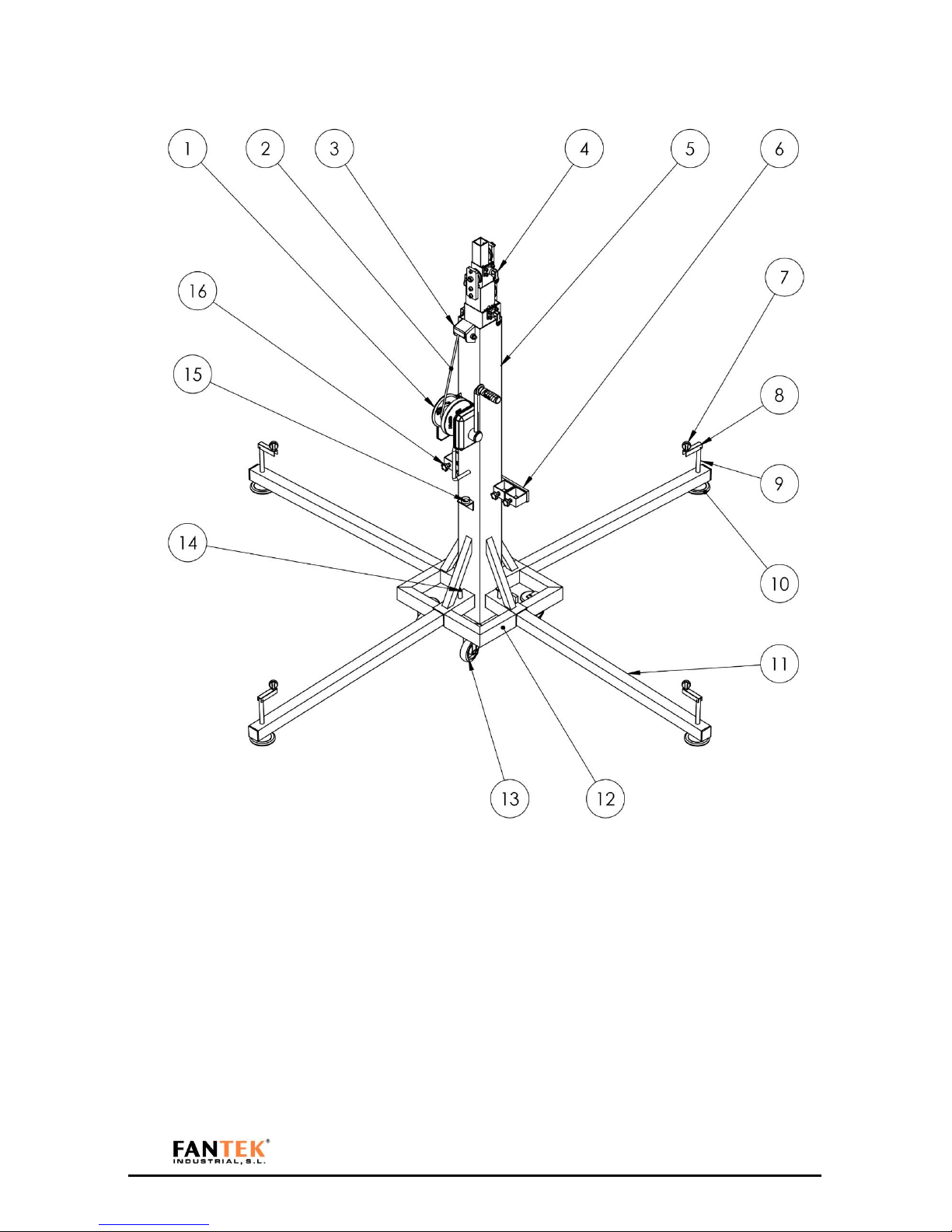
PARTS IDENTIFICATION...................................... 8
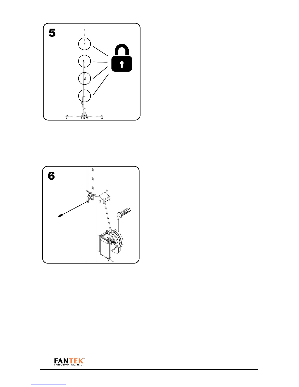
HOW TO USE. STEP BY STEP............................... 9
ACCESSORIES.................................................... 11
.STANDARDS..................................................... 14
LOAD DATA ...................................................... 15
DYNSYS SYSTEM............................................... 16
MAINTENANCE................................................. 17
TRANSPORT...................................................... 18
With forklift..................................................18
With truck or container. .............................. 19
DGUV V17/18 NORM REGULATION................. 20
ESPECIFICACIONES / ESPECIFICATIONS............ 40
DECLARACION DE CONFORMIDAD /
DECLARATION OF COMFORMITY..................... 41
MARCADO DGUV / DGUV MARK ..................... 42
CONTACT
Internet: www.fantek.es
e-mail: [email protected]et
ILLUSTRATION INDEX
Figure 1.............................................................. 3
Figure 2.............................................................. 3
Figure 3.............................................................. 3
Figure 4.............................................................. 3
Figure 5.............................................................. 4
Figure 6.............................................................. 4
Figure 7.............................................................. 4
Figure 8.............................................................. 4
Figure 9.............................................................. 5
Figure 10............................................................ 5
Figure 11............................................................ 5
Figure 12............................................................ 5
Figure 13............................................................ 6
Figure 14............................................................ 6
Figure 15............................................................ 6
Figure 16............................................................ 6
Figure 17............................................................ 7
Figure 18............................................................ 7
Figure 19............................................................ 8
Figure 20............................................................ 9
Figure 21............................................................ 9
Figure 22............................................................ 9
Figure 23............................................................ 9
Figure 24.......................................................... 10
Figure 25.......................................................... 10
Figure 26.......................................................... 11
Figure 27.......................................................... 12
Figure 28.......................................................... 13
Figure 29.......................................................... 14
Figure 30.......................................................... 15
Figure 31.......................................................... 16
Figure 32.......................................................... 17
Figure 33.......................................................... 18
Figure 34.......................................................... 19
ENG

USER MANUAL FOR UPSIDE LOAD TOWERS 3
RULES AND SAFETY USE
Figure 1
Keep hands and fingers away from moving parts of
the tower.
Figure 2
Not charge the tower without the legs stabilizers
lowered.
Figure 3
Do not lift the tower without proper leveling. To lift a
load, the tower must always be stabilized. The wheels
must not touch the ground.
Figure 4
Place the tower on a stable Surface.
If the ground has a low degree of compaction (earth,
gravel, etc..) consult the section of load data.

USER MANUAL FOR UPSIDE LOAD TOWERS 4
Figure 5
Do not use the tower on tilted surfaces that require
pieces to level the tower.
Figure 6
Before placing a load, make sure that the load never
exceeds the maximum allowed. Consult the section of
load data
Figure 7
Never move a load without level.
Figure 8
Do not use ladders on the tower or leaning against it.

USER MANUAL FOR UPSIDE LOAD TOWERS 5
Figure 9
Not grease and lubricate the mechanism of the winch
and the pulleys of the masts.
Figure 10
Not allowed to lift people or animals.
Figure 11
Do not stand under the load. The load must be
secured to the tower in order to prevent that the load
cannot fall down.
Figure 12
Verify that the tower is beyond the reach of power
lines.
The tower is not electrically insulated and can
transmit currents of power lines.

USER MANUAL FOR UPSIDE LOAD TOWERS 6
On the following table is recommended the average
length between the highest part of the structure and
the power lines.
Voltage
Min. distance
Between phases
Meters
Feet
0 a 230v
1.5
4.92
230v a 400v
2.8
9.19
400v a 50Kv
3.4
11.15
50Kv a 200Kv
4.9
16.08
200Kv a 350Kv
6.5
21.33
350Kv a 500Kv
8.2
26.90
500Kv a 750Kv
11.3
37.07
750Kv a 1000Kv
14.2
46.59
Figure 13
Not use the tower as welding mass.
If necessary, use the grounding placed on the base.
Figure 14
Not lift a load if there is danger of collision. Take at
least 1.5 meters on any direction to lift safety the
load.
Figure 15
The tower can be used outdoor if the wind speed is
low and If it doesn’t put the installation in risk. The
installation is always under responsibility of the
owner.
Figure 16
Do not use the tower as a support of banner or
another type of decoration with strong wind. That can
destabilize the tower and make it fall down.

USER MANUAL FOR UPSIDE LOAD TOWERS 7
Figure 17
Do not lift structures that require more than one
tower at different speeds
V1
≠
V2
No lift
V1
=
V2
Ok
Figure 18
The structure must be levelled correctly. If not, the
structure can fall.
Always h1 = h2

USER MANUAL FOR UPSIDE LOAD TOWERS 8
PARTS IDENTIFICATION
Figure 19
1
Winch
11
Leg
2
Cable
12
Base
3
Wire Drive
13
Weel
4
Security system
14
Base lock
5
Mast
15
Spirit level
6
Leg carrier
16
Leg knob
7
Level knob
8
Level handle
9
LEvel screw
10
Level plate

USER MANUAL FOR UPSIDE LOAD TOWERS 9
HOW TO USE. STEP BY STEP
Figure 20
Fix and secure the legs stabilizers to the base.
Figure 21
Level the tower. Ensure that the wheels never contact
the ground.
Figure 22
Unlock the security system to start to lift.
Figure 23
Move the handle of the winch to lift the tower.
When the section reaches its limit, lock with the
security system and unlock the following security
system to lift the next mast. Do the same operation
until you reach the required height.

USER MANUAL FOR UPSIDE LOAD TOWERS 10
Figure 24
All security systems must be in locked position.
Slacken the cable of the winch for the system can
stabilize correctly.
Figure 25
To lower the load. Tighten the cable and unlock the
first security system. Turn the winch while
maintaining the other hand unlocking security
system.

USER MANUAL FOR UPSIDE LOAD TOWERS 11
ACCESSORIES
The towers have the following accessories.
Figure 26
TRUSS
ATCMOS
ATC30S
ATC25S
ATCTS
ES
X
X
X
25 to 30
ER
25 to 45
30
25
X
EC
25 to 52
30
25
X

USER MANUAL FOR UPSIDE LOAD TOWERS 12
Figure 27
T106 model with ATC6FS accessory.

USER MANUAL FOR UPSIDE LOAD TOWERS 13
Figure 28
T106 model with ATCMOS accessory.

USER MANUAL FOR UPSIDE LOAD TOWERS 14
.STANDARDS
Figure 29

USER MANUAL FOR UPSIDE LOAD TOWERS 15
LOAD DATA
Following can be found the maximum loads to be borne by each tower model for maximum working height.
TOWER
T100D
T101D
T102D
T103D
T104D
T105D
T106D
LOAD
lbs
220
220
220
331
441
496
496
kg
100
100
100
150
200
225
225
Figure 30
Load table

MANUAL DE USIARIO PARA TORRES DE CARGA SUPERIOR 16
DYNSYS SYSTEM
The Dynsys system is an optional solution to control the maximum load in our tower lifters.
The Dynsys limits the máximum load avoiding to lift a load bigger than the máximum load. The limitation
is do it for use as a machine system. For more information about the máximum load, check the load
table.
In case of lift a load bigger than the máximum of the tower, the Dynsys detects the incriase of load and
stops the elevation. In that case the load only can go down.
In case of limitation, the Dynsys advise with noise.
The Dynsys Works like a preventive maintenance. If the tower works with problems like damaged
internals, bad state of steel wire, the dynsys limits the maximum load decreasing it till the tower works
fine. If this happens, please contact with technical department or your local distributor.
The system allows to dismantle the lever. You can block the tower removing the lever. This is a form to
ensure that nobody alien to the show can move the tower up or down. You only need to remove the
Allen screws.
Figure 31

MANUAL DE USIARIO PARA TORRES DE CARGA SUPERIOR 17
MAINTENANCE
Figure 32
Cable damaged detail.
Check periodically the state of the cable. If the cable is broken must be replaced immediately with a new one. Do not
use the tower with a cable shabby. If any doubt, contact with Fantek Industrial S.L.
In case of replacement of pieces. Replace only original parts Fantek Industrial S.L. Otherwise, the warranty is voided.
Is recommended a review of the tower by specialized staff of Fantek Industrial S.L. once a year.
To request any spare must attach the reference of the piece included in the spare manual that can be obtained in

MANUAL DE USIARIO PARA TORRES DE CARGA SUPERIOR 18
TRANSPORT
To the transport of the towers:
-Verify that the legs stabilizers are securely fixed to the tower in the transport and they cannot be released.
-Check that all sections are locked.
With forklift
To transport the towers with a machine type forklift the ATCTT106 accessory is necessary. Follow the instructions of
the machine operator transport manual. Take into account the height of what is transported. Avoid sudden turns
and braking.
Figure 33
Detail of transport with forklift.

MANUAL DE USIARIO PARA TORRES DE CARGA SUPERIOR 19
With truck or container.
For the transport by truck or container, always tie the tower by two points. Use ratchets not less than 250 kg of
force.
Place ratchets so that the tower cannot move by inertia in curves or sudden braking.
Figure 34
Detail tower place and shape holding.

MANUAL DE USIARIO PARA TORRES DE CARGA SUPERIOR 20
DGUV V17/18 NORM REGULATION. Explanation
DGUV V17/18 is a norm that regulates the stage and production elements in the entertainment industry. Lifting
equipment and rigging are part of this norm and cover structures and other technical elements.
Adopt DGUV V17/18 is totally voluntary (except in Germany) but its adoption is required by insurance companies
and indeed is becoming a norm in the industry
The application of this norm on lifter towers is vital because, in theaters, stages, etc.., are used to move loads above
artists, technical staff, etc... and in some cases, above viewers, representing a potential risk of fall.
NORM DGUV V17/18. Fields of application
This standard is oriented in two ways:
On the one hand, lifting towers adopt designs and materials in order to achieve a high degree of safety in
quantities such as supported load, equilibrium, resistance to friction, etc.
Thus lifter towers FANTEK DGUV V17/18 certified, they assure the user that have passed strict controls during
design, choice of materials or load checks and effort.
On the other hand, in order to achieve optimal performance with these units, it is recommended, and a
responsible use of the unit, (meeting basic norms such as obey the maximum load or balance), periodic
maintenance which It must be carried out by expert technicians, checking the condition of the steel cable and
winch, the functioning of the security pins and the folding/unfolding of all sections.
All the above tests are only mandatory in those countries with specific regulations on the matter, applied through
regulations or laws. As manufacturers, we recommend passing all tests in order to prevent damage and ensure
proper operation of P.A. lift systems.
This manual suits for next models
6
Table of contents
Languages:
Other Fantek Lifting System manuals
Popular Lifting System manuals by other brands

CLAS
CLAS PE 6004 manual

Central Hydraulics
Central Hydraulics 1647 Assembly and operating instructions

Challenger Lifts
Challenger Lifts 4030SFX Installation, operation & maintenance manual

Genie
Genie Lift Tools GS-2669 Operator's manual

Atlas
Atlas PV-10PX Installation & operation manual

SCANCLIMBER
SCANCLIMBER SC2000K manual

Harmar Mobility
Harmar Mobility Single-Fold Ramp Installation and owner's manual

ATN
ATN MYGALE 23 Translation from the original manual

JLG
JLG 600SJ Service and maintenance manual

EINHELL
EINHELL TC-EH 1000 Original operating instructions

Atlas
Atlas 414 Installation & operation manual

Leyman
Leyman Hide-A-Way LHS2500 installation manual