Stratus SAE-UT9000 Guide

Model No. SAE-UT9000
Full Rise Ultra Thin
Scissor Lift
Lifting Capacity 9000 lbs
Installation & Operation &
Maintenance Instructions
Important Note
1. This equipment can not be installed, operated or repaired without reading instructions.
2. Electricity must be hooked up by certified electrician.
3. Do not use this equipment beyond its rated capacity.

STRATUS Full Rise Scissor Lift Installation & Operation & Maintenance Instructions
2
TABLE OF CONTENTS
1. Safety instructions...........................................................................................................................................................4
1.1 Important declarations.................................................................................................................................................4
1.2 Qualified operator and user illustrations....................................................................................................................4
1.3 Danger notices..............................................................................................................................................................4
1.4 Warning signs................................................................................................................................................................5
1.5 Noise standard..............................................................................................................................................................5
1.6 Training...........................................................................................................................................................................5
2. Product overview..............................................................................................................................................................6
2.1 Product description.......................................................................................................................................................6
2.2 Specifications................................................................................................................................................................6
2.3 Construction of the Lift.................................................................................................................................................6
3. Installation instructions..................................................................................................................................................7
3.1 Preparations before installation..................................................................................................................................7
3.2 Precautions during Installation ...................................................................................................................................9
3.3 Installation steps......................................................................................................................................................9
4. Operation instructions ..................................................................................................................................................15
4.1 Operation precautions................................................................................................................................................15
4.2 Operation control panel instructions...................................................................................................................15
4.3 Flow chart for operation........................................................................................................................................16
4.4 Operation instructions...........................................................................................................................................16
4.5 Emergency Lowering............................................................................................................................................17
5. Trouble Shooting............................................................................................................................................................20
6. Maintenance.....................................................................................................................................................................21
7. Annex.................................................................................................................................................................................23
Annex 1. Packing List of the whole lift............................................................................................................................23
Annex 2. Overall diagram.................................................................................................................................................23
Annex 3. Hydraulic working system ...............................................................................................................................24
Annex 4. Wiring diagram..................................................................................................................................................25
Annex 5. Diagram for air supply connection.................................................................................................................30
Annex 6. Exploded view of the whole lift.......................................................................................................................30
Annex 7. Common spare parts list .................................................................................................................................35

STRATUS Full Rise Scissor Lift Installation & Operation & Maintenance Instructions
3
Foreword
Notes on the operating instructions
The present ORIGINAL OPERATING INSTRUCTIONS are designed to provide sufficient instruction for the
safe operation of the product. The information is provided clearly and concisely. The chapters are arranged
by letter and the pages are numbered continuously.
Our products are subject to ongoing development. Our company reserves the right to alter the design,
equipment and technical features of the system. No guarantee of particular features of the product should
therefore be assumed from the present operating instructions.
Safety notices and text mark-ups
Safety instructions and important explanations are indicated by the following graphics:
Indicates an extremely hazardous situation. Failure to comply with this instruction will result in
severe irreparable injury and even death.
Indicates an extremely hazardous situation. Failure to comply with this instruction may result in
severe irreparable injury and even death.
Indicates a hazardous situation. Failure to comply with this instruction may result in
slight to medium injury.
Indicates a material hazard. Failure to comply with this instruction may result in material damage.

STRATUS Full Rise Scissor Lift Installation & Operation & Maintenance Instructions
4
1. Safety instructions
1.1 Important declarations
During the warranty period, any quality problem will be properly solved to the user's satisfaction. However, we will
not take any responsibility for whatever bad consequence resulted from improper installation and operation,
overload running or unqualified floor foundation. This lift is specially designed for lifting motor vehicles and not
allowed to use it for any other purposes. Otherwise, we, as well as our sales agent, will not bear any responsibility
of accidents or damages to the lift. Make sure to pay careful attention to the lifting capacity on the label attached
to the lift. Never attempt to lift cars beyond its capacity. Please refer to bellow pictures and table for details.
Read this manual carefully before installation and operation of the machine so as to avoid your property loss or
personnel injury and casualty incurred by the wrong operation. Without the manufacturer’s consent, users are not
permitted to make any modification to the control unit or other mechanical units.
1.2 Qualified operator and user illustrations
•Only the professionally trained person can operate and use the lift.
•Electrical connection must be done by a competent electrician.
•Irrelevant persons are not allowed to be near the lifting area.
1.3 Danger notices
•Do not install the lift on any asphalt floor. The concrete floor should be thick enough to the requirement.
•Read and understand all the operation safety contents before operating the lift.
•The lift is not fit for outdoor use unless it is special tailor-made at the request of the customer.
•Keep hands and feet away from any moving part. To avoid clumping, put your hands and feet away from the
underneath area where the lift is lowering.
•Only the professionally trained person can operate and use the lift.
•Operators are not allowed to wear oversized clothes to avoid being caught by moving parts of the lift.
•Keep the lift surrounding area clean and clear and no stacking to avoid accident happening.
•The lift is designed to lift the entire vehicle but not part of it. Never attempt to lift any cars beyond its capacity.
Model
A
B
C
D
E
F
G
SAE-UT9000
1900mm
(74.8”)
2000mm
(78.7”)
120mm
(4.7”)
2400kg
(5291lbs)
1600kg
(3527lbs)
2400kg
(5291lbs)
1600kg
(3527lbs)

STRATUS Full Rise Scissor Lift Installation & Operation & Maintenance Instructions
5
•Make sure the safety latches are in lock position before any attempt to work near or under the vehicle.
•Place the lifting pads to the positions suggested by vehicle makers. Operators are required to increase the
vehicle slowly to make certain it will not slant, roll-over or fall off before lifting the vehicle to the desired
height.1.3.11Always keep checking the lift in case of any damage of the parts. Check the machine
synchronization performance and the agility of moving parts. Do the regular maintenance. If any abnormal
occurs, stop using the lift immediately and contact our dealers for help.
•When operation is finished, descent the lift to its lowest position and cut off the power source
•It is prohibited to modify or change any parts of the lift without manufacturer’s consent.
•If the lift is to stop using for a long time, users are required to:
a. Disconnect the power source;
b. Empty the oil tank;
c. Lubricate moving parts with the hydraulic oil.
1.4 Warning signs
1.5 Noise standard
Noise Standard of the lift should be less than 75dB。For your safety, it is recommended to put sound meter to your
operation area.
1.6 Training
Only the professional person can operate and use the lift. If professional training from manufacturing factory, we
are willing to help in this aspect.

STRATUS Full Rise Scissor Lift Installation & Operation & Maintenance Instructions
6
2. Product overview
2.1 Product description
This model is on-ground design for user easy installation. Its four cylinders structure makes the lowest 120mm
(4.7”) clearance from ground come true. Its platform extension deign is not only used as a ramp, but also serve as
an extended part of the platform for much longer vehicles. Besides, designs like, 24V working voltage of control
box and limit switch, alarming buzzer from floor 500mm (19.7”), pneumatic safety lock, anti-surge valves, etc.
have fully considered your personal security.
Safety structure:
2.2 Specifications
Model
Lifting capacity
Lifting time
Lifting height
Electrical requirement
SAE-UT9000
4000kg
(9000lbs)
50 Sec
2040mm
(80.3”)
220V/240V/1Ph
380V/415V/3Ph
2.3 Construction of the Lift

STRATUS Full Rise Scissor Lift Installation & Operation & Maintenance Instructions
7
3. Installationinstructions
3.1 Preparations before installation
3.1.1Tools and equipment needed
√ Electrical drill
√ Open wrenchesФ17, Ф19
√ Screw drivers
√ Anti-wear hydraulic oil (AW32/AW46)
3.1.2 Check List of parts ---Annex 1(Whole lift Packing list)
Open the package and check if all parts as perAnnex 1 are included. Do not hesitate to contact the dealers or
manufacturer in case any part is missing. But if you do not contact us and proceed with installation after
knowing lack of parts, Stratus as well as our dealers will not bear any responsibility for this and will charge for
any parts subsequently demanded by the buyer.

STRATUS Full Rise Scissor Lift Installation & Operation & Maintenance Instructions
8
3.1.3 Ground conditions
The lift should be fixed on a smooth and solid concrete ground with its strength more than 3000psi, tolerance
of flatness less than 5mm (0.2”) and minimum thickness of 200mm (7.9”). In addition, newly built concrete
ground must undergo more than 28days’ cure and reinforcement. The ground and its installation diagram as
follow.

STRATUS Full Rise Scissor Lift Installation & Operation & Maintenance Instructions
9
3.2 Precautions during Installation
•Joints of oil hose and electric wire must be firmly connected in order to avoid leakage and wire loosing
•All bolts should be firmly screwed up.
•Do not place any vehicle on the lift in the case of trial running.
3.3Installation steps
Step1: Remove the outer packing shown above and take the platforms out from the unpacked machine
package and place them in level with a gap of 850mm (33.5”) between them onto the floor foundation prepared.
Uptight four pieces of screws fixed on the wood pallet and take the wood pallet away from another platform. Be
careful not to smudge oil hoses.
Step2: Connect oil hose (This step is extremely important, so do refer to the diagram for of oil hose connection
and understand the following instructions before proceeding)
a. Make sure there is nothing obstructed or dirty left in the hose.
b. Installers have to distinguish where the chief oil hose to be connected by referring to the below two pictures
and have the chief hose connected.
c. See the left picture followed by; two branches of the chief oil hose are going to be respectively connected to
the tie-ins for chief oil hose reserved on the hydraulic block and the other scissor. Similarly, branches of the
other two leveling hoses are going to be connected to the tie-ins reserved for leveling hoses.
d. Check if all connections are sealed well.

STRATUS Full Rise Scissor Lift Installation & Operation & Maintenance Instructions
10

STRATUS Full Rise Scissor Lift Installation & Operation & Maintenance Instructions
11
Step3: Connect the electrical wire and air supply system
Connect exterior wires as per the wiring diagram, with the black for phase wire, the blue for null wire, and the
green -yellow for grounding wire. Connect the compressed air supply (air pressure 0.6~0.8kg/cm2) to the air
inlet of the air pump and then have the air hose of the pneumatic safety lock connected to the pneumatic
solenoid valve outlet of the pump.

STRATUS Full Rise Scissor Lift Installation & Operation & Maintenance Instructions
12
Step4: Fill up hydraulic oil Pour into the oil tank with 18 liters of anti-grinding oil.
The oil level shall be 10mm to 40mm away from the top of the tank. (Users can measure it by the feeler
attached on the lid)
Step5: Leveling Attention:
Level the platforms before connecting height limit switch. Otherwise, platforms can not rise to the highest
position. Firstly, make sure the oil hoses are correctly connected. Oil cylinders cannot work synchronously or
could be damaged in result of wrong connections. Secondly, Operators can tell the platforms are controlled by
which leveling valves or buttons through the oil hose connection or trial lifting.
Manual leveling
Open one leveling valve and press the UP button to fill oil to the related oil hose. Close the valve to stop filling
oil. In normal working condition, both leveling valves are closed. With both valves open, the platform can still
raise but not synchronously.
A.Both valves open B. Both valves closed:Normal working
C D
One valve open, the other closed: leveling status

STRATUS Full Rise Scissor Lift Installation & Operation & Maintenance Instructions
13
Leveling method:
1. Open both leveling valves and press the UP button to have both platforms raised to the highest positions.
Repeat this step for two or three t times. This step could take time because there’s air in cylinders and no load
on platforms.
2. Close both leveling valves as per drawing B.
3. Press the UP button to see if both platforms rise synchronously. (Normally, platforms may not rise
synchronously at this point.)
4. If not working synchronously, one platform must rise faster than the other. (Users have to know which
leveling valve controls which platform for both valves by the way of the oil hose connected.)
5. Open the leveling valve that controls the slower-rising platform. Press the UP button till the platform rise to
the same height. (The other valve at his point should be closed.)
6. Close both leveling valves.
7. Press DOWN I button to have both platforms lower to the lowest position. In case they do not lower
synchronously, open the valve that controls the slower-lowering platform and press DWON I button to have it
lower to the lowest position and then close the leveling valve. If the lift is equipped with a height limit switch,
press DOWN II button when platforms stop lowering at a height of 500mm from the ground.
8. Make sure both leveling valves are closed. Press the UP button to check the synchronization of platforms.
9. Repeat 5 and 8 until synchronization is achieved.
Step6: Connect the limit switch use the screw to fix the shield of the limit switch. Connect the quick
connectors of the limited switch with the control cabinet. Finally screw firmly the fixing clip of the oil hose and
put the oil hose, air pipe, etc. in to the clip and clamp tightly. Till now, the connection of the machine is done.
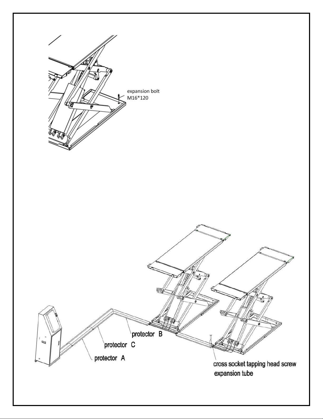
Step7: Fix expansion bolts (according to the above installation position on the floor foundation diagram).
1. Use an electrical drill to drill anchor holes for expansion bolts. Make sure to drill vertically.
2. Ascertain the bottom plate align with the marked line during drilling. After drilling, remove thoroughly the
debris and dust in holes
3. Put the expansion bolts into the drilled holes and use hammer to hit them inside and then tighten them.
STRATUS Full Rise Scissor Lift Installation & Operation & Maintenance Instructions
14
Step8: Install oil hose protectors
Place oil hose guard plates according the bellow picture. There is five pieces in total. Drill installation holes for
expansion plugs according to the reserved holes on protectors of the oil horse. Remove the debris and dust.
Put the expansion plugs under protectors and then tighten the tapping screws on protectors.

STRATUS Full Rise Scissor Lift Installation & Operation & Maintenance Instructions
15
4. Operation instructions
4.1 Operation precautions
1. Check all the joints of oil hose. Only when there is no leakage, the lift can only be used.
2. If there is any problem with the safety device, the lift shall not be used.
3. Check if the gravity center of the vehicle is in the center of the lift platform. Otherwise, adjust it to the center
and then run the lift.
4. Operators and other personnel concerned should stand in a safety area during lifting and lowering process.
5. When the operator leaves the control console after the platforms are raised to the desired height, switch off
the power to prevent any wrong operation by unconcerned people.
6. Make sure the safety lock of the lift is engaged before start working under the vehicle and no people are
under the vehicle during lifting and lowering process.
4.2Operation control panel instructions

STRATUS Full Rise Scissor Lift Installation & Operation & Maintenance Instructions
16
4.3Flow chart for operation
4.4Operation instructions
Raise the lift
1. Make sure that you have read and understood the operation manual before operation.
2. Park the vehicle in the middle of the platforms.
3. Place the four rubber pads under the prop-points of the vehicle and ensure car’s gravity is on the rubber
pads.
4. Press slightly the UP button on the control box until rubber pads have touched the prop-points of vehicle.
5. Keep on pressing the UP button to lift the vehicle a bit higher from the ground and check again if the vehicle
is in a safe position.
6. Having raised the vehicle to the required height, operators must press the “Emergency stop” button until the
power indicator is off and check again the stability of the vehicle before performing maintenance or repair work,
Rising
Lowering
Start
Start
Turn on the Power Switch
Turn on the Power Switch
Press UP Button
Motor Starts
Gear Pump works
Lift rises
Press Down Button I
Press DOWN button when the
lift stops automatically
above500mm from floor
Lift lowers

STRATUS Full Rise Scissor Lift Installation & Operation & Maintenance Instructions
17
Lower the lift
1. Switch on emergency stop switch.
2. Press the DOWN I button to lower the lift. It will stop lowering when clearance between the platforms and the
ground reaches to 500mm.
3. Press DOWN II button to continue lowering the platforms. Alarming buzz is triggered if it is equipped with
safety alarm device.
4. Descent platform to its lowest point. Drive the vehicle away
4.5Emergency Lowering
Pneumatic lock is not engaged
1. Pull the safety lock teeth with certain tools to prevent it from engaging the teeth bar.
2. Use a wench to unscrew loose the spool of the solenoid unloading valve fixed on the hydraulic station.

STRATUS Full Rise Scissor Lift Installation & Operation & Maintenance Instructions
18
Pneumatic safety lock is engaged.
1. Take down the removable plug from the hydraulic block.
2.Connect to the upper separate jack
3.Pull the safety lock teeth with certain tools to prevent it from engaging the teeth bar.

STRATUS Full Rise Scissor Lift Installation & Operation & Maintenance Instructions
19
4. Use a wench to unscrew loose the spool of the solenoid unloading valve fixed on the hydraulic station.

STRATUS Full Rise Scissor Lift Installation & Operation & Maintenance Instructions
20
5. Trouble Shooting
ATTENTION: If the trouble could not be fixed by yourself, please do not hesitate to contact us for help.
We will offer our service at the earliest time we can. By the way, your troubles will be judged and
solved much faster if you could provide us more details or pictures of the trouble.
TROUBLES
CAUSE
SOLUTION
Motor does not run and
will not raise
The wire connection is loose.
Check and make a good connection.
The motor is burnt
Replace it.
The limit switch is damaged or the wire
connection is loose. Moving not smooth.
Connect it or adjust or replace the limit
switch.
Motor runs but will not
raise
The motor run reversely.
Check the wire connection.
Overflow valve is loose or jammed.
Clean or adjust it.
The gear pump is damaged.
Replace it.
Oil level is too low.
Add oil.
The oil hose became loose or dropped off.
Tighten it.
The cushion valve became loose or jammed.
Clean or adjusts it.
Platforms go down slowly
after being raised
The oil hose leaks.
Check or replace it.
The oil cylinder is not tightened.
Replace the seal.
The single valve leaks.
Clean or replace it.
The overflow valve leaks.
Clean or replace it.
Electrical unloading valve leaks.
Clean or replace it.
Raising too slow
The oil filter is jammed.
Clean or replace it.
Oil level is too low.
Add oil.
The overflow valve is not adjusted to the right
position.
Adjust it.
The hydraulic oil is too hot (above 45°).
Change the oil.
The seal of the cylinder is abraded.
Replace the seal.
Lowering too slow
The throttle valve jammed.
Clean or replace.
The hydraulic oil is dirty.
Change the oil.
The anti-surge valve jammed.
Clean it.
The oil hose jammed.
Replace it.
Table of contents
Other Stratus Lifting System manuals

Stratus
Stratus SAE-C10C Guide

Stratus
Stratus SAE-P166M Guide

Stratus
Stratus SAE-F14X Guide

Stratus
Stratus SAE-F12X Guide

Stratus
Stratus MS9000XT User manual

Stratus
Stratus SAE-P410 User manual

Stratus
Stratus SAE-C10P Guide

Stratus
Stratus SAE-C10XE Guide

Stratus
Stratus SAE-C12XE Guide

Stratus
Stratus SAE-C14X Guide


Popular Lifting System manuals by other brands

Nussbaum
Nussbaum 4.55 SL Operating Instruction and Documentation

Doka
Doka Staxo 40 Original operating instructions

VALLEY CRAFT
VALLEY CRAFT ROTOLIFT-78 AIR instruction manual

Maxon
Maxon 80 Series Maintenance manual

EAE
EAE EE-6435BWF Installation, operation, and parts manual

Walker Magnetics
Walker Magnetics NEO-1000 Operation manual


