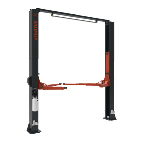
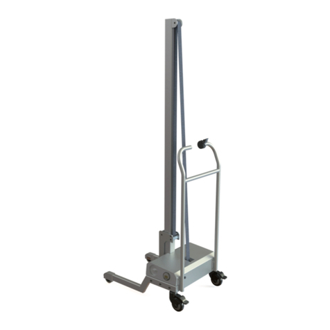
Stratus SAE-F10S Installation instructions

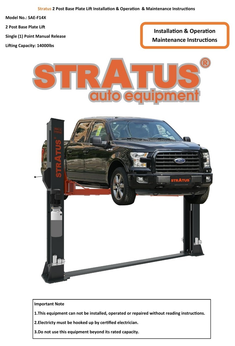
STRATUS 2 Post Li Installaon/Operaon &Maintenance Instrucons
Model No.:SAE-F10S
Two Post Li
Manual Single Point Lock Release
Liing Capacity:10000 LBS
Installaon &Operaon
Maintenance &Instrucons
Important Note
1.This equipment cannot be installed, operated or repaired without reading instrucons.
2.Electricity must be hooked up by cered electrician.
3.Do not use this equipment beyond its rated capacity.

2
CONTENTS
1-The main features of the equipment………………………………………………………………………………………3
1.1-Product descripon………………………………………………………………………………………………………3
1.2-Features of the product…………………………………………………………………………………………………3
1.3-Satey mark of the product………………………………………………………………………………………………3
2-Technical Date of the equipment…………………………………………………………………………………………4
2.1-Product Dimensions………………………………………………………………………………………………………5
3-Equipment appearance and dimensions…………………………………………………………………………………5
3.1-Structure……………………………………………………………………………………………………………………5
3.2-Installaon requirement…………………………………………………………………………………………………6
4-Installaon of equipment…………………………………………………………………………………………………7
4.1-Foundaon requirements………………………………………………………………………………………………7
4.2-Installaon steps…………………………………………………………………………………………………………8
4.3-Column Installaon………………………………………………………………………………………………………11
4.4-Installaon of balanced wire rope………………………………………………………………………………………11
4.5-Connect and unlock the thin wire rope………………………………………………………………………………12
4.6-Installaon power unit, lock cover and height adapter bracket……………………………………………………12
4.7-The connecon of the hoses……………………………………………………………………………………………13
4.8-The connecon of the lines……………………………………………………………………………………………13
4.9-Arms installaon…………………………………………………………………………………………………………14
4.10-Filling with hydraulic oil………………………………………………………………………………………………15
5-The operaon debugging of the equipment……………………………………………………………………………15
5.1-Instrucon for operaon………………………………………………………………………………………………15
5.2-Operaon process………………………………………………………………………………………………………15
6-The maintenance and inspecon of equipment…………………………………………………………………………16
7-Troubleshoong of common faults………………………………………………………………………………………17
8-Explosion picture of the product…………………………………………………………………………………………18
8.1-8.7 ……………………………………………………………………………………………………………………18-23

3
1-The main features of the equipment
1.1-Product descripon
This product is a hydraulic li. The product is manual single point lock release, easy to operate. It is suitable for in-
specon, repair and maintenance of a vehicles below 10000LBS.
1.2-Features of the product
When the power unit of the hydraulic li is connected to the power supply ,press the switch, the gear pump works,
and the hydraulic oil pushes the piston rod up, which is brought to the pulley and the pulley and the safety lock
tooth will blink and bite each other during each ascent. At the same me, to ensure that the hydraulic system will
not cause slippage.
1.3-Satey mark of the product
Do not come under the vehicle during
operaon. This can cause injury and
death.
Evacuate to a safe place instantly
the event that the vehicle ps. This
can cause injury or death.
Before lowering the li, check that
there are no obstrucons under the
vehicle or the li arms.
Do not operate damaged equip-
ment.
When the vehicle is lied, do not rock
it as this may dislodge it.
Only trained person may operate
the equipment. Inexperience can
cause accidents.
Do not li a vehicle using on pair of
arms only.
Do not operate the push buon
except the worker.
Do not rock the vehicle when lied. Do
not use a high pressure cleaner to the
vehicle lower part.
To avoid being electrocuted, dis-
connected the main power before
opening the control panel.
To avoid injury, keep your feet clear of
the arms and carriages.
Read and fully understand the man-
ual before using the li.
Not allowed unauthorized persons in
the work area.
Before going under the li. Make
sure that the safety pawls are en-
gaged.
Posion vehicle with center of gravity
midway between adapters.
Make sure that the front and back
balance when placing the car, oth-
erwise the car will fall.
Do not modify the control panel or the
safety funcons as this may impair
their funcon.

4
2-Technical Date of the equipment
Model SAE-F10S
Liing capacity 4500KG/1000lbs
Liing height 2000mm/78 3/4″
Min height 110mm/4 5/16″
Width between columns 2880mm/113 3/8″
Drive through 2572.6mm/101 1/4″
Liing me About 40 Sec.
Lowering me About 30 Sec.
Column thickness 5.5mm / 1/4″
Carriage thickness 5.5mm / 1/4″
The thickness of the square pipe for arm 6mm / 1/4″
arm range 680-1230mm/880-1440mm
Diameter of steel wire rope Φ9mm / 3/8″
Voltage 220V
Power 2.2kW
Frequency 60Hz
Circuit Breaker 1ph
Hydraulic oil 30A
Equipment Weight AW46/AW32
Packing Dimensions 2880×740×810mm
Equipment Weight 610KG/1343lbs

5
3-Equipment appearance and dimensions
3.1-Structure Composion
2.1- Product Dimensions
POS. Name
1Main column assembly
2Sub-column assembly
3Power unit
4Carriage
5An-collision tape
6Two-secon arm assembly
7Three-secon arm assembly
8Floor plate
9Single layer spiral tray
10 Plasc buckle cover
11 Heightening bracket
12 Increase the set

6
3.2- Installaon requirement
Tools required: electric hand drill (drill bits D16 and D18),open spanner (D17-19),movable spanner, Phillips screw-
driver, sloed screwdriver, horizontal instrument, hammer, band tape, etc.
Name Picture
Rotary hammer drill(Φ19)
carpenter's chalk
Hammer
Screw Sets
Level bar
Tap measure
English spanner(12")
Pliers
Ratchet spanner with socket(28#)
Socket head wrench(3#,5#,8#)
Lock wrench
Wrench set(10#,13#,14#,15#,17#,19,24#,27#,30#)

7
4-Installaon of equipment
4.1-Foundaon requirements
Specicaon of concrete must be adhered to the specicaon as following. Failure to do so may result in li and /or
vehicle falling.
◇Concrete must be thickness 200mm minimum and without reinforcing steel bars, and must be completely dry
before li installaon.
◇Concrete must be in good condion and must be of test strength 3500PSI(245kg/cm²)minimum.
◇Floor must be level with no cracks or holes.
Steps of installaon
◇Locaon of installaon
Check and insure the installaon locaon( concrete, layout, space size etc.) is suitable for li installaon.
◇Use a carpenter's chalk line to establish installaon layout of baseplate.

8
4.2- Installaon steps
Step 1:Check the pats before assembly
Packaged li and hydraulic power unit.
Step 2:Move aside the parts and check the parts according to the shipment parts list .

9
Step 3: Spare parts in the accessories box.
Serial
number Name Photo Parameter Quanty
1Arm sha Φ40×168mm 4
2Arm sha elasc cylindrical pin Φ6×50mm 4
3Increased set 1 Φ50×45L 4
4Increased set 2 Φ50×70L 4
5An-collision tape 2
6An-collision tape strip xing screws Hexagon socket screws
M8×30 4
7Expansion screw M20×160L 10
8Plasc gasket 15
9Power unit xing screws Hexagon Screw M8×25L Each 4
10 Manual unlocking lever M10 Each 1
11 Unlock the wire rope 1
12 Wire rope U-shaped chuck M3 1
13 Plasc cable e 15
14 Main column upper limit switch 1
15 Main column upper limit switch xing
screw Phillips round head screws
M5×10L Each 2
16 Locking and unlocking rope seat as-
sembly accessories Each 6
17 User’s manual 1

10
Step 4: Install anchor bolts
Posion the columns on the installaon layout of baseplate. Install the anchor bolts. Check the columns plumbness
with level bar, and adjusng with the shims if the columns are not vercal. Do not ghten the anchor bolts .
Note: Anchor bolts driven into the ground at least 150mm.

11
4.3-Column Installaon
4.3.1- Li the carriage to the rst lock posion to ensure that the mechanical lock is locked in place to facilitate the
installaon of expansion bolts.
4.3.2- According to the dimensions of foundaon, measure the posion of the main and auxiliary columns, check
the posion and dimensions of the boom plate, and drill the expansion screw xing holes, clean up the drilling
dust.
4.3.3 -Check the vercal calibraon of the column by using the horizontal instrument. If necessary adjust the gasket
under the boom plate, and the length of the gasket should be same as the side length of the boom plate pressed
on it.
4.3.4 -Use expansion bolts to secure the base plate of the column to the foundaon.
4.4- Installaon of balanced wire rope
4.4.1- Firstly adjust the two sides of the carriage to the same height.
4.4.2 -As the below pictures, connect the wire rope.
4.4.3 -Aer installing the wire rope, adjust the ghtness of the wire rope by adjusng the crew cap of the rope
head, and judge by the sound of the safety on both sides when rising , such as the same sound, indicang that the
debugging has been completed, or through the rising process, the height of the carriage on both sides is the same.
In the process of falling, the carriage drops to the lowest point, and the arm safety lock is completed.
4.4.4 -Use No.1 lithium grease to lubricate the wire rope.( this step cannot be omied).

12
4.5-Connect and unlock the thin wire rope
4.6-Installaon of hydraulic power unit, lock cover, height adapter bracket
No. Name Qty.
1Manual unlocking lever 1
2Unlock the wire rope 1
3Locking and unlocking rope seat
assembly accessories 6
4Unlock the rope seat 2
NO. Name Qty.
1Safety lock cover 1
2Phillips round head screws M6×8 4
3Hex nuts M8 4
4Power unit 1
5Flat pad Φ8 4
6 Spring cushion Φ8 4
7Hex bolts M8×25 4
8Heightening bracket 1
9Socket head cap screws M8×10 2

13
4.7-The connecon of the hoses
4.8-The connecon of the lines
No. Name Qty.
1Main cylinder 1
2Auxiliary cylinder 1
3Hose 1 1
4Hose 2 1
5Power unit 1
6Connecon connector 1

14
4.9-Installaon of the arm
**Important Informaon**
Pressure Valve: Clockwise adjustment increases pressure to make the power unit to have more power,
counterclockwise adjustment decreases pressure to make the power unit to have less power.
Hydraulic Oil ow valve: Clockwise adjustment to speed up, counterclockwise adjustment to slow down.
Pos. Name
1Motor
2Check Valve
3Connect to Hydraulic Hose
4Pressure Valve
5Dump Valve
6Hydraulic Oil Filling Port
7Unloading Valve Stem
8Oil Drum
9Hydraulic Oil Flow Valve
10 Oponal Hydraulic Hose Connecon Hole
11 Power line
12 Limit Switch Wire
Pos. Name Qty.
1Arm combinaon 1
2Arm sha 1
3Tool box (Oponal) 1
4Phillips round head screws M5×8 2

15
4.10-Filling the hydraulic oil
Aenon: Please use the new hydraulic oil.
The capacity of the oil tank is 10L. Do not ll the oil tank completely. The hydraulic oil must be
4/5 or more of the capacity of the oil tank to work normally.
Use 32# in winter and 46# an-wear hydraulic oil in summer.
Suggeson: Replace the hydraulic aer six months, one me once year.
5. The operaon & debugging of the equipment
5.1-Instrucons for operaon
5.1.1 Check all hoses connecons, the equipment can only be used if there is no oil leakage.
5.1.2 The li can not be used if the safety device is not working.
5.1.3 The li can not be used it the center of gravity for the vehicle is not in the center of the liing range, otherwise
manufacturers and distributors will not bear any consequences.
5.1.4 When the li is ascending and descending, the operator and other stas must stand in a safe area.
5.1.5 When the liing arm rises to the required height, the power must be turned o to avoid misoperaon.
5.1.6 If you want to work under the vehicle, make sure that the safety lock is in the occlusion state. When the li is
ascending and descending, no one is allowed to stand under the vehicle.
5.2-Operang Process
5.2.1 Ascending
1. Drive the vehicle, park it with in the range of the liing arm, swing the liing arm to the vehicle support point, and
ensure that the center of gravity of the vehicle is in the center of the four liing arms.
2. Turn on the power switch, press the buon on the hydraulic power unl the pad of the liing arm touches the sup-
port point of the vehicle.
3. Keep ascending, make sure that the vehicle had le the ground, then check the vehicle posion again.
4. When it ascends to the required height, check again whether the vehicle is safe; check whether the safety lock of
the liing arm is occlusion, and whether the carriage also falls on the safety lock. Turn o the power and work under
the vehicle only aer checking.
5.2.2 Descending
1. Before ascending, make sure that there is no people or other obstacles under the vehicle.
2. Turn on the power, press the buon on the hydraulic power unit to rise, the carriage rises from the safety lock,
manually pull the unlocking lever down, and then press the valve stem, the li begins to descend.
3. When descending to the lowest point, the liing arms will open automacally, then drive away aer moving or
retracng all the arms.

16
6-The maintenance and inspecon of the equipment
Pos. Name Methods Period
1Arm Safety lock tooth Manually check the occlusion of the arm safety lock tooth
and whether they can be completely locked. Every day
2Spiral pad combinaon Check the rubber pad, clean and replace also. Every day
3Column safety lock combinaon Check the cooperave relaonship between the safety lock
and the carriage. Every day
4Cylinder and hose connectors Before using the li, check for oil leakage. Every day
5Control buon Check whether the buon ”press to run, hand o and stop”. Every day
6Limit Switch Press the hydraulic power unit’s buon, the li rises, and
when the carriage hits the limit switch, it stops rising. Every day
7Unlock the thin wire rope
Check the synchronizaon and ghtness of the safety lock of
the main and auxiliary columns connected with the thin wire
rope.
Every day
8Wire rope Check the synchronizaon and ghtness of the wire rope,
use No.1lithium base grease for lubricaon. Every day
9Steel wire rope wheel and chain
wheel
Check if the rope & chain wheel lubricated and the circlip is
in the groove.
Every three
months
10 Slider plaorm running track The sliding table running track is lubricated with No.1 lithium
-based grease, and there is no obstacle on the running track.
Every three
months
11 Chains and chain pins Chains and chain pins are condion of the expansion bolts
and the ground. If there is a crack, replace it.
Every three
months
12 Anchor bolts Check the condion of the expansion bolts and the ground, If
there is any looseness, deal with it urgently.
Every three
months
13 Overall The rated load or no-load li lis several rounds, the li
should operate stably without abnormal noise.
Every three
months
14 Hydraulic Oil Replace the hydraulic oil within 6 months of rst use, and
then once a year. Every year

17
7. Troubleshoong of common faults
Fault Reason Methods
Abnormal sound is found.
Are there any abrasion marks inside the col-
umn?
Add some lubricant oil into the
column.
Are there any obstacles in the column? Chin up the obstacles.
The motor does not rotate or
rise.
The cables connecon is not good. Check and connect the lines.
Motor is damaged. Replace the motor.
Limit switch is damaged. Replace the limit switch.
Motor rotated, but does not
rising.
Motor reversal. Correcon of cables connec-
on.
The overow valve is loose or there are obsta-
cles. Adjust and clean.
Gear pump is damaged. Replace the gear pump.
The oil sucon pipe is loose and falls of. Tighten the oil sucon pipe.
The sucon pipe lter is clogged. Clean.
Unload slowly aer rising.
Check if the hose is leaking. Replace the hose.
Cylinder is not sealed. Replace the cylinder.
Retaining valve is not sealed. Clean or replace.
The overow valve is not good. Clean or replace.
The unloading valve of the descending is not
good. Clean or replace.
Rising speed is low.
Oil lter is clogged. Clean or replace.
Oil pressure mixed with air. Replenish the hydraulic oil.
The adjustment of the overow valve is not
good. Adjust.
Hydraulic oil is hoer (above 45 degrees). Replace.
The seal components of the cylinder is dam-
aged. Replace.
The throle valve of the descending is tucked
by the obstacles. Clean or replace.
Descending speed is slow.
Hydraulic oil is not clean. Replace.
There is some obstacles in the hose. Clean or replace.
The hose connectors are struck by the obsta-
cles. Clean or replace.

18
8. Explosion picture of the product
8.1 Appearance explosion picture
Pos. Name Qty. Pos. Name Qty.
1Main column assembly 113 Power unit 1
2Sub-column assembly 114 Limit switch 1
3Block assembly 215 Phillips round head screws M5×10 1
4Two-secon support arm combinaon 216 Phillips round head screws M5×25 2
5Three-secon arm combinaon 217 Upper cover welding 4
6Cylinder 218 Hex bolts M10×30 4
7Cylinder connector 219 Flat pad Φ10 4
8Chain 220 Spring cushion Φ10 4
9Approach board 121 Hex nuts M10 6
10 Hose 2 122 Wire rope 6
11 Wire rope 223 Oil-free bearing 2528 6
12 Hose 1 124 Circlip Φ25 6

19
8.2 Assembling of the safety lock for the main column
Pos. Name Qty. Pos. Name Qty.
1Main column safety lock cover 112 Unlock the rope seat welding 1
2Phillips round head screws M6×8 413 Small nylon wheel 1
3Handball 114 Circlip Φ9 1
4Unlock lever 115 Safety p lock 1
5Hex nuts M10 116 Bolt seat 2
6Circlip Φ20 217 Unlock the handle seat 1
7Safety lock sha 118 Top wire M6×10 1
8Door spring 119 Washer Φ20 1
9Washer Φ20 120 Unlock the rope seat 1
10 Hollow pin Φ6×30 121 Torsion spring 1
11 Phillips round head screws M6×8 222 Unlock the thin wire rope 1

20
8.3 Assembling of the safety lock for the auxiliary column
Pos. Name Qty. Pos. Name Qty.
1Secondary column safety lock cover 111 Top wire M6×10 1
2Phillips round head screws M6×8 412 Unlock the rope seat 1
3Circlip Φ20 213 Torsion spring 1
4Flat pad Φ20 114 Safety lock sha 1
5Door spring 115 Unlock the thin wire rope 1
6Safety p lock 116 Unlock the rope seat welding 1
7Bolt seat 217 Small nylon wheel 1
8Unlock the handle seat 118 Circlip Φ9 1
9Hollow pin Φ6×30 119 Phillips round head screws M6×8 2
10 Washer Φ20 1
Table of contents
Other Stratus Lifting System manuals
Stratus
Stratus MS9000XT User manual
Stratus
Stratus SAE-P166M Guide
Stratus
Stratus SAE-C10C Guide
Stratus
Stratus SAE-S66M User manual

Stratus
Stratus SAE-C10XE Guide

Stratus
Stratus SAE-C12XE Guide
Stratus
Stratus SAE-F12X Guide
Stratus
Stratus SAE-P48 Guide
Stratus
Stratus SAE-C14X Guide
Stratus
Stratus SAE-F14X Guide
