Page 13
Faria Serial Bus Installation and Wiring Guide (Pleasurecraft Engines)
The system consists of:
• One Gateway box to interface with MEFI IV ECU and external senders and sensors.
• One 5” Tachometer with Fuel Monitor
• One 5” Speedometer with Depth Sounder
• One 5” Optional Speedometer
• Various 2” instruments, including but not limited to
• Voltmeter
• Oil Pressure gauge
• Engine Temperature gauge
• Fuel Level gauge
• others as specified.
Installation
Installation of the Faria Serial Bus system is accomplished as follows:
Gateway Box
The “gateway” box is the central unit of the system. As all of the senders and other
information source peripherals connect to the “gateway”, the “gateway” box should be
mounted in a protected area in the best location to provide the maximum cabling
benefit.
The “gateway” box power cable must be installed to allow connection to “battery
positive” (always on), “battery negative” (ground), and a source of “switched power”
which turns on with the engine ignition switch (see Figure 3 and Table 1).
The “Faria Bus” cable must be routed from the “gateway” box to the instrument panel
area to connect the instruments to the data bus and instrument power (see Figure 4).
The remainder of the connections to the “gateway” box are described below.
Instruments
The instruments are mounted using the provided back-clamps and mounting hardware.
Each instrument comes with a bus connection cable (12”). The main “Faria Bus” cable
from the “gateway” box is connected to the most convenient instrument using either of
the two four (4) pin connectors provided on the instrument case (*except when a Faria
Serial Bus Pilot or a Faria Speedometer-PerfectPass Cruise instrument is installed, see
note below).
Each additional instrument is connected to the previous instrument using one of the
12” bus connection cables. The cable may be connected to either of the two connectors
provided on the instrument case (see Figure 2).
The Faria Serial Bus Pilot and the Faria Speedometer-PerfectPass Cruise instruments are
“end of the bus” instruments. Only the provided four (4) pin connector is to be connected to
the “Faria Bus”. See special instructions for use of the six (6) pin connector on these
instruments.
*NOTE:
Page 8
Tachometer / Fuel Monitor
The Serial Bus Tachometer / Fuel Monitor
instrument provides both the functions of a
tachometer and a fuel - engine monitoring
system. The analog tachometer is a stepper
motor instrument which looks like a
standard analog device but which is
actually a digital instrument. On small
pointer movements you may occasionally
see the pointer moving in the one third
degree “steps” that represent the accuracy
of the instrument.
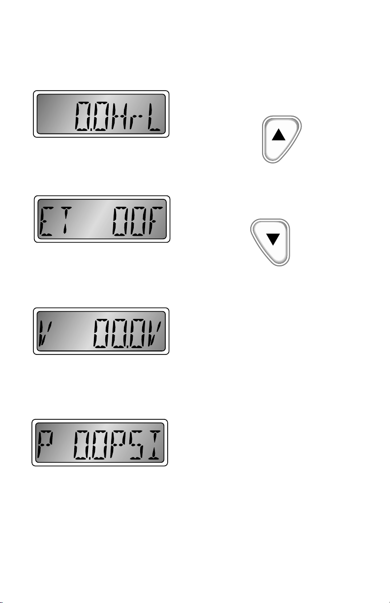
The tachometer LCD screen displays
several functions. The displayed data
includes “engine hours”, “time remaining”,
“engine temperature”, “oil pressure”, “system
voltage”, and engine alarm conditions.
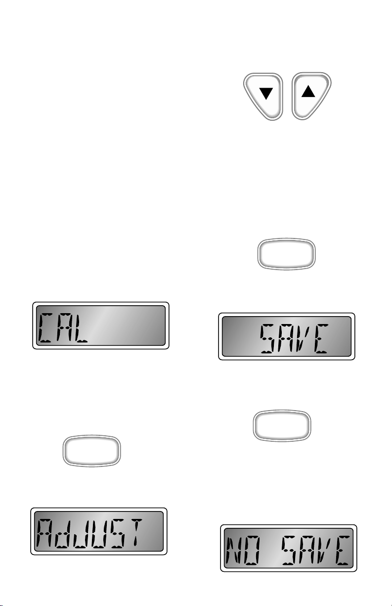
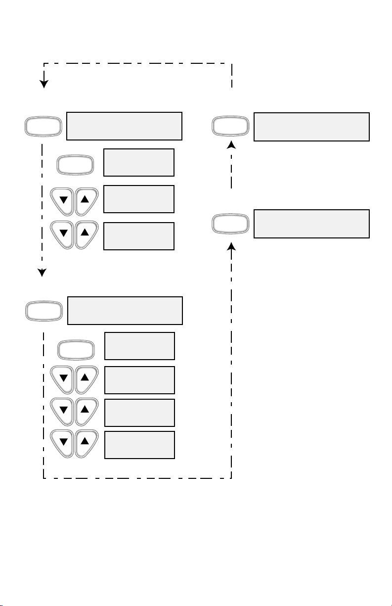
Pressing the “mode M” button will select
the various functions as shown in
Figure 2.
In order to minimize “false” alarms, the
“low fuel” and “low voltage” alarms only
function when the engine is known to be
running based on the presence of
tachometer data.
Several alarm conditions may also be
displayed in the LCD display when
needed:
1 Low fuel
2 Low oil pressure
3 High engine temperature
4 Low voltage
5 Engine RPM reduction due to engine
controller command
6 RPM limit
7 Knock sensing system malfunction
8 Ignition system malfunction
9 Manifold pressure sensor (MAP)
malfunction
10 Manifold temperature sensor
malfunction
11 Throttle position sensor (TPS)
malfunction
12 Coolant sensor malfunction
Alarm messages will be displayed on the
tachometer LCD display. Messages 1-5 will
also include a flashing red light. All
messages will be displayed until either the
problem is corrected or the operator
manually cancels the warning message.
Canceling system alarms
To manually cancel system warning
messages, simultaneously press both the
“Up” and “Down” buttons on the
tachometer.
This will disable the warning message
temporarily. If the problem is not corrected
in 1 minute (5 minutes for low fuel), the
warning will be displayed again. The
operator can cancel as often as desired.
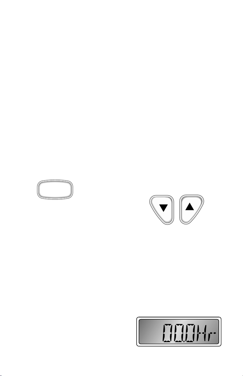
Engine Hourmeter
Displays the number of hours that the
engine has been operated. The display will
show “XXXX.XHr”.
M
Mode
Button
Down
Button
Up
Button