modify the setting.
The microprocessor will automatically
record the new setting as you modify it.
Pressing and holding the “Mode”button
sets the instrument to normal operation.
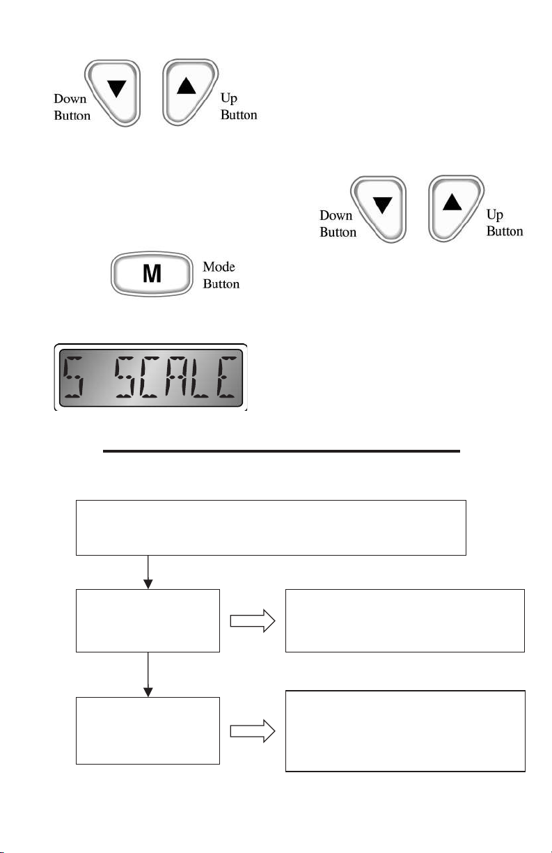
Speedometer Full Scale Selection
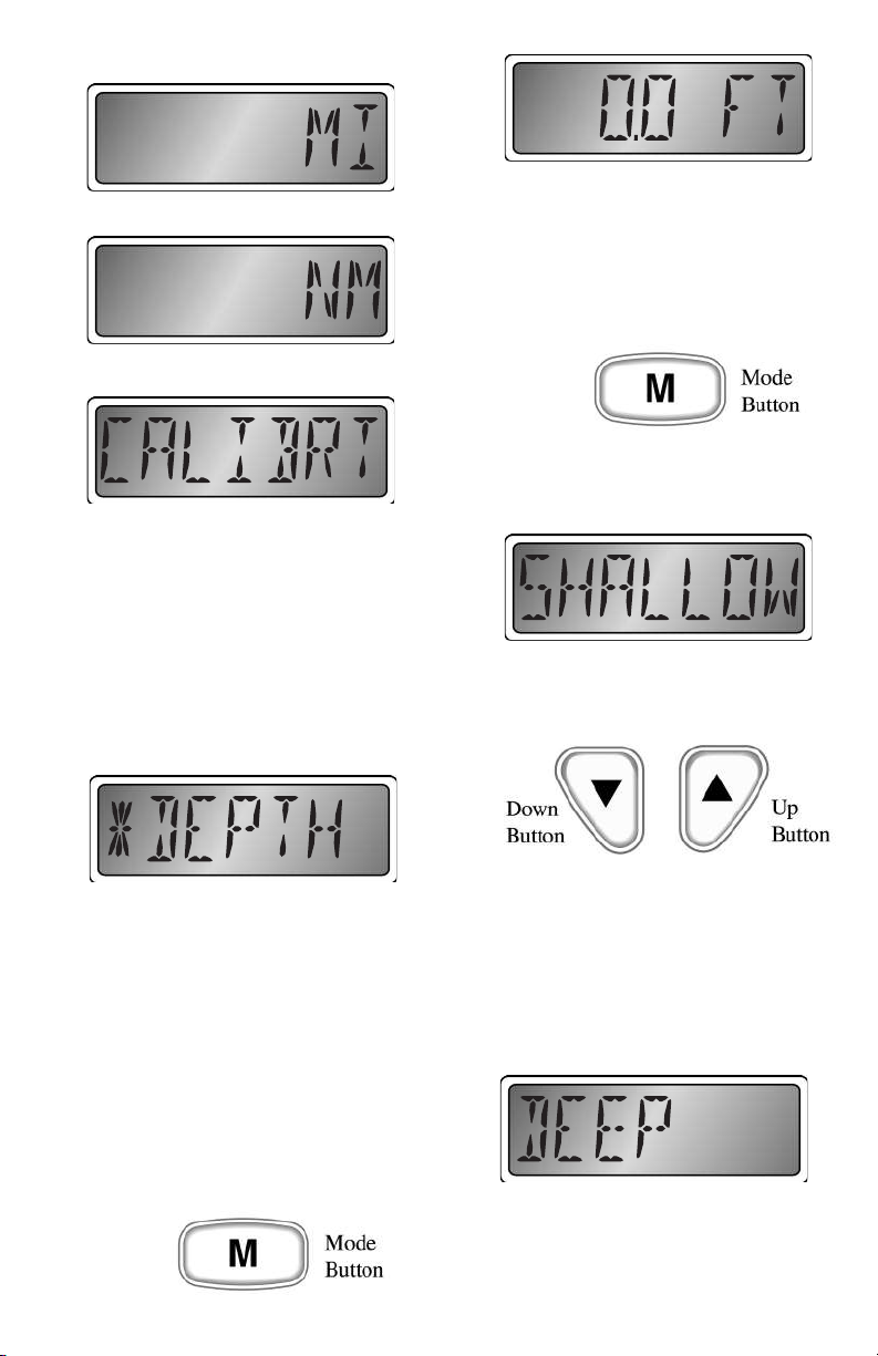
Refer to Figure 1 for an explanation of each
of the speedometer full scale selections.
This is normally a factory setting that
needs no adjustment. The setting adjusts
the “full scale”operating range of the
speedometer to match the dial on the
instrument. Using the “Up”and “Down”
buttons,
adjust the setting to match the maximum
reading on the speedometer dial, 50 or 70
MPH.
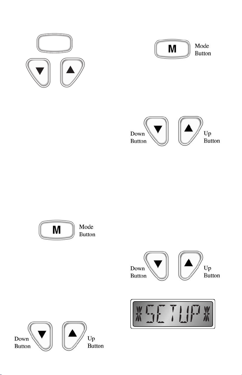
SETUP MODE
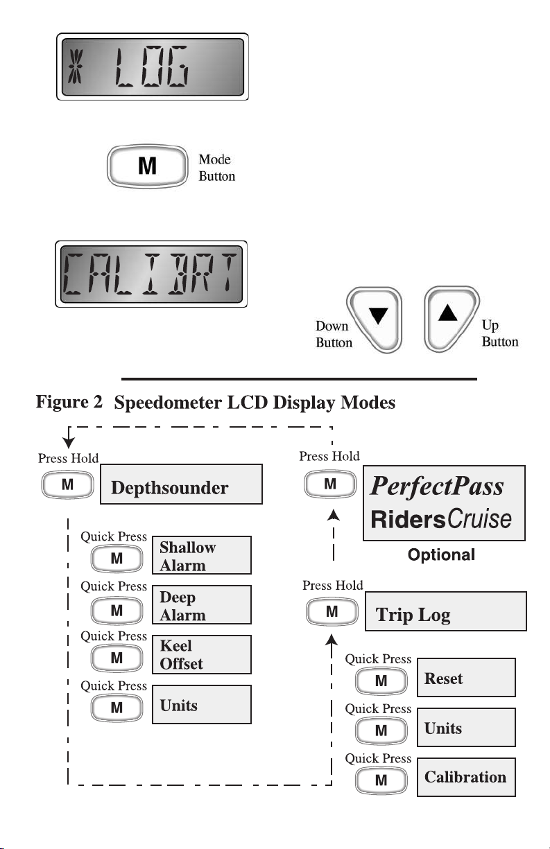
Figure 1
ENTER SETUP MODE:
Press both the “Up” and “Down” buttons while turning on instrument
To exit the setup mode, press and hold the “Mode” Button
SETUP start screen,
shows that setup mode
has been entered.
Flashes “S SCALE”and
then shows current
speedometer scale
selection.
Screen shows:
“50”, or “70”Default = 70
se the “Up” or “Down” button to adjusts
Speedometer full scale reading to match dial
Page 3
PerfectPass® Cruise
The FARIA®Commander™Speedometer
/ Depth Sounder features enhanced control
features for the PerfectPass® Cruise system
as a factory installed option. Check with
you dealer.
Lighting
NOTE: When the instrument is in the
PerfectPass®Cruise mode the “Up”and
“Down”buttons are used for other
functions and do not affect lighting.
The PerfectPass® Cruise system works like
an automotive “cruise”control with On/Off,
Resume, and Decrease/Increase functions.
In addition to the normal PerfectPass
Cruise LED indications the Faria version of
the control unit displays the system status
in the LCD display. Upon entering the
PerfectPass Cruise mode of operation,
“PerfectPass”appears briefly in the LCD
then the current status of the PerfectPass
Cruise system is displayed. There are four
status messages displayed; Off, Ready,
Engaged, and Resume.
When the system is first selected, Off is
displayed. LED remains off.
Pressing the “Up”button turns the system
on.
The display indicates “Ready“and the
LED blinks slowly.
Drive to the desired speed then press the
“Up”button and PerfectPass Cruise takes
over (the display changes to “Engaged”and
the LED stays on). If you pull back on the
throttle, the system immediately disengages
and goes into auto resume mode (the
display shows “Resume”and the LED will
blink rapidly).
If you accelerate back to the previously set
speed, the system will again take over (the
display changes to “Engaged”and the LED
stays on).
Speed changes can be made at any time
the system is “Engaged”by pressing the
“Up”or “Down”buttons.
Page 8