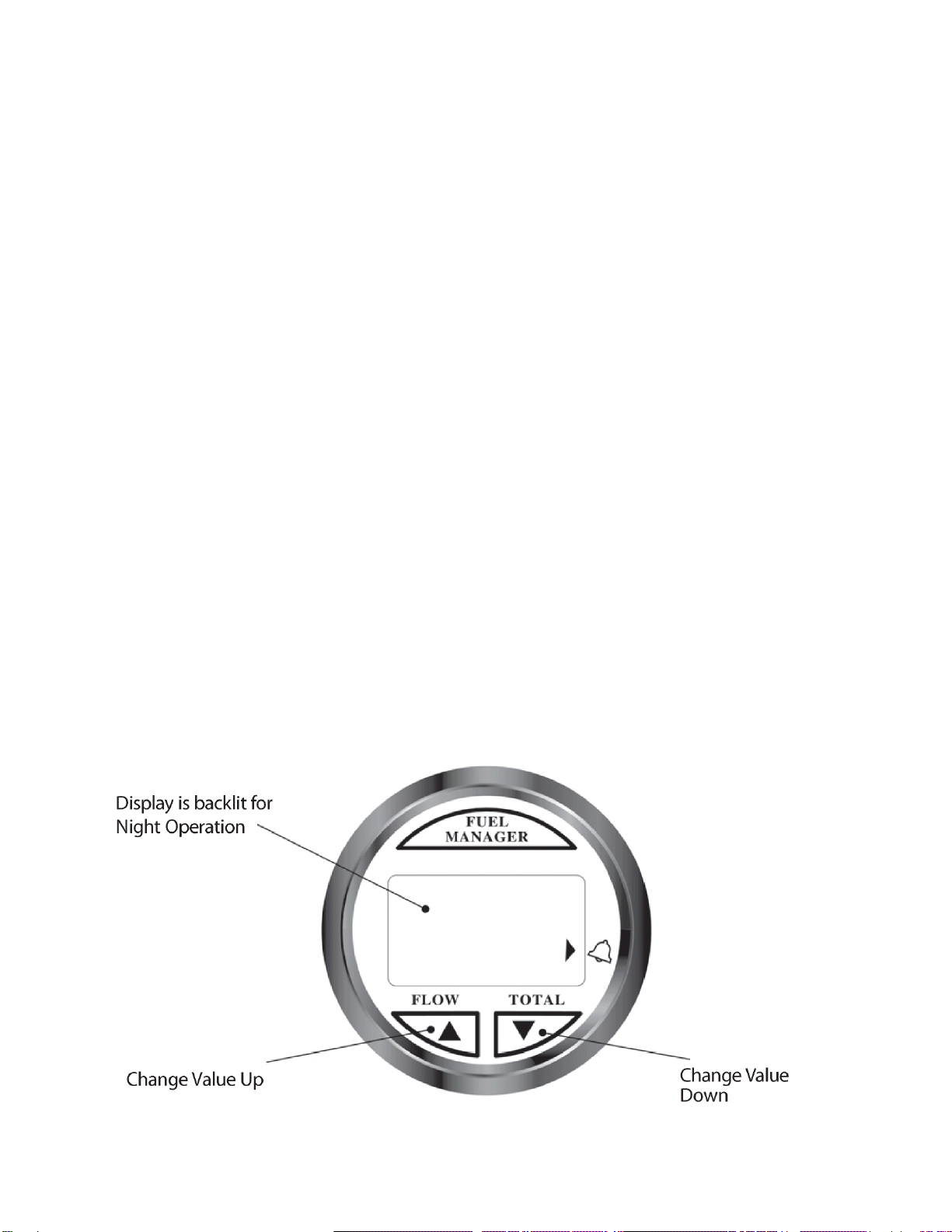
7
Instrument Setup
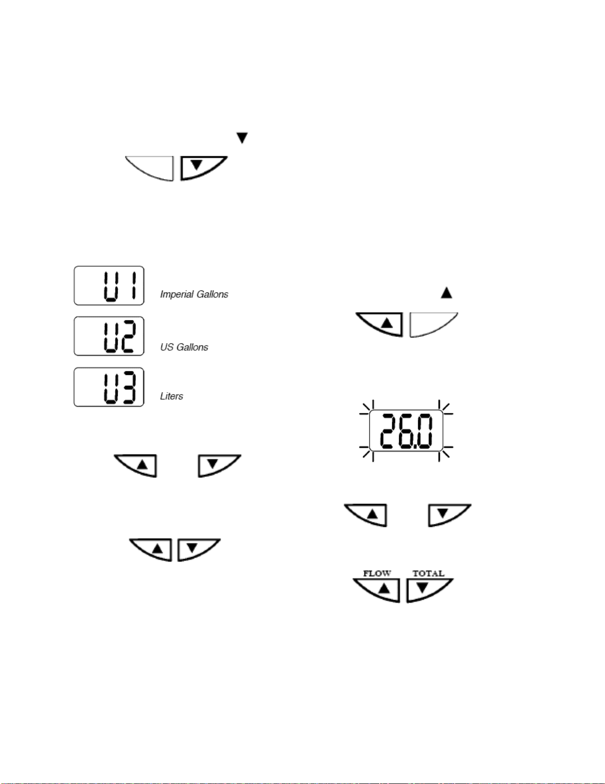
Select units of measure
The Fuel Management fuel flow meter can
display fuel values in US gallons, Liters or
Imperial gallons. To change the current
display setting, perform the following steps.
1. Power up the unit while holding key.
Press and hold during power up
2. Once the unit is on, release the key.
The current display setting is indicated as
pictured below:
3. To select another display setting, use the
up or down keys to change the value.
or
4. To save the change and exit this mode,
press and hold both keys simultaneously
for one second.
Press and hold for one second
The fuel values are now displayed using the
new setting.
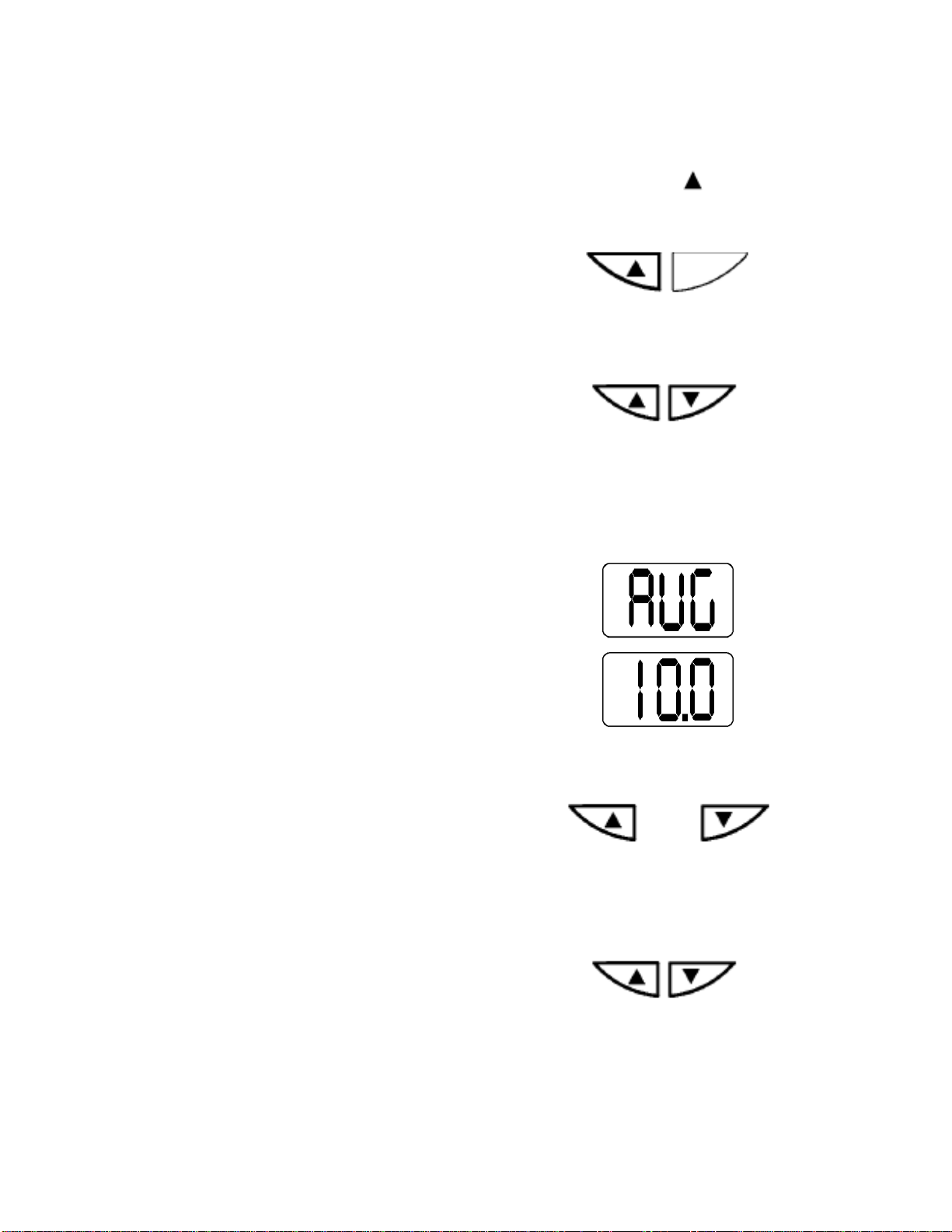
Calibration
The fuel transducer supplied with the fuel
flow meter will provide readings at better
than 5% accuracy. Individual calibration
will increase this level of accuracy to better
than 2% over a fuel flow range of 2 to 32 US
gallons per hour.
While a properly calibrated unit should
provide accuracy within the published limits,
the user should also have a level sender o
fuel level gauge installed in the boat. This is
necessary due to possible operator induced
errors such as forgetting to reset the fuel
used when filling the tank, or other operato
controlled actions that may render the device
inaccurate. Perform the following steps to
calibrate your fuel flow meter:
1. Reset the total log value to zero(see pg 9)
2. Use a known amount of fuel. The larger
the amount the more accurate the
calibration will be.
3. Take note of the actual volume of fuel
used and the fuel used indicated by the
total log. If these two totals are different,
the instrument may require calibration.
4. Apply power while holding key.
Press and hold while applying power
5. Release the key. The display flashes the
current total log value.
6. Use the up or down key to change the
display and indicate the actual volume of
fuel used.
or
7. Press both keys simultaneously and hold
for 2 seconds to exit.
Press and hold for 2 seconds
The fuel flow meter is now calibrated.
AVG (which shows as AUG) is displayed.
To skip this function and return to normal
mode, hold both keys simultaneously fo
another 2 seconds