Farm Fans C-2130B User manual

C21B-05-2
OOPPEERRAATTOORRSS MMAANNUUAALL
C-2130B, C-2140B, C-2160B,
C-2175B, and C-21100B
GRAIN DRYERS
Division of ffi Corporation
5900 Elmwood Ave. • Indianapolis, IN 46203
© 1999, 1997 ffi Corporation Printed in USA
1999 & LATER MODELS

READ THESE INSTRUCTIONS BEFORE
INSTALLATION and OPERATION.
SAVE FOR FUTURE REFERENCE.
Thank you for choosing a Farm Fans C-2100B
Series grain dryer. These units are among the
finest grain dryers ever built; designed to give
you excellent operating performance and reli-
able service for many years.
This manual describes the installation and oper-
ation for all standard production type C-2100B
Series dryers. These dryers are available for liq-
uid propane or natural gas fuel supply, with
either 230V or 460V three phase (60 Hz) electri-
cal power.
Operating information for the optional Heat
Reclaimer equipment available for some mod-
els, is contained within a separate publication.
USE CAUTION IN THE OPERATION OF THIS
EQUIPMENT
The design and manufacture of this dryer is
directed toward operator safety. However, the
very nature of a grain dryer having a gas burner,
high voltage electrical equipment and high
speed rotating parts does present a hazard to
personnel which cannot be completely safe-
guarded against without interfering with efficient
operation and reasonable access to compo-
nents.
Use extreme caution in working around
high speed fans, gas-fired heaters,
augers and auxiliary conveyors which
may start without warning when the
dryer is operating on automatic control.
Continued safe dependable operation of auto-
matic equipment depends, to a great degree,
upon the owner. For a safe and dependable dry-
ing system, follow the recommendations within
the manual and make it a practice to regularly
inspect the operation of the unit for any develop-
ing problems or unsafe conditions.
Copyright © 1997 by Farm Fans, a division of ffi Corporation. All rights reserved. No part of this publication may be used or reproduced in any form or
by any means without prior permission. Failure to comply with this notice is a violation of United States copyright laws.
Take special note of the Operating Precautions
and warning listed on Page 2 before attempting
to operate the dryer.
Keep the dryer clean. Do not allow fine material
to accumulate in the plenum chamber.
A CAREFUL OPERATOR IS THE BEST INSUR-
ANCE AGAINST AN ACCIDENT.
WARRANTY
Farm Fans warrants its products to be free of
defects in material and workmanship. The only
obligation of the manufacturer is to repair or
replace products which have been submitted
and found to be defective within 12 months after
installation. If so found defective, the products
will be repaired or replaced without charge, this
constituting and entirely fulfilling the warranty
obligation. Farm Fans assumes no liability for
expenses incurred without written authorization;
in no event shall its liability include special or
consequential damages, or exceed the selling
price of the product.
This warranty does not cover products or parts
which have been damaged by negligent use,
misuse, alteration or accident. Some compo-
nents supplied by manufacturers are warranted
separately by those suppliers. This warranty is
exclusive and in lieu of all other warranties,
expressed or implied. Farm Fans reserves the
right to make design or specification changes at
any time, without any contingent obligation to
purchasers of products already sold.
All instructions, with the exception of those con-
cerning safety, shall be construed as recommen-
dations only; because of the many variable con-
ditions in actual installation, Farm Fans assumes
no liability for results arising from the use of such
recommendations.

1
Section 6: DRYER ILLUSTRATIONS . . . . . . .33
Section 7: SERVICE . . . . . . . . . . . . . . . . . . .41
Seasonal Inspection and Service . . . . . . . . . .41
Propane Vaporizer Seasonal Inspection . . . . .43
Vaporizer Adjustment . . . . . . . . . . . . . . . . . . .43
Re-zeroing the Vacuum Gauge . . . . . . . . . . . .43
Grain and Plenum Temperature Sensors . . . . .43
SCR and Meter Roll Information . . . . . . . . . . .43
Meter Roll Blockage . . . . . . . . . . . . . . . . .44
To Clear Jam from Meter Roll . . . . . . . . . .44
SCR Motor Control . . . . . . . . . . . . . . . . . . . . .44
Meter Roll Blockage . . . . . . . . . . . . . . . . . . . .44
SCR Motor Control . . . . . . . . . . . . . . . . . . . . .44
Adjusting SCR Motor Speed . . . . . . . . . . .44
Section 8: WIRING DIAGRAMS . . . . . . . . . .46
Contents Listing . . . . . . . . . . . . . . . . . . . . . . .46
Section 9: TROUBLESHOOTING . . . . . . . . .57
General Troubleshooting . . . . . . . . . . . . . . . . .57
Plenum Temperature Control . . . . . . . . . . . . .60
Moisture Control (Manual Operation) . . . . . . .61
Moisture Control (Automatic Operation) . . . . .61
Dryer Does Not Perform to Rated Capacity . . .61
OPERATING PRECAUTIONS . . . . . . . . . . . .2
Section 1: SPECIFICATIONS . . . . . . . . . . . .3
Dryer Specs . . . . . . . . . . . . . . . . . . . . . . . . . .4
Auger Drive Data . . . . . . . . . . . . . . . . . . . . . .6
SCR Drive Information . . . . . . . . . . . . . . . . . .6
Blower Drive Data . . . . . . . . . . . . . . . . . . . . . .6
Section 2: TRANSPORTATION & INSTALL. .7
Transporting Dryer . . . . . . . . . . . . . . . . . . . . .7
Installation . . . . . . . . . . . . . . . . . . . . . . . . . . .7
Fuel Connection . . . . . . . . . . . . . . . . . . . . . . .7
Fuel Specs . . . . . . . . . . . . . . . . . . . . . . . . . . .9
Electrical Power Supply . . . . . . . . . . . . . . . . .9
Electrical Load, Overload Relays, and Circuit
Breaker Tables . . . . . . . . . . . . . . . . . . . . .10
Section 3: OPERATING CONTROLS . . . . . .11
Primary Components . . . . . . . . . . . . . . . . . . .11
Power Disconnect . . . . . . . . . . . . . . . . . .11
Control Start/Stop . . . . . . . . . . . . . . . . . . .11
Fan Start/Stop . . . . . . . . . . . . . . . . . . . . .11
Burner Off/On . . . . . . . . . . . . . . . . . . . . . .11
Main/Safety Gas Shutoff Valve . . . . . . . . .11
Load Auger . . . . . . . . . . . . . . . . . . . . . . .11
Load Timer . . . . . . . . . . . . . . . . . . . . . . . .11
Unload Auger . . . . . . . . . . . . . . . . . . . . . .12
Dryer Operator Light . . . . . . . . . . . . . . . . .12
Hour Meter . . . . . . . . . . . . . . . . . . . . . . .12
Plenum Temperature Control . . . . . . . . . .12
Meter Roll Controls . . . . . . . . . . . . . . . . . . . . .12
Unloading Switch . . . . . . . . . . . . . . . . . . .12
Manual Unloading Dial . . . . . . . . . . . . . . .12
Unload Rate Meter . . . . . . . . . . . . . . . . . .12
Vari-Trol Moisture Control . . . . . . . . . . . . .12
Meter Roll Monitor System . . . . . . . . . . . .13
Shutdown Features . . . . . . . . . . . . . . . . . . . . .14
Shutdown Indicators . . . . . . . . . . . . . . . . .14
Restarting Dryer After a Shutdown . . . . . .14
Adjusting Dryer Airflow . . . . . . . . . . . . . . . . . .14
Heat Reclaimer Option . . . . . . . . . . . . . . . . . .15
C-2100B1 Series Full Heat Dryers . . . . . . . . .16
Section 4: TEST FIRING . . . . . . . . . . . . . . . .17
Section 5: DRYER OPERATION . . . . . . . . . .21
Start-Up Procedure . . . . . . . . . . . . . . . . . . . . .21
Drying Tables . . . . . . . . . . . . . . . . . . . . . . . . .23
CONTENTS

2
OPERATING PRECAUTIONS
• Routinely check the drying plenum for accumu-
lation of combustible materials. Begin by
checking two times per day. If no significant
accumulations are found, extend the inspection
period to once a day. Clean any accumulations
from the plenum walls and floor as required.
• Be sure that plenum cleanout doors are firmly
snapped closed before operating dryer. An
open cleanout door, when vacuum cooling, will
accelerate the deposit of combustible materials
in the heating zone, increasing the risk of fires.
• Adjust reclaiming air vacuum, on vacuum cool
dryers, according to instructions on page 14,
”Adjusting Dryer Airflow.” Excess cooling vac-
uum can accelerate the deposit of combustible
materials in the heating zone, increasing risk of
fires.
• Vacuum reclaiming should not be used when
drying volatile or dirty crops such as milo or
sunflower seeds. Use pressure cool configura-
tion.
• Routinely check each grain column for grain
movement, both visually and by feeling the
exhaust air temperature of each column. Slow
moving columns will become much hotter than
other columns. Operating with restricted
columns will reduce the accuracy of the mois-
ture control, reduce drying capacity, and can
increase the possibility of a dryer fire. Plugged
columns should be drained to remove obstruc-
tions or accumulation of fines.
1. Read and understand the operation manual
before attempting to operate the unit.
2. Keep ALL guards, safety decals, and safety
devices in place. Never operate dryer while
guards are removed.
3. Keep visitors, children and untrained personnel
away from dryer at all times.
4. Never attempt to operate the dryer by jumping
or otherwise bypassing any safety devices on
the unit.
5. Always set the main power supply disconnect
switch to OFF and lock it in the OFF position
using a padlock before performing any service
or maintenance work on the dryer or the auxil-
iary conveyor equipment.
6. Before attempting to remove and reinstall the
propeller, make certain to read recommended
procedure listed within the SERVICING sec-
tion of the manual.
7. Keep the dryer and wet holding equipment
CLEAN. Do not allow fine material to accumu-
late. See Warning below.
8. Set pressure regulator to avoid excessive gas
pressure applied to a burner during ignition and
when burner is in operation. See Table 2-1 for
operating gas pressures. Do not exceed max-
imum recommended drying temperatures.
9. Do not operate the dryer if any gas leak is
detected. Shut down and repair before further
operation.
10. Clean grain is safer and easier to dry. Fine
material can be highly combustible, and it also
increases resistance to airflow and requires
removal of extra moisture.
11. Use CAUTION in working around high-speed
fans, gas burners, augers, and auxiliary con-
veyors which start automatically.
12. Be certain that capacities of auxiliary convey-
ors are matched to dryer auger capacities.
13. Do not operate in an area where combustible
material will be drawn into the fan.
14. The operating and safety recommendations in
this manual pertain to the common cereal
grains as indicated. When drying any other
grain or products, consult the factory for addi-
tional recommendations.
15. Routinely check for any developing gas
plumbing leaks. Check LP vaporizer for con-
tact with burner vanes.
Warning! Dryer Must Be Kept Clean and Airflows
Properly Adjusted for Safe Operation.

3
ALL C-21B MODELS:
DRYER BODY EXPANDS FROM
8’ TO 11’ WITH HEAT RECLAIMER
*
*
*
NOTE 1:
2’ LEG HEIGHT IS STANDARD.
OTHER HEIGHTS ARE AVAILABLE.
SEE
NOTE 1
Fig. 1-1 C-2100B Series dimensions
Model
C-2130B
C-2140B
C-2160B
C-2175B
C-21100B
‘A'
9'-6"
9'-6"
10'-11"
10'-11"
10'-11"
‘B'
20'-0"
26'-0"
34'-0"
34'-0"
38'-0"
‘C'
33'-3"
39'-3"
48'-8"
48'-8"
52'-8"
‘D'
37'-0"
43'-0"
52'-0"
52'-0"
56'-0"
Leg Pairs Required
Body Fan-Heater
32
42
52
52
52
C-2130 & 40B
WITH HEAT
RECLAIMER
C-2160, 75B, & 100B
FAN-HEATER MODULE
C-2100B and C-2100B1 Two model
types, each dedicated to ultra-efficient
operation.
Models C-2130B, C-2140B, C-2160B,
C-2175B, and C-21100B for Dry &
Cool: Designed for drying in the top 2/3
of the grain column and vacuum cooling
in the lower 1/3 of the grain column,
thus reclaiming the heat in the grain to
preheat the drying air.
Models C-2130B1, C-2140B1, C-
2160B1, C-2175B1, and C-21100B1
for Full Heat: Designed for Continuous
Flow Full Heat drying, using a single
plenum chamber with full grain column
exposure, as required for maximum dry-
ing capacity.
Field Conversion: Converter pack-
ages are available to permit conversion
from Full Heat to Dry & Cool (pressure
or vacuum cooling).
GRAIN COLUMNS: Two 14" galva-
nized steel grain columns. Solid column
dividers every two feet. Grain move-
ment through columns is controlled by
advanced electronic variable speed
metering roll drive control.
AUGERS: Automatically controlled top
leveling auger. Bottom auger unloads
grain discharged from metering rolls.
Heavy-duty construction.
BURNER MODULATION: Gas flow to
the burner is modulated to maintain the
desired plenum temperature using a
digital electronic proportional controller.
MOISTURE CONTROL: Automatic
moisture control system uses digital
electronic proportional controller to
modulate meter roll speed.
AUTOMATIC CONTROL: Automatic
control of loading, drying, cooling, and
discharge functions. Full safety control
system; automatic shutdown on wet
grain outage, grain Hi-Limit, and dis-
charge safety shutoff. Safety circuit
shutdown indicators.

4
Basic Construction
Grain Column by Length
Grain Column Width
Total Holding Capacity
Wet Bin Capacity
Dry Section
Cool Section
Transport Dimensions:
Body Module
Length w/ Hitch
Width
Height
Fan Module
Length
Width
Height
Installed Dimensions
Grain Section Length
Fan-Heater Section
Length
Total Length
Width - w/ Heat
Reclaiming
Max. Width - w/o Heat
Reclaiming
Overall Height
Centrifugal Fan Type
Fan Motor
Burner - Max. Capacity
(Millions)
Top Auger
Capacity
Bottom Auger 2
Capacity
Meter Roll Drive
Electrical Load - Dryer
Only (3-PH) 3
Drying Capacity - Shelled
Corn 4
Dry & Cool 20-15%
Dry & Cool 25-15%
Full Heat 20-15%
Full Heat 25-15%
C-2130B
One module
with two zones
20 ft.
14 in.
595 bu.
135 bu.
307 bu.
153 bu.
29'-2"
8'-0"
12'-10"
11'-1"
8'-0"
8'-10"
20'
11'-1"
33'-3"
11'-0"
8'-0"
17'-2" 1
DIDW
30 HP
7 M Btu/Hr.
8", 7.5 HP
2800 BPH
8", 5 HP
1360 BPH
1/3 HP, SCR
117A @ 230V
59A @ 460V
595 BPH
350 BPH
---
---
C-2140B
One module
with two zones
26 ft.
14 in.
775 bu.
175 bu.
400 bu.
200 bu.
35'-2"
8'-0"
12'-10"
11'-1"
8'-0"
8'-10"
26'
11'-1"
39'-3"
11'-0"
8'-0"
17'-2" 1
DIDW
40 HP
9 M Btu/Hr.
8", 10 HP
2800 BPH
8", 7.5 HP
1770 BPH
1/3 HP, SCR
155A @ 230V
78A @ 460V
774 BPH
455 BPH
---
---
C-2160B
One module
with two zones
34 ft.
14 in.
1010 bu.
229 bu.
521 bu.
260 bu.
43'-2"
8'-0"
12'-10"
12'-6"
8'-0"
8'-10"
34'
12'-6"
48'-9"
11'-0"
11'-0"
17'-2" 1
DIDW
60 HP
12 M Btu/Hr.
8", 10 HP
2800 BPH
8", 10 HP
2315 BPH
1/3 HP, SCR
205A @ 230V
103A @ 460V
1010 BPH
585 BPH
---
---
C-2175B
One module
with two zones
34 ft.
14 in.
1010 bu.
229 bu.
521 bu.
260 bu.
43'-2"
8'-0"
12'-10"
12'-6"
8'-0"
8'-10"
34'
12'-6"
48'-9"
11'-0"
11'-0"
17'-2" 1
DIDW
75 HP
12 M Btu/Hr.
8", 10 HP
2800 BPH
8", 10 HP
2315 BPH
1/3 HP, SCR
240A @ 230V
120A @ 460V
1070 BPH
620 BPH
---
---
C-21100B
One module
with two zones
38 ft.
14 in.
1129 bu.
256 bu.
582 bu.
291 bu.
47'-2"
8'-0"
12'-10"
12'-6"
8'-0"
8'-10"
38'
12'-6"
52'-9"
11'-0"
11'-0"
17'-2" 1
DIDW
100 HP
12 M Btu/Hr.
8", 15 HP
2800 BPH
8", 10 HP
2585 BPH
1/3 HP, SCR
310A @ 230V
155A @ 460V
1210 BPH
700 BPH
---
---
1. Overall height includes 24" high foundation supports, less 8" hopper.
2. Actual discharge rate is controlled by meter roll speed adjustment, at 5% to 100% of maximum rate.
3. Excludes auxiliary load and unload conveyor equipment.
4. Capacities listed are wet bushels at listed input moisture content and are estimates based on drying
principles, field results, and computer simulation. Variances may occur due to the grain's physiological
factors (kernel size, chemical composition, variety, maturity), excessive fines, adverse weather condi-
tions, etc.
TABLE 1-1 C-2100B SERIES SPECIFICATIONS

5
1. Overall height includes 24" high foundation supports, less 8" hopper.
2. Actual discharge rate is controlled by meter roll speed adjustment, at 5% to 100% of maximum rate.
3. Excludes auxiliary load and unload conveyor equipment.
4. Capacities listed are wet bushels at listed input moisture content and are estimates based on drying
principles, field results, and computer simulation. Variances may occur due to the grain's physiological
factors (kernel size, chemical composition, variety, maturity), excessive fines, adverse weather condi-
tions, etc.
5. Grain discharged hot from the dryer at approximately 17% output moisture should result in a final
moisture content of approximately 15% after cooling (dryeration).
TABLE 1-2 C-2100B1 SERIES SPECIFICATIONS
Basic Construction
Grain Column by Length
Grain Column Width
Total Holding Capacity
Wet Bin Capacity
Dry Section
Cool Section
Transport Dimensions:
Body Module
Length w/ Hitch
Width
Height
Fan Module
Length
Width
Height
Installed Dimensions
Grain Section Length
Fan-Heater Section
Length
Total Length
Width - w/ Heat
Reclaiming
Max. Width - w/o Heat
Reclaiming
Overall Height
Centrifugal Fan Type
Fan Motor
Burner - Max. Capacity
(Millions)
Top Auger
Capacity
Bottom Auger 2
Capacity
Meter Roll Drive
Electrical Load - Dryer
Only (3-PH) 3
Drying Capacity - Shelled
Corn 4
Dry & Cool 20-15%
Dry & Cool 25-15%
Full Heat 20-15% 5
Full Heat 25-15% 5
C-2130B1
One module
with two zones
20 ft.
14 in.
595 bu.
135 bu.
307 bu.
153 bu.
29'-2"
8'-0"
12'-10"
11'-1"
8'-0"
8'-10"
20'
11'-1"
33'-3"
11'-0"
8'-0"
17'-2" 1
DIDW
30 HP
7 M Btu/Hr.
8", 7.5 HP
2800 BPH
8", 5 HP
1360 BPH
1/3 HP, SCR
117A @ 230V
59A @ 460V
---
---
945 BPH
550 BPH
C-2140B1
One module
with two zones
26 ft.
14 in.
775 bu.
175 bu.
400 bu.
200 bu.
35'-2"
8'-0"
12'-10"
11'-1"
8'-0"
8'-10"
26'
11'-1"
39'-3"
11'-0"
8'-0"
17'-2" 1
DIDW
40 HP
9 M Btu/Hr.
8", 10 HP
2800 BPH
8", 7.5 HP
1770 BPH
1/3 HP, SCR
155A @ 230V
78A @ 460V
---
---
1220 BPH
720 BPH
C-2160B1
One module
with two zones
34 ft.
14 in.
1010 bu.
229 bu.
521 bu.
260 bu.
43'-2"
8'-0"
12'-10"
12'-6"
8'-0"
8'-10"
34'
12'-6"
48'-9"
11'-0"
11'-0"
17'-2" 1
DIDW
60 HP
12 M Btu/Hr.
8", 10 HP
2800 BPH
8", 10 HP
2315 BPH
1/3 HP, SCR
205A @ 230V
103A @ 460V
---
---
1610 BPH
940 BPH
C-2175B1
One module
with two zones
34 ft.
14 in.
1010 bu.
229 bu.
521 bu.
260 bu.
43'-2"
8'-0"
12'-10"
12'-6"
8'-0"
8'-10"
34'
12'-6"
48'-9"
11'-0"
11'-0"
17'-2" 1
DIDW
75 HP
12 M Btu/Hr.
8", 10 HP
2800 BPH
8", 10 HP
2315 BPH
1/3 HP, SCR
240A @ 230V
120A @ 460V
---
---
1680 BPH
980 BPH
C-21100B1
One module
with two zones
38 ft.
14 in.
1129 bu.
256 bu.
582 bu.
291 bu.
47'-2"
8'-0"
12'-10"
12'-6"
8'-0"
8'-10"
38'
12'-6"
52'-9"
11'-0"
11'-0"
17'-2" 1
DIDW
100 HP
12 M Btu/Hr.
8", 15 HP
2800 BPH
8", 10 HP
2585 BPH
1/3 HP, SCR
310A @ 230V
155A @ 460V
---
---
1900 BPH
1100 BPH

6
Top Auger
C-2130B
C-2140B
C-2160B
C-2175B
C-21100B
Bottom Auger
C-2130B
C-2140B
C-2160B
C-2175B
C-21100B
RPM
1750
1750
1750
1750
1750
1750
1750
1750
1750
1750
HP
7.5
10
10
10
15
5
7.5
10
10
10
Approx.
Capacity
Bu./hr.1
2800
2800
2800
2800
2800
13502
17602
23002
23002
25702
Size
8"
8"
8"
8"
8"
8"
8"
8"
8"
8"
Drive
PD/Hub
Bore
3.6/H1-3/8
3.6/H1-3/8
3.6/H1-3/8
3.6/H1-3/8
3.6/P1-5/8
3.6/H1-1/8
3.2/H1-3/8
3.6/H1-3/8
3.6/H1-3/8
4.1/H1-3/8
Driven
(Teeth)
—
—
—
—
—
48
48
48
48
48
Drive
(Teeth)
—
—
—
—
—
15
25
25
25
25
Drive
Chain
—
—
—
—
—
#50
#50
#50
#50
#50
Belts
BX-120 (two)
BX-120 (two)
BX-120 (two)
BX-120 (two)
BX-120 (three)
BX-100 (two)
BX-100 (two)
BX-100 (two)
BX-100 (two)
BX-100 (two)
Driven
PD/Hub
Bore
18.4/Q1 1-1/2
18.4/Q1 1-1/2
18.4/Q1 1-1/2
18.4/Q1 1-1/2
18.4/Q1 1-1/2
12.4/H1-1/4
13.4/H1-1/4
12.4/H1-1/4
12.4/H1-1/4
12.4/H1-1/4
1. Dryer auger capacities and power requirements vary with grain moisture content and amount of fine material in grain.
2. This Bu./Hr. listing represents the maximum meter roll discharge rate. The bottom auger capacity exceeds the max. meter roll rate.
AUGERS MOTORS SPROCKETS SHEAVES
RPM
342
342
342
342
342
159
218
265
265
301
SCR Control - Part No. & Supply Voltage
DC MOTOR
PART NO.
HORSEPOWER & SET RPM
TYPE
SET VOLTAGE (ARM)
FULL LOAD AMPS (ARM)
MOTOR SHEAVE
PITCH DIA.
NO. AND BORE
GEARBOX - PART NO. & RATIO
GEARBOX DRIVE
INPUT SHEAVE
PITCH DIA.
BORE
BELT
OUTPUT SPROCKET NO. & BORE
CHAIN
METER ROLL
TYPE and MAX. RPM
DRIVE SPROCKET NO. & BORE
Setting
C-2130B
C-2140B
C-2160B
C-2175B
C-21100B
APPROXIMATE DISCHARGE RATES — BU/HR AT VARIOUS SETTINGS
TABLE 1-3 AUGER DRIVE DATA
TABLE 1-4 SCR DRIVE INFORMATION
10%
136
177
230
232
259
15%
204
266
347
347
388
20%
272
354
463
463
517
25%
340
443
579
579
646
30%
408
531
695
695
776
35%
476
620
810
810
905
40%
544
708
926
926
1034
45%
612
797
1042
1042
1163
50%
680
885
1158
1158
1293
55%
748
974
1273
1273
1422
60%
816
1062
1389
1389
1551
65%
884
1151
1505
1505
1680
70%
952
1239
1621
1621
1810
80%
1088
1416
1852
1852
2068
90%
1224
1593
2084
2084
2327
100%
1360
1770
2315
2315
2585
TABLE 1-5 BLOWER DRIVES
C-2130B
002-1214-2
30
069-1183-8
AF330 DWDI
Class I
(1221)
14M-30S-20SK
SK-1-7/8
180 in. lbs.
14M-43S-20E
E - 2-7/16
60 ft. lbs.
14M-2800-20
20-22 lbs @
11/16"
1750 rpm 3-ph Motor
HP
Blower
Size
RPM
Motor Sprocket
Bushing
Torque
Blower Sprocket
Bushing
Torque
Belt
Belt tension
(see Note)
C-2140B
002-1274-6
40
069-1184-6
AF330 DWDI
Class II
(1322)
14N-34S-37
-2.125 BTS
NA
180 in. lbs.
14N-45S-37E
E - 2-7/16
60 ft. lbs.
14M-2800-37
26-29 lbs @
11/16"
C-2160B
002-1275-3
60
069-1210-9
AF402 DWDI
Class II
(1063)
14M-34S-37
-2.375 BTS
NA
180 in. lbs.
14M-56S-37E
E - 2-7/16
60 ft. lbs.
14M-3304-37
36-39 lbs @
13/16"
C-2175B
702-1006-7
75
069-1210-9
AF402 DWDI
Class II
(1167)
14M-40S-37-SF
-2.375 BTS
SF - 2.375
348 in. lbs.
14M-60S-37E
E - 2-7/16
60 ft. lbs.
14M-3304-37
36-39 lbs @
13/16"
C-21100B
702-1003-4
100
069-1210-9
AF402 DWDI
Class II
(1272)
14M-43S-37E
E - 2-7/8
40 ft. lbs.
14M-60S-37E
E - 2-7/16
60 ft. lbs.
14M-3304-37
36-39 lbs @
13/16"
BELT TENSION DIAGRAM
FORCE
APPLIED
(LBS.)
DEFLECTION (INCHES)
NOTE: A Belt Tensioning Tool is
available, FF part no. 007-1868-4
415-4504-7, 230V
002-1299-3
1/3 HP, 1750 RPM
PM
180
1.6
2.0
AK22H, H-5/8
017-1544-0, 100:1
6.0"
H-3/4
A26
40H18, H-1 1/8
#40 x 58"
6 Flute, 2.1 rpm
40H50, P1-1

7
TRANSPORTING DRYER
An optional Transport Kit is available for transporting the
unit by truck or tractor. Make certain to observe the fol-
lowing safety precautions:
1. Recommended towing hitch height: 16 to 17 inches.
2. Hitch pin to be not less than 3/4 inch in dia. and secure-
ly fastened so it will not come out in travel.
3. Use a safety chain.
4. Dryer must be towed empty and in accordance with
applicable state or provincial regulations.
5. Recommended tire pressure 55-60 psi (cold).
6. Maximum towing speed: 45 mph
7. After first 50 miles and every 200 miles thereafter:
a. Check temperature of transport wheels' hubs and
spindles immediately after stopping. Temperature
should not exceed 150°F. May be hot to touch, but not
melting lubricant.
b. Check wheel lug bolts; they are factory torqued at
115 to 120 ft lbs. Retighten, if required, to approxi-
mately 90 ft/lbs.
INSTALLATION
SYSTEM LAYOUT
Consider the grain handling system and location of
storage bins and existing conveyors when selecting
dryer site, to facilitate wet grain supply and dry grain
discharge to conveyors. Other considerations are pre-
vailing wind direction, fuel and power supply locations,
noise, and convenience of control location.
SITE SELECTION
The dryer should not be operated inside a building or in
any area not permitted by electrical code, fuel installa-
tion regulations, or insurance requirements. Do not
operate in an area where combustible material can be
drawn into the fans. Maintain a minimum distance of
three feet to other structures. Refer to dryer specifica-
tions and dimensions in Section 1.
FOUNDATION
The dryer should be placed on an 8" reinforced con-
crete slab located in a well-drained area. The slab
should be large enough to provide working area around
the dryer, with a surface elevation consistent with other
parts of the grain handling and storage systems. See
dryer specifications and dimensions in Section 1 for
suggested foundation size.
The dryer is supplied with a standard leg set to support
the dryer body at 24" high. (Optional 36" and 48" high
leg sets are available.) The dryer must be anchored to
the foundation with tie-down cables or by placing
anchor bolts through the leg supports into the founda-
tion. See C-2100B FIELD ASSEMBLY INSTRUC-
TIONS, Bulletin C21BIN-01-2, for leg installation
details.
Before proceeding with the installation, at this point it is
recommended that the dryer assembly be completed
according to C-2100B FIELD ASSEMBLY INSTRUC-
TIONS, Bulletin C21BIN-01-2, which provides essential
instructions for leg assembly, coupling the body and
fan-heater modules, assembling the fan-heater enclo-
sure, and installing fuel plumbing, electrical conduits
and the heat reclaimer option.
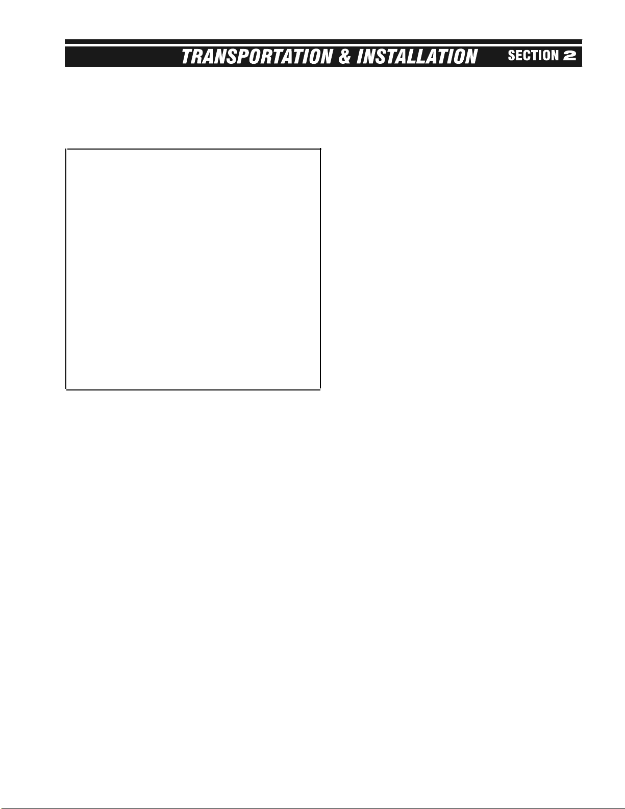
FUEL CONNECTION
LIQUID PROPANE (LP) DRYERS WITH INTERNAL
VAPORIZERS
LIQUID DRAW - The dryer is designed to operate on
liquid propane, with liquid draw from the supply tank.
A piping system is provided on the dryer, including
strainer, pressure relief valve, and manual shut-off
valve; a pressure regulator is provided on the fan-
heater unit, between the vaporizer and burner.
AMMONIA TANKS - Do not use propane supply tanks
which have previously contained ammonia or fertilizer
solutions. These substances are extremely corrosive
and damaging to fuel supply and burner parts.
OIL OR WATER IN TANKS - With liquid draw from the
supply tank, any water present in the tank may freeze
in the piping and controls in cold weather. To ensure
that tanks are free of moisture, the usual precaution is
to purge with methanol. Avoid tanks which may con-
tain an accumulation of oil or heavy hydrocarbons from
long use on a vapor withdrawal system.
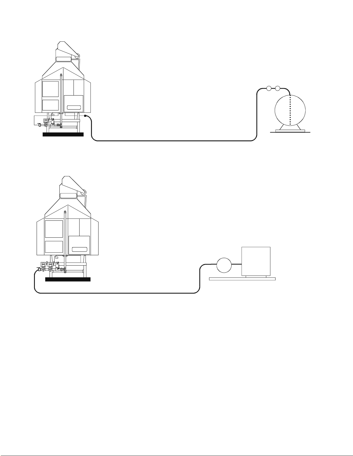
NATURAL GAS (NG)
GAS VOLUME AND PRESSURE - The dryer is
designed to operate on natural gas having a heat value
of about 1,000 BTU per cubic foot. The dryer is
equipped with a natural gas supply pipe system con-
nected to the heater solenoid valves. A regulated pres-
sure of 8 to 10 PSI must be provided at the connection
to the dryer, with gas available in sufficient volume to
maintain operating pressure.

8
USE A FLEXIBLE CONNECTION
HOSE DESIGNED FOR LP GAS.
SEE TABLE 2-1 FOR
RECOMMENDED LINE SIZE.
FUEL SUPPLY SYSTEM SHOULD
CONFORM WITH NATIONAL FIRE
PROTECTION ASSOCIATION STANDARDS.
CONSULT PROPANE SUPPLIER FOR
PROPER FITTINGS, CONNECTION
HOSE, AND SAFETY CONTROLS
REQUIRED TO MEET STANDARDS.
DO NOT USE A PRESSURE
REGULATOR AT THE SUPPLY TANK.
OPEN LP SHUT-OFF VALVES SLOWLY
TO PREVENT ACCIDENTAL CLOSING
OF EXCESS FLOW VALVES.
PROPANE SUPPLY
TANK. RECOMMENDED
MINIMUM OF 1,000 GALLONS
CONNECTED FOR LIQUID
DRAW.
LP CONNECTION
21SENS.DS4
PSC
ASC
C-2100B
C-2100B
SEE TABLE 2-1 FOR
RECOMMENDED LINE SIZE.
NATURAL GAS METER AND REGULATOR.
SEE TABLE 2-1 FOR REQUIRED PRESSURE
AND TYPICAL MAXIMUM FUEL FLOW RATES.
PSC
ASC
C-2100B
C-2100B
21SENS.DS4
NATURAL GAS CONNECTION
Fig. 2-1 Fuel hookup

ELECTRICAL POWER SUPPLY
POWER SUPPLY — An adequate power supply and
proper wiring are important factors for maximum per-
formance and long life of the dryer. Electrical service
must be of adequate size to prevent low volt age dam-
age to motors and control circuits. All dryers should be
field provided with a dependable equipment ground.
Electrical power supply should conform to local, state,
or provincial requirements.
NOTE: The dryer's power supply wiring should enter
the PSC Box Assembly on the right-hand side of the
box.
POWER SUPPLY DISCONNECT — A power supply
disconnect switch external to the Control Box is rec-
ommended for all dryer installation sites. This discon-
nect switch is to permit total power shutdown before
opening ASC dead front, as required for inspection and
service and should be located close to the dryer for
quick shutdown.
TRANSFORMERS WIRING VOLTAGE DROP —
Contact the service representative of the power suppli-
er, to advise of the additional load to be placed on the
line. Check on KVA rating of transformers, consider ing
total horsepower load. The power supply wiring, main
switch equipment, and transformers must be capable
of providing adequate motor starting and operating
voltage. Voltage drop during motor starting should not
exceed 14% of normal voltage, and running voltage
(after motor is at full speed) should be within 8% of nor-
mal voltage.
ELECTRICAL LOAD — Table 2-2 indicates the electri-
cal load in horsepower and full load current, for motors
on the dryer.
OVERLOAD RELAYS — If for some reason a particu-
lar relay needs adjustment, most overload relays are
adjustable within a safe operating range of 85% to
115% of normal load in amperes by an adjustment
knob on the relay.
CONNECTING AUXILIARY CONVEYORS (OPTIONAL)
Auxiliary load and unload motor controls are not sup-
plied as a standard part of the dryer control panel. A
signal contact is provided to control a separate auxil-
iary load conveyor motor starter dedicated to this func-
tion.
A. All auxiliary equipment must be powered from a source
outside the dryer. Each auxiliary motor must have a
separate contactor and overload protection device.
B. For automatic operation: use 110V contactor coils and
connect auxiliary LOADING coil to terminal 128 of the
ASC terminal block and a neutral of the coil to the
power panel neutral. Connect auxiliary UNLOADING
contacts (N.O.) of the aux-unload contactor to termi-
nals 82 and 47 of the ASC terminal block. With this
setup, the dryer's unload auger will not run unless the
aux-unload contactor is energized. For automatic shut-
down of take-away when a burner lockout shut-down
occurs, connect 110V unloading coil to terminal 47 of
the ASC terminal block and a neutral point. Refer to
control circuit wiring schematics.
9
Liquid
Propane
(LP)
Natural
Gas
(N)
Total Max Fuel Flow - Gal./Hr. 1
Recommended Liquid Line Size
Heater Orifice Drill Size
Max. Burner Pressure (PSI)
Pressure Regulator Setting (PSI)
Total Max Fuel Flow 1
(1000 Cubic Ft./Hr.)
Minimum Pressure at
Connection to Dryer (PSI)
Recommended Minimum Line
Size - 100' Distance
Burner Orifice Size (dia.)
Max. Burner Pressure (PSI)
Regulated Supply Pressure to
Dryer (PSI)
C-2130B
C-2130B C-2130B1
7.0
76
1/2"
0.500"
7.0
4.0 8.0
7.0
8
2"
0.625"
5.5
3.5-10 7-10
1. Maximum fuel flow rates listed assume full heat output for gas line sizing purposes. In normal operation the flow rates would
be considerably lower than indicated, due to actual setting used and cycling of heater.
2. Uses stainless steel octagonal type burner.
Maximum Heat Capacity (Million BTU/hr)
TABLE 2-1 FUEL SYSTEM RECOMMENDATIONS
C-2140B
C-2140B C-2140B1
9.0
98
1/2"
0.500"
11.5
6.0 12.5
9.0
10
2"
0.625"
9.0
5-10 10
C-2160B, C-2175B, &
C-21100B
C-2160B C-2160B1
12.0
130
3/4"
0.625"
9.0
5.0 10.0
12.0
10
2.5"
0.750"
7.0
5-10 10

10
C. When conveyor motors are powered from an external
source and they are connected for automatic opera-
tion, their overload relays (N.C. contacts) should be
connected in series and then connected into the dryer
safety circuit as shown in Fig. 8-6, SAFETY CIRCUIT
wiring diagram. It is recommended that these addi-
tional motor overload relays be added near the other
motor overload relays in the safety circuit.
BE SURE THAT DRYER ASSEMBLY HAS BEEN
COMPLETED ACCORDING TO C-2100B FIELD
ASSEMBLY INSTRUCTIONS, Bulletin C21BIN-01-2,
and THAT START-UP PROCEDURE IS FOLLOWED
AS OUTLINED IN THIS OPERATOR'S MANUAL
BEFORE OPERATING DRYER.
117
59
75
37.5
225
150
13
6.5
40
25
Horsepower
Full Load Current
(amps)
Max Running Load
(dryer only, amps)
Overload Setting
Circuit Breaker
Rating - amps
NOTE: Auxiliary load and unload motor controls are not supplied
as a standard part of the dryer control panel. A signal contact is
provided to control a separate auxiliary load conveyor motor
starter dedicated to this function.
IMPORTANT: This chart shows dryer running loads for the dryer
only and does not include the amperage necessary for auxiliary
equipment! On most new installations the additional aux. convey-
or motor load must be considered when sizing the power supply
system.
Voltage
3-PH - 230V
3-PH - 460V
3-PH - 230V
3-PH - 460V
3-PH - 230V
3-PH - 460V
3-PH - 230V
3-PH - 460V
3-PH - 230V
3-PH - 460V
Fan
30
30
76
38
Top
Auger
7.5
7.5
20
10
Bottom
Auger
5
5
13.2
6.6
Size
1/3 HP DC Control Amps / Volts
2.2A / 230VAC Motor Amps / Volts
1.6A / 180VDC
TABLE 2-2 ELECTRICAL LOAD, OVERLOAD
RELAYS, and CIRCUIT BREAKERS
20
10
40
25
C-2130B
155
78
100
50
300
150
20
10
50
25
Horsepower
Full Load Current
(amps)
Max Running Load
(dryer only, amps)
Overload Setting
Circuit Breaker
Rating - amps
Voltage
3-PH - 230V
3-PH - 460V
3-PH - 230V
3-PH - 460V
3-PH - 230V
3-PH - 460V
3-PH - 230V
3-PH - 460V
3-PH - 230V
3-PH - 460V
Fan
40
40
100
50
Top
Auger
10
10
26
13
Bottom
Auger
7.5
7.5
20
10
26
13
50
25
C-2140B
205
103
146
73
400
225
26
13
50
25
Horsepower
Full Load Current
(amps)
Max Running Load
(dryer only, amps)
Overload Setting
Circuit Breaker
Rating - amps
Voltage
3-PH - 230V
3-PH - 460V
3-PH - 230V
3-PH - 460V
3-PH - 230V
3-PH - 460V
3-PH - 230V
3-PH - 460V
3-PH - 230V
3-PH - 460V
Fan
60
60
146
73
Top
Auger
10
10
26
13
Bottom
Auger
10
10
26
13
26
13
50
25
C-2160B
240
120
A: 90
B: 90
90
400
250
26
13
50
25
Horsepower
Full Load Current
(amps)
Max Running Load
(dryer only, amps)
Overload Setting
Circuit Breaker
Rating - amps
Voltage
3-PH - 230V
3-PH - 460V
3-PH - 230V
3-PH - 460V
3-PH - 230V
3-PH - 460V
3-PH - 230V
3-PH - 460V
3-PH - 230V
3-PH - 460V
Fan
75
75
180
90
Top
Auger
10
10
26
13
Bottom
Auger
10
10
26
13
26
13
50
25
C-2175B
310
155
A: 116
B: 116
116
400
300
26
13
50
25
Horsepower
Full Load Current
(amps)
Max Running Load
(dryer only, amps)
Overload Setting
Circuit Breaker
Rating - amps
Voltage
3-PH - 230V
3-PH - 460V
3-PH - 230V
3-PH - 460V
3-PH - 230V
3-PH - 460V
3-PH - 230V
3-PH - 460V
3-PH - 230V
3-PH - 460V
Fan
100
100
234
117
Top
Auger
15
15
38
19
Bottom
Auger
10
10
26
13
38
19
63
32
C-21100B SCR MOTOR DATA

PRIMARY COMPONENTS
POWER DISCONNECT
The dryer is equipped with a power disconnect lever on
the front of the PSC control box. Note that a power
supply disconnect external to the dryer is also recom-
mended, as described under the Electrical Power
Supply heading in Section 2.
CONTROL START/STOP
With all dryer circuit breakers turned ON, the Main
Control circuit can be energized by first rotating the red
Stop switch clockwise until the button pops out to
enable the control circuit, and then pushing the green
START button. The green light on the START button
indicates that the control circuit is ON and that all safe-
ty switches are reset.
Push the red STOP button to stop the dryer control cir-
cuit. Note that this button remains locked in the OFF
position until rotated to enable the control start.
A warning HORN will sound when the STOP button is
enabled (pulled out), until the START button is pushed
and the safety circuit is energized to allow dryer opera-
tion.
FAN START/STOP
The Fan can be started by pushing the green START
FAN button. When the Fan is up to speed and air pres-
sure is proven, the green light on the START button will
glow. When this light is on, the purge cycle timer will
start.
Push the red STOP FAN button to stop Fan.
BURNER ON/OFF
Turning the Burner On/Off switch ON merely enables
burner ignition. Actual burner ignition requires proven
airflow, a purge time, and the Main/Safety Shutoff Valve
to be in the OPEN position. A purge time of approxi-
mately 15 seconds begins after the fan air pressure is
proven as indicated by the illumination of the Fan Start
button.
With BURNER switch ON and the purge cycle com-
pleted, the green BURNER ENABLED light will light for
5 to 15 seconds. During this time, the burner can be
ignited by opening the Main/Safety Gas Shutoff
Valve(s) (both valves must be opened on natural gas
units). Should the BURNER ENABLED light go off
before ignition takes place, the burner will lock out as
indicated by the red burner Lockout Indicator. The fire
protection timer can be reset after a short cool-off time
by pushing the green button on the Flame Safeguard
Control located inside the ASC control box. Ignition
can then be retried.
When ignition is completed, the green BURNER
ENABLED light will remain ON as long as a fire is
sensed. If the flame is lost, the red Burner Lockout
Light will come on and the FLAME SAFEGUARD con-
trol must be manually reset to reignite burner.
MAIN/SAFETY GAS SHUTOFF VALVE
VALVE OPERATION - This is an electrically energized,
manual reset type valve. The valve is equipped with an
electric solenoid which is energized only when the
dryer Burner Switch is turned ON.
The valve has a "free handle" lever which will not open
the valve to allow gas flow to the dryer until the Burner
Switch is turned ON. Only then will the lever engage to
allow the handle to be manually raised to the latched
position, thereby opening the valve. The valve will trip
closed instantly when its solenoid is de-energized; gas
flow will also stop when the lever is rotated to the
closed position.
An "open" and "shut" indicator is provided on the side
of the Main/Safety Shutoff valve. (An orange indicating
bar aligns itself with the words "open" or "shut.")
Note: For the burner to fire, the Main/Safety Gas
Shutoff Valve must be manually reset to OPEN and the
fan must be ON.
LOAD AUGER
The LOAD AUGER switch has three positions: ON,
OFF, and AUTO.
The ON position is recommended when initially filling
an empty dryer. With switch ON, the top auger will
operate, but the Load Timer is de-energized.
With the switch in either AUTO or ON, the top auger
automatically starts and stops, as required, to keep the
dryer full of grain.
The AUTO switch position is the normal setting and is
used to automatically stop the dryer when the wet grain
supply is exhausted. With switch in the AUTO position,
the Load Timer will be energized whenever the load
auger is operating. If the load auger and timer operate
continuously for a period longer than the timer setting,
the timer will automatically shut down the dryer and the
LOW GRAIN light will come on.
LOAD (Top Auger) TIMER
FUNCTION - The top auger loads the wet bin inter-
mittently, depending on when the paddle switch calls
for more grain. The Load Timer checks that the load
auger doesn't run beyond the normal time to fill the wet
grain holding bin. If, due to inadequate wet grain sup-
ply, the load auger runs longer than a normal refill time,
the Load Timer causes a dryer shutdown.
The Load Timer, located within the ASC control box, is
an automatic reset type timer. The amber LOW GRAIN
shutdown indicator will light whenever a shutdown is
caused by the Load Timer.
11

12
TIMER SETTING - To set the Load Timer, observe the
normal time required to fill the wet bin, then rotate the
front dial to set timer to the average refill time plus sev-
eral additional minutes.
NOTE: The Load Timer can be set to several time
ranges of operation. The timer is factory set in the 60-
minute range mode. With this arrangement, the no. 1
mark on the dial face equals 1/6 of the 60-minute
range or 10 minutes.
UNLOAD AUGER
The UNLOAD AUGER switch has two positions: OFF
or ON.
With switch in the ON position, the auger runs continu-
ously and the meter rolls are controlled by the
Unloading Switch position (Manual/Off/Auto).
With switch in the OFF position, the meter rolls and
auger are stopped.
The UNLOAD AUGER switch energizes the meter roll
safety circuit monitor. This monitor will cause a dryer
shutdown if meter roll rotation is not sensed for a peri-
od longer than three minutes and the METER ROLL
shutdown indicator will be energized.
DRYER OPERATOR LIGHT
LIGHT OPERATION - The dryer operator light is
designed to act as either a dryer monitor signal light, or
a night convenience light.
SWITCH POSITIONS - The three-position switch pro-
vides ON, OFF, or MONITOR operation. When the
switch is set ON, the light will stay energized even
when the dryer is shut down. When the switch is set to
MONITOR, the light will be ON only when the dryer is
operating.
NOTE: The light circuit is 115 volts and is intended for
100 watt bulb operation. Do not install an oversize light
bulb!
HOUR METER
The hour meter is useful in keeping track of seasonal
use of the dryer and determining when service is
required. The hour meter is non-resetting and accu-
mulates hours only when the fan is powered.
PLENUM TEMPERATURE CONTROL
Setting the Plenum Temperature:
A. Push the DISP button once and SP (set point) will be
displayed in the Lower LH corner. See Fig. 3-1.
B. Raise or lower SET POINT to the DESIRED plenum
temperature by pushing the arrowed buttons to
increase or decrease (set-point range is 0-250°F).
C. Push RESET to return to plenum temp display. A set
point should not be in the display. If display is inactive
for 60 seconds, it automatically returns to a plenum
temp display.
The PLENUM TEMP Controller will automatically begin
opening the gas control valve when a flame is proven
and will modulate the control valve to hold the Plenum
set point entered.
METER ROLL CONTROLS
UNLOADING SWITCH
Switch has three positions: MANUAL, OFF, and AUTO.
The UNLOAD AUGER switch must be ON in order for
the Unloading Switch to operate meter rolls. With
Unloading Switch in the MANUAL position, meter roll
speed is controlled by the MANUAL UNLOADING dial.
With switch in the AUTO position, meter rolls are con-
trolled automatically by the Moisture Control unit.
With the Unloading Switch set to Manual, the Moisture
Control can only display grain temperature, but cannot
control meter roll speed. With the Unloading Switch
OFF, the Moisture Control display is also off.
MANUAL UNLOADING DIAL
The Manual Unloading dial sets meter roll speed to a
constant unload rate. Set the desired % unload rate by
watching the Unloading Rate volt meter as the Manual
Unloading dial is adjusted. See Drying Time Tables in
Section 5 for suggested start-up settings.
UNLOAD RATE METER
The UNLOADING RATE volt meter monitors the DC
ARMATURE VOLTAGE on the SCR MOTOR driving
the meter rolls. This voltage represents the %
UNLOAD RATE of the dryer and should range from 7%
to 100% as the unload speed is changed. Be sure to
use the Unloading Rate volt meter as the primary indi-
cator of the % unload rate, as the Manual Unloading
dial setting will be close to but not as accurate as the
volt meter reading.
VARI-TROL MOISTURE CONTROL
Vari-Trol Moisture Control works on the principle that
grain moisture and grain temperature are closely relat-
ed. Monitoring grain temperature, combined with man-
ual testing of the grain's final moisture content, will
Honeywell
Alm
Out
PV
DISP RESET
SETPOINT
INDICATOR
CONTROLLER USED FOR
VARITROL & PLENUM TEMP CONTROLS
2100HNWL.DS4
DISPLAY
BUTTON
INCREASE /
DECREASE
BUTTONS
TEMP
INDICATOR
RESET
BUTTON
Fig. 3-1 Controller used for Vari-Trol and
Plenum Temp controls

allow the operator to determine the proper tempera-
ture/moisture relationship. Using the Moisture Control
temperature display on the ASC panel, the operator
can view the current grain temperature and set the
desired grain temperature (set point), in the manner
described as follows.
NOTE: As previously stated, with the Unloading Switch
set to Manual, the Moisture Control can only display
grain temperature, but cannot control meter roll speed.
With Unloading Switch set to OFF, the Moisture Control
display is also off.
SETTING TEMP
a. Push DISP (display) button once and current set point
will be displayed as indicated by the letters SP (set
point) in the lower LH corner. See Fig. 3-1.
b. Raise or lower set point to desired temperature by
pushing the triangle buttons to increase or to decrease
(set-point range is 0-200°F).
c. Push RESET to return to measured temperature. SP
will not be displayed. If display is inactive for 60 sec-
onds, it will automatically return to measured tempera-
ture display. If moisture control is turned off while in the
SP mode, the newly entered set point will be canceled.
OPERATING WITH AUTOMATIC MOISTURE CONTROL
1. See Drying Tables in Section 5 for initial drying times
and initial % Unload Rates. Then start the dryer on
manual control.
2. Measure discharged grain moisture. If adjustments are
required, change the Manual Control Dial as required;
allow dryer to operate for one grain pass before
rechecking moisture.
NOTE: Time (min.) for one grain pass is as follows:
For dry/cool: Grain pass = Drying Time x 1½
For full heat: Grain pass = Drying Time
where Drying Time is found in the Drying Tables.
3. After the grain discharge has been readjusted and sta-
bilized at desired moisture content, note the tempera-
ture on the Moisture Control and adjust the set point to
the temp noted. Be sure to push the Reset button after
entering a new set point before proceeding.
4. Move the Unloading Switch from MAN to OFF, then to
AUTO, pausing 5 to 6 seconds in the OFF position.
This pause is necessary for the Moisture Control to
reinitialize. If the Moisture Control has been correctly
reinitialized, first zero degrees and then the correct
grain temperature will display after the switch is set to
AUTO. Failure to wait for a complete reset can cause
a lengthy delay in the time the Moisture Control needs
to arrive at the correct meter roll speed. Also impor-
tant: DO NOT CHANGE THE MANUAL UNLOAD
RATE WHILE IN THE AUTO MODE.
5. The Moisture Control unit will begin automatically con-
trolling the meter roll speed to compensate for changes
in the grain input moisture by maintaining the set point
temperature entered.
6. If large changes in grain input moisture are encoun-
tered, repeat the setup procedure to establish a new
set point temperature.
7. When restarting a loaded dryer following a shutdown
period, the dryer should be operated in the MANUAL
mode, until the newly dried grain has passed the RTD
grain sensor (2/3 of the grain pass time) and the grain
temperature has stabilized, before switching to the
AUTOMATIC mode. The Moisture Control set point
should not require readjustment.
See Section 5, Dryer Operation, for moisture control
operating procedure.
METER ROLL MONITOR SYSTEM
Operation - The meter roll monitor system is designed
to provide automatic shutdown of the dryer if the meter
rolls fail to rotate due to obstructions, malfunction, or
failure to turn the meter roll selector switch ON. The
monitor system functions only when the unload auger
circuit is energized, as required for normal meter roll
operation. See Fig. 3-2.
The main monitor system components are briefly
described as follows:
Proximity — The Meter Roll Proximity switch is mount-
ed on the unload auger drive end of the dryer, on the
same side as the auger motor. This switch senses the
rotation of the meter rolls and sends an electrical signal
to the meter roll monitor in the ASC control box.
(See Fig. 3-2, 6-9 and General Control Circuit in
Section 8.) The light on the switch indicates LOAD ON
each time a rotation has been sensed.
The proper switch adjustment is 1/8” to 1/4” clearance
between Proximity switch head and the rotating target.
The Proximity switch is slotted to allow readjustment, if
required. When properly adjusted, the LOAD ON indi-
cator will light every time the target rotates near the
proximity switch.
Meter Roll Monitor — The meter roll rotation is moni-
tored by the solid state Meter Roll Monitor Relay in the
ASC control box. The monitor is active whenever the
Unload Auger switch is in the AUTO position. If the
Monitor fails to see a change (either opening or clos-
ing) in the Proximity Switch signal within three minutes,
the safety circuit will be broken and the dryer will auto-
matically shut down. The Monitor resets automatically
when the control start button is pushed.
13
Fig. 3-2 Meter roll monitor proxswitch.tif

14
SHUTDOWN FEATURES
SHUTDOWN INDICATORS
The C-2100B series dryers are equipped with a safety
circuit monitor which helps to locate the cause of a
dryer shutdown by energizing an indicator light.
When a safety shutdown occurs, the control circuit will
be disabled, the horn will sound, the Dryer Operator
Light (if set to monitor position) will go off, and the
appropriate shutdown indicator light will be energized.
The indicator will stay energized until the control stop
or start button is pushed. Be certain to check the indi-
cator lights before stopping the dryer control. If the
shutdown device requires manual resetting or has not
yet automatically reset (due to cool down time
required), the light will reappear when a control start is
attempted.
NOTES:
• If, during periods of troubleshooting, the horn
becomes an annoyance, it can be temporarily disabled
by pulling the fuse on the RH end of the terminal strip
in the upper part of the ASC control box (see Fig. 6-4).
The horn volume can be adjusted by turning the allen
screw located on the horn's case.
• NO indicator light will come ON if a motor overload
relay trips open. Also, note that the shutdown detector
unit is designed so that if a malfunction occurs within
the unit, such as a bad light or poor wiring connections,
it will not prevent the dryer from operating but will only
cause abnormal action of the indicator lights.
RESTARTING DRYER AFTER A SHUTDOWN
1. Investigate the cause of shutdown and perform any
necessary adjustments or corrections. For addi tional
information, refer to "Control Circuit Not Energized"
heading within Section 9. As a future reference, it may
be advisable to make a record of the cause, as indicat-
ed by the shutdown indicator.
NOTE: On rare occasions, several dryer safety
devices may act to interrupt the safety control circuit
simultaneously. If this occurs, the LOWEST NUMBER
INDICATOR LIGHT on the de tector will always take
priority, as the unit is built to indicate only one cause at
a time
2. Press the dryer START button. When the start button
is pressed, the dryer control light should come ON,
indicating that all safety devices have been reset and
the dryer is operational.
Following is a list of shutdown indicators. For the most
common shutdown causes, see Section 9,
Troubleshooting.
ADJUSTING DRYER AIRFLOW
C-2100B DRY/VACUUM COOL DRYERS
The fresh air louvers, located on the sides of the fan-
heater module, can be adjusted to balance the amount
of cooling air required. Opening the louvers wider will
reduce the amount of vacuum cooling and increase the
drying airflow rate. Closing the louvers will increase
the cooling airflow rate while reducing the amount of air
to the drying zone.
In general, the louvers should be adjusted to create 2
to 2½ inches of water column (wc) vacuum in the cool-
ing plenum. The louvers should be adjusted to approx-
imately 8% open. With the HR-2100B Heat Reclaimer
option, the louvers will be approximately 2% open.
NOTE: As the louvers are adjusted, both drying and
cooling capacities are affected. Higher static pressures
will increase cooling capacity, but decrease drying
capacity. Lower static pressures will increase drying
capacity but decrease cooling capacity. Also, the
unload rate can have an impact on the louver settings.
Lower unload rates can be operated at lower static
pressures since the grain is in the cooling section of the
dryer for longer time periods.
When drying crops wetter than 25% moisture, dryer
capacity may be improved by increasing the fresh air
louver opening. Monitor dry grain temperature for ade-
quate cooling when making final adjustments.
The louvers can be adjusted by moving the HFWL 1/2-
13 nuts located on the louver adjusting stud protruding
through the dryer floor panel on each side of the fan-
heater module. Fine adjustments can be made by
rotating the louver handle assembly. By moving the
louver handle assembly toward the center of the dryer,
the HFWL nut will pass through the keyhole slot in the
floor panel allowing the louvers to be quickly moved to
a closed position when not in use. When adjusting lou-
vers, it is best to open each side approximately the
same.
When dryer is shut off, the pressure gauge (located on
the right-hand side of the fan motor housing just to the
right of the ASC control box) should return to a zero
reading. Over time, however, the gauge may drift out
of calibration. If this occurs, refer to Section 7, Service,
for re-zeroing procedure.
SHUTDOWN INDICATOR LIGHTS - ASC PANEL
• METER ROLL MONITOR (auto resets immediately)
• LOW GRAIN (auto resets immediately)
• PLENUM HI-LIMIT (auto resets after cooling
• GRAIN HI-LIMIT (auto resets after cooling)
• BURNER LOCKOUT (reset manually by pressing Flame
Safeguard button after cooling)
UNMONITORED SAFETY SHUTDOWN DEVICES
• Unload auger overload relay
• Load auger overload relay
• Fan overload relay
• SCR overload relay
• Discharge shut-off switch
• Auxiliary load overload relay (optional)
• Auxiliary unload overload relay (optional)

RECLAIMER DAMPER (HR-2100B HEAT
RECLAIMER OPTION)
The reclaimer damper, used on C-2100B dryers
equipped with the HR-2100B series heat reclaimer,
must be adjusted to balance the reclaimed air from the
heat zone reclaiming duct to the fan inlet vacuum
plenum. The damper should be adjusted by opening
the rear reclaimer door and checking for a slight vacu-
um in the duct. If a positive pressure is noticed (air
flowing out the door), open the reclaimer damper slight-
ly. If a large vacuum is noticed (air flowing into the
duct), close the reclaimer damper slightly.
NOTE: Making an adjustment change in the fresh-air
louvers may require a slight reclaimer damper adjust-
ment.
HEAT RECLAIMER DOORS
The HR-2100B reclaimer is equipped with hinged
cleanout doors every two feet along the length of the
reclaimer duct. These doors can be opened for clean-
ing the dryer and reclaimer duct wall.
The dryer can also be operated with the reclaimer
doors in the OPEN position to allow reclaiming air to
escape when full reclaiming is not desired. In this situ-
ation, the reclaimer damper should be FULLY CLOSED
and the fresh-air louvers readjusted to give the desired
grain cooling required.
C-2100B1 SERIES FULL HEAT DRYERS
FRESH AIR LOUVERS
The fresh air louvers on the C-2100B1 series dryers
should be fully opened during drying operation.
On C-2100B1 series dryers equipped with HR-2100B1
series Heat Reclaimer, the louvers should be approxi-
mately 66% open, creating a slight vacuum in the fan
inlet plenum. This opening should be fine tuned by
watching the pressure on the hinged skirt doors. If the
doors are being blown outward by the dryer exhaust
15
BLOWER
BURNER
MOTOR
GRAIN COLUMNS
FRESH AIR LOUVER
REAR OUTER FLOOR PANEL
TOP VIEW
HEAT ZONE RECLAIMER DUCT
HR-2100B SERIES HEAT RECLAIMER RECLAIMER DAMPER
HR-2160B OPTIONAL HEAT RECLAIMER
RECLAIMER DAMPER
HR-2130B OR HR-2140B OPTIONAL RECLAIMER
PLENUM DIVIDER
CLEANOUT DOOR
GRAIN COLUMNS
VACUUM GUAGE
ASC
PSC
HINGED RECLAIMER
SIDE PANEL
HR-2100B1 SERIES
OPTION - FH RECLAIMER
21BAIR.DS4
C2100B1 SERIES FH OR
PRESSURE COOL
DRYERS ONLY -
VACUUM PLENUM
SIDE PANEL
PART NO 401-3994-1
C2100B SERIES VACUUM
COOL DRYERS ONLY
BLOWER PLENUM FLOOR PANEL
PART NO 401-3993-3
HINGED CLEANOUT DOOR
HR-2100B OPTION
Fig. 3-3 Heat reclaimer option

16
pressure, close the fresh air louvers slightly until they
stay in the closed position, indicating a slight vacuum in
the lower reclaiming duct. See Fig. 3-4.
The louvers can be adjusted by moving the HFWL 1/2-
13 nuts located on the lover adjusting stud protruding
through the dryer floor panel on each side of the fan-
heater module. Fine adjustments can be made by
rotating the louver handle assembly. By moving the
louver assembly toward the center of the dryer, the
HFWL nut will pass through the keyhole slot in the floor
panel, allowing the louvers to be quickly moved to a
closed position when not in use. When adjusting lou-
vers, it is best to open each side approximately the
same
REAR OUTER FLOOR PANEL
The rear outer floor panel should be removed from C-
2100B1 series dryers only when the HR-2100B1 series
reclaimer is used to allow air to flow from the lower
reclaimer to the fan inlet enclosure.
HINGED RECLAIMER SIDE PANELS (HR-2100B1 HEAT
RECLAIMER OPTION)
The hinged reclaimer side panels allow easy access to
the lower part of the dryer for cleaning. They can also
be opened to allow exhaust air to escape when
reclaiming is not desired. When operating under these
conditions, fully open the fresh air louvers.
C-2100B1 SERIES PRESSURE COOL DRYER
(WITH FH/PC-2100 OPTION)
FRESH AIR LOUVERS
The fresh air louvers on the C-2100B series pressure
cool dryers should always be adjusted to the full open
position. See Fig. 3-4.
RECLAIMERS
Exhaust air cannot be reclaimed when pressure cool-
ing.
Fig. 3-4 Airflow diagram

Before the dryer is filled with grain and placed into
actual drying operation, thoroughly inspect the unit
and check out the operation as described in the follow-
ing steps.
1. Set controls and switches as described in the following
chart:
CONTROL TEST FIRING SETTING
Burner Switch OFF
Load Auger switch OFF
Unload Auger Switch OFF
Unloading Switch OFF
Manual Unload Setting Adjust to minimum
Loading Timer 30 minutes
2. Inspect metering rolls and inside of dryer.
Open all metering roll access doors and all hinged fast-
trip clean-out doors and carefully inspect each com-
partment for any bolts, nuts or other foreign hardware
which may have dropped into these areas during dryer
installation and setup. Remove all material present to
prevent possible jamming of the meter rolls or bottom
auger and contamination of dried grain.
Check the inside of air plenum chambers and remove
all foreign materials.
3. Check Fan Belt tension and condition. Refer to Table
1-5 for proper belt tension.
4. Check plumbing for leaks.
Open the main fuel supply valve to allow fuel flow to the
electrically operated Main/Safety Gas Shut-off Valve.
On NG dryers, open the 2" hand valve and check for
leaks in the fuel supply plumbing and the dryer fuel
manifold up to the Main/Safety Shutoff Valve.
On LP dryers, open the 3/4" liquid valve and check for
leaks in the fuel supply plumbing and vaporizer plumb-
ing up to the liquid solenoid valve.
NOTE: Open the shutoff valve slowly to prevent acci-
dental closing of the excess-flow valve within supply
system.
Turn ON the Power Disconnect lever located on the
PSC Power Box. Using a jumper wire, temporarily
jump power from terminal #3 to terminal #36 on the
ASC terminal strip to power the liquid solenoid valve
open and pressurize the rest of the vaporizer plumbing.
Turn the electrical disconnect OFF and check the
vaporizer plumbing for leaks.
Proceed only after ALL fuel leaks have been corrected.
5. Turn ON the main power disconnect located on the
PSC Power Box.
6. Start dryer control circuit.
Turn the Control Stop switch to ENABLE the controls
and push the Control Start button. The green light on
the Control Start button should immediately light, indi-
cating the safety circuit and control circuit are ener-
gized to allow dryer operation.
7. Check conveyor motors rotation.
A. With the wet grain supply shut off, quickly bump
(jog) the Load Auger Switch to the ON position. The
top auger should rotate clockwise as viewed from the
drive end. Any wet grain auxiliary supply conveyors
connected to the dryer power terminals should also
start and rotate in the proper direction.
B. Quickly bump (jog) the Unload Auger Switch to the
ON position. The bottom auger drive motor pulley and
auger shaft should both rotate counterclockwise as
viewed from drive end. Any dry grain auxiliary convey-
ors connected to the dryer power terminals should also
start and rotate in the proper direction. See Fig. 6-9.
C. With the Unload Auger Switch ON, set the
Unloading Switch to MANUAL position and check the
direction of rotation. The RH metering roll shaft should
rotate counter clockwise as viewed from the rear end of
the dryer. See Fig. 6-10.
8. Check meter roll operation.
With Unloading Auger still operating, rotate the MANU-
AL UNLOADING control to increase meter roll speed
and check the metering roll drive mechanism for prop-
er operation throughout its full speed range.
The UNLOAD RATE should range from approximately
7% to 100%. Make sure all drive belts and chains are
properly tensioned and that all sections of the meter
rolls rotate properly and smoothly.
9. Check blower motor rotation.
Open the fresh air louvers on the left-hand side of the
fan-heater module. Jog the blower motor by pushing
the FAN START switch and then immediately push the
FAN OFF switch and observe the direction of the fan
rotation. The fan should rotate clockwise as viewed
from the drive shaft side.
NOTE: If all dryer motors run backward, they can eas-
ily be reversed by changing the dryer's power supply
connection. Auxiliary conveyors which have been field
connected may have to be reversed individually.
10. Check blower motor starting.
Start the blower motor and observe the number of sec-
onds required for the blower to reach FULL RPM. The
blower should reach full speed within 10 to 15 seconds
and the motor running current should be within accept-
able limits to the full-load amperage listed in the elec-
17

18
trical specifications of this manual. Check for a green
light on the fan start switch, indicating that the blower
pressure has been proven. On models equipped with
part-wind start, the delay timer should be set to 1 to 2
seconds.
NOTE: Pressure may not be adequate to activate the
pressure switch when testing an empty dryer.
Temporarily jump terminals 31 and 32 before proceed-
ing with burner test firing.
11. Burner test firing.
A. Set the Plenum temperature control to 150°F. The
plenum temperature should be reading approximately
ambient temperature at this time.
B. Check to see that the fuel supply hand valves are
on.
C. Preset Modulation Valve Linkage
Check to see that fuel modulating motor arm is starting
from a position near 12 o'clock and that the butterfly
valve linkage is in a nearly closed position (rotated to
the stop counter-clockwise). See Fig. 6-2.
D. Check Flame Guard Lockout
With the blower on, turn the Burner Switch to ON. The
green ENABLED light will come on when the purging
cycle is complete (approximately 15 seconds after
blower pressure has been proven). Do not operate the
safety shutoff valve at this time. In 5 to 15 seconds, the
burner LOCKOUT light will come on and the ENABLED
light will go out. Turn the burner switch OFF and reset
the flame guard lockout by pressing the RESET button
located on the Flame Safeguard control inside the ASC
control box.
E. Ignite Burner
Turn the burner switch ON. When the green ENABLED
light is observed, open the Main/Safety Gas Shutoff
valve. Ignition should occur, the fuel modulator motor
will begin opening the butterfly valve, fuel pressure
should be observed on the pressure gage downstream
of the butterfly valve, and the plenum temperature
should begin to rise.
F. Set Regulator
Observe the pressure on the gage mounted on the
Main/Safety Gas Shutoff valve upstream of the butter-
fly valve. This pressure should be regulated to the
pressures shown in Table 2-1, Fuel Specifications. Set
the regulator to the proper pressure.
NOTE: The regulator pressures specified in the charts
are for maximum BTU rates required. Under drying
conditions with moderate ambient temperatures, lower
than normal drying temperature, or on dryers equipped
with air recirculation, lower regulator settings may be
used.
G. Adjust Low Fire
The plenum temperature controller should stabilize on
the set point temperature after a short time of opera-
tion. Decrease the plenum set point to 100°F to cause
the controller to go to minimum fire position. Adjust the
linkage (rod length) on the butterfly valve to obtain a
1/2 to 1 PSI burner pressure and observe the fire
through the hole in the center of the rear access door.
The fire should appear evenly spread within the burner
baffles.
H. Check High Fire
Increase the plenum temperature controller to 150°F.
The controller should stabilize on the set point after a
short time. While the temperature is climbing, the mod-
ulation motor should drive the butterfly valve to an open
position. At this time, the regulated pressure gage
should be reading nearly the same pressure as the
burner pressure gage. If the burner gage is consider-
ably lower, the butterfly valve is not open enough and
the effective arm length on the modulator motor should
be increased. Make this adjustment when operating in
low fire. Reset low fire adjustment as well.
I. Check Ignition
Turn the burner switch to OFF and allow the modula-
tion motor to return to low fire. Turn the burner switch
ON and open the Main/Safety Gas Shutoff valve.
Verify that the low fire adjustment allows burner to
ignite quickly and reliably. Slightly increase minimum
gas pressure if ignition is slow.
J. Check Burner Control Circuit Shutdown
Turn the unload auger ON and set the Unloading
Switch to Manual. With the burner still operating, turn
fuel supply hand valve OFF. After the burner has
burned down the fuel in the lines, the flame guard con-
trol should go into lockout. This should cause the
unload auger OPERATING light to go off. Within three
minutes, the dryer safety circuit should cause a com-
plete dryer shutdown. Be sure to reset the burner
flame safeguard and open the fuel valves if dryer is to
be refired.
12. Check moisture control operation
A. Set all switches to the positions shown in step num-
ber 1.
B. Start the dryer control circuit, turn the unload auger
to ON, and set the Unloading Switch to MAN position.
Adjust the UNLOADING RATE to 30%.
C. The moisture controller should be reading approx-
imately the same as ambient temperature unless there
is still residual heat in the dryer from previous burner
operation. Set the Moisture Controller to match the
measured temperature displayed.
D. Set the Unloading Switch to AUTO, pausing a few
seconds in the OFF position. The unloading rate
should begin at the previously adjusted manual unload-
ing rate.
E. Increase the moisture controller set point approxi-
mately 30°F above the current measured temperature.
The unloading rate should drop to approximately 2/3 of
the manual unload rate, or 20%.
F. Decrease the moisture controller set point approxi-
mately 95°F below the measured temperature. The
unloading rate will increase to approximately twice the
manual unloading rate, or 60%.
This manual suits for next models
4
Table of contents
Other Farm Fans Farm Equipment manuals
Popular Farm Equipment manuals by other brands

New Holland
New Holland CX720 Repair manual

Ferrari Costruzioni Meccaniche
Ferrari Costruzioni Meccaniche FX Use and maintenance

ORGANIC TOOLS
ORGANIC TOOLS OBSTRAUPE SILVER FOX 04 Assembly and operating instrustions

breviglieri
breviglieri MG-4 Operating and maintenance manual

DK-TEC
DK-TEC HNEFG user manual

Hardi
Hardi KS Series Instruction book