Farm Fans FFI Silver King Series User manual

Silver King Series
Inline Centrifugal Fan
ICF-01-2
Copyright © 1998 ffi Corporation
Models:
CIL18
CIL24
CIL28
CONTENTS
Safety Precautions . . . . . . . .2
Warranty . . . . . . . . . . . . . . .2
Installation . . . . . . . . . . . . . .3
Dimensions . . . . . . . . . . . . .4
Operation . . . . . . . . . . . . . .5
Service . . . . . . . . . . . . . . . .6
Wiring Diagrams . . . . . . . . .7
Safety Decals . . . . . . . . . . .9
Operators Manual
ffi
Corporation / Farm Fans

2
Farm Fans warrants its products to be free of defects in
material and workmanship. The only obligation of the
manufacturer is to repair or replace products which
have been submitted and found to be defective within
24 months after installation. If so found defective, the
products will be repaired or replaced without charge,
this constituting and entirely fulfilling the warranty oblig-
ation. Farm Fans assumes no liability for expenses
incurred without written authorization; in no event shall
its liability include special or consequential damages or
exceed the selling price of the product.
This warranty does not cover products or parts which
have been damaged by negligent use, misuse, alter-
ation or accident. Some components supplied by man-
ufacturers are warranted separately by those suppliers.
This warranty is exclusive and in lieu of all other war-
ranties, expressed or implied. Farm Fans reserves the
right to make design or specification changes at any
time without any contingent obligation to purchasers of
products already sold.
All instructions, with the exception of those concerning
safety, shall be construed as recommendations only;
because of the many variable conditions in actual
installation, Farm Fans assumes no liability for results
arising from the use of such recommendations.
WARRANTY
SAFETY PRECAUTIONS
USE CAUTION IN THE OPERATION OF THIS
EQUIPMENT
The design and manufacture of this system is directed
toward operator safety. However, the very nature of any
system using high voltage electrical equipment and
rotation parts presents hazards to personnel which
cannot be completely safeguarded against without
interfering with efficient operation and reasonable
access to components.
Use extreme caution when working around rotating
parts which may start without warning when the system
is operating on "Automatic" control.
Continued safe dependable operation of equipment
relies, to a great degree, upon the operator. For a safe
and dependable system, follow the recommendations
within this manual, make it a practice to regularly
inspect the operation of the system for any unsafe con-
ditions or developing problems.
TAKE SPECIAL NOTE OF THE OPERATING PRE-
CAUTIONS BELOW BEFORE ATTEMPTING TO
OPERATE THE SYSTEM.
CAUTION: Guards, access doors and covers must be
securely fastened before operating this equipment.
A CAREFUL OPERATOR IS THE BEST INSURANCE
AGAINST AN ACCIDENT.
Look for this symbol to point out important safety pre-
cautions. It means ATTENTION!
1. Read and understand the operation manual before
attempting to operate the unit.
2. Keep ALL guards, access doors, covers, safety
decals and safety devices in place and securely fas-
tened. NEVER operate system while guards are
removed.
3. Keep all untrained personnel away from system com-
ponents and control panel at all times.
4. NEVER attempt to operate the unit by jumping or oth-
erwise bypassing any safety devices.
5. Always open the main power supply disconnect
switch and lock it in the open position with a padlock
when performing any service or maintenance work on
the fan unit or control box.
6. Lock out power before removing guards, access
doors, and covers.
7. Keep hands, feet and clothing away from all rotating
parts.
8. Electrical repairs should be performed by trained qual-
ified personnel only. Failure to follow safe electrical
procedures can result in serious injury.
9. If it should become necessary to perform checks on
system components or high voltage tests with "live"
circuits, be extremely careful and follow all estab-
lished safety practices.
Copyright © 1998 by ffi Corporation. All rights reserved. No part of this publication may be used or reproduced in any form or by any
means without prior permission. Failure to comply with this notice is a violation of United States copyright laws.

FOUNDATION
For proper operation of your ffi fan, the unit is to be
mounted on a level pad. The fan should not be
anchored to the pad but should be allowed to “float” on
the pad. The fan pad should be at the same elevation
as the floor of the bin or building.
FAN INSTALLATION
1. See dimension illustration for the physical size of the
fan. Use the dimensions shown to determine the posi-
tion of the fan when installed.
2. Rotate the fan wheel to be sure it revolves freely and
does not contact the housing.
3. Check all fasteners on the fan to make sure they are
tight (fasteners may loosen during shipping). If any
loose fasteners are found, check for proper clearance
and retighten.
4. Check all electrical connections that may have loosened
during shipping.
5. Make certain that all joints and seams around the lower
part of the bin are well sealed to prevent air leakage
from the air space under the perforated drying floor.
The connecting air duct must be reasonably airtight.
Air leakage wastes fan efficiency.
6. The connecting air duct or “transition duct” and con-
nector should be all metal construction, with a gradual
angle to the rectangular opening through the bin wall.
7. Avoid abrupt angles or any type of connecting air duct
that would restrict airflow. The cross-sectional area of
the connecting duct should gradually increase to about
1.5 times the fan area where it enters the air chamber
through the bin wall.
8. Keep the air entrance as clear as possible from
obstruction by floor supports.
9. Adequate exhaust air openings in the roof are
required to prevent any additional back pressure (2
to 3 times fan outlet cross-sectional area).
ELECTRICAL INSTALLATION
1. The electrical installation must be performed by a certi-
fied electrician, in accordance with the appropriate
national and local electrical codes. Any violation of
electrical wiring codes could jeopardize the ffi warran-
ty.
2. ffi Corporation recommends contacting your local
power company to advise them of the additional load to
be placed on their line. Only the power company rep-
resentative can ensure that their system is sized prop-
erly to provide adequate service to your facility and
new equipment.
3. Each fan motor must be supplied with an independent
power circuit, equipped with a fused disconnect switch.
Locate this switch near the unit, as the power should be
shut off before opening the control box cover, or per-
forming any service on the unit. NOTE: The fused dis-
connect is provided by the owner and MUST BE COR-
RECTLY SIZED AND CONNECTED TO ALLOW
PROPER MOTOR OPERATION.
UNITS WITHOUT CONTROLS - It is the customer's
responsibility to provide a fused disconnect and motor
overload protection. The disconnect and overload
device must be sized and connected correctly to allow
proper motor operation. Failure to provide these com-
ponents could cause severe motor damage and void
the manufactures warranty.
4. Be sure that the disconnect and the fan are well
grounded.
5. The following wires must be supplied to each fan.
Units without control transformers require a separate
neutral and earth ground connection.
1PH 230V . . . . . . . . . . . . . . . .L1, L2, N, G
3PH 230V . . . . . . . . . . . . . . . .L1, L2, L3, N, G
3PH 230V with optional
transformer kit . . . . . . . . . .L1, L2, L3, G
3PH 460V . . . . . . . . . . . . . . .L1, L2, L3, G
6. Use electrical conductors of adequate size.
Undersized wire can lead to voltage drop and cause
motor overheating and shortened life. Therefore, it is
necessary to know the distance from the unit to avail-
able transformer and the horsepower of your fan unit.
These two factors will determine the size of wire need-
ed for efficient operation. The full load current is listed
in Tables 1 and 2. The full load current is also stamped
on the motor nameplate.
7. The starter controls require 115VAC power to operate.
On 230V 3PH units, this power is supplied by L1 to
neutral.
WARNING! The voltage between L1 and N
must be 115VAC. Any other voltage may
cause severe damage to equipment.
Check this voltage before starting unit. If voltage is not
within 105-125VAC, check for proper voltage on L2 or
L3 and move to appropriate leg. If voltage is not
acceptable, install a 0.25 KVA step-down transformer
kit (part no. TRANS-230). (Note: Grounded B and
some open delta power supplies will require this trans-
former kit.)
INSTALLATION CHECK
When the fan is completely installed, the unit will need
to be checked for proper rotation. Provide power to the
fan controls and start the fan momentarily. Make sure
that the fan wheel rotation is in the direction that the
decal on the fan housing illustrates. If the decal is
missing, note that the wheel should operate clockwise
when viewed through the inlet guard. If the wheel is
rotating the wrong direction, have your electrician cor-
rect the wiring.
3
INSTALLATION

4
INLINE CENTRIFUGAL FAN DIMENSIONS
TABLE 1 ELECTRICAL SERVICE - SINGLE PHASE
115V Single Phase 230V Single Phase
MOTOR Full Load Overload Heater Full Load Overload Relay / Heater Element /
HP Amps Relay Element Amps Part Number Part Number
1.5-3.0 -- -- -- 14 27A / 056-1062-1 C16.3 / 056-1143-9
3-4.5 -- -- -- 20 27A / 056-1062-1 C22.8 / 056-1166-0
5-7 -- -- -- 35 45A / 056-1046-4 C30.3 / 056-1142-1
7.5-10 -- -- -- 42 45A / 056-1046-4 C33.0 / 056-1153-8
10-15 -- -- -- 55 90A / 056-1083-7 F56.7 / 056-1203-1

After initial installation and also prior to using the unit
each season, check the operation to ensure proper
functioning, adjustment, and reliability.
FAN OPERATION
1. Make certain that unit is properly installed and con-
nected, as described within the installation instructions.
All air passage joints and seams must be well-sealed.
2. With main power supply turned OFF, rotate the wheel
by hand to make certain it turns freely without contact-
ing the housing or inlet cone.
3. Open roof doors to allow airflow at all times when fan
is operating.
CAUTION: Fan pressures can overload bin roof or
walls causing structural damage or collapse. Bin
must be adequately ventilated and fans and screens
free of obstructions. Do not run fans if icing can occur
on screens.
4. Turn ON main power disconnect switch.
CAUTION: Make certain all guards and covers are
securely in place.
5. Press the fan START button and check the following:
A. Check direction of wheel rotation. THIS IS A VERY
IMPORTANT CHECK ON INITIAL START-UP OF 3-
PHASE MODELS. The wheel must rotate clockwise
when viewed through the inlet guard.
NOTE: 3-Phase motors may be reversed by inter-
changing any two power leads.
B. Check to make sure the wheel comes to full operat-
ing speed in less than 10 seconds. If there is any doubt
as to proper operation, check the current draw of the
motor. The motor amperage should not exceed the
maximum full load amps listed within Tables 1 and 2 or
motor nameplate.
FAN SHUT-DOWN
1. Press the fan STOP button on units equipped with
motor controls.
2. Shut off electrical power at main and at disconnect.
3. Close the roof openings and cover fan inlet to prevent
harmful back-draft air currents from passing through
the grain and to avoid grain infestation from rodents
and insects.
5
OPERATION
P R E S S U R E I N I N C H E S
Fan 0.00 1.00 2.00 3.00 4.00 5.00 6.00 7.00 8.00 9.00 10.00 11.00
Model A I R F L O W I N C F M
FFI CIL18-1 2700 2500 2300 2070 1900 1550 -- -- - -
FFI CIL18-4 4250 3950 3680 3360 3060 2625 -- -- - -
FFI CIL24-5 6360 6040 5720 5400 4980 4550 4020 3500 -- - -
FFI CIL24-10 7260 6890 6360 5900 5600 5200 4770 4450 3180 -- -
FFI CIL28-15 10190 9800 9400 9100 8600 8200 7600 7250 6550 5680 5000 3600
Airflow ratings were determined in accordance with AMCA test code Standard 210.
CCENTRIFUGAL INLINE FANS STATIC PRESSURE (INCHES)
& AIR FLOW RATINGS (CFM)
TABLE 2 ELECTRICAL SERVICE - THREE PHASE
230V Three Phase 460V Three Phase
MOTOR Full Load Overload Relay / Overload Full Load Overload Relay / Overload
HP Amps Part Number Setting Amps Part Number Setting
1.5-3.0 8.5 7-10A / 056-2022-4 8.5 4 4-6A / 056-1968-9 4
3-4.5 13 12-18A / 056-1944-0 13 6 5.5-8A / 056-1949-9 6
5-7 15 12-18A / 056-1944-0 16 7.5 7-10A / 056-2022-4 7.5
7.5-10 24 17-25A / 056-1943-2 25 12 9-13A / 056-1971-3 12
10-15 30 23-32A / 056-2079-4 32 15 12-18A / 056-1944-0 15

6
FAN WHEEL REMOVAL & INSTALLATION
The fan wheel is secured to the motor shaft by the use
of a taper-lock bushing, motor shaft key, and cap-
screws. The size, quantity, and torque of capscrews
required will depend on the model of the fan.
CAUTION: Although the taper-lock method of
retaining the wheel onto the motor shaft is very
simple and obvious, it is essential that the follow-
ing points be read carefully and fully understood, as
improper installation can result in serious or fatal injury
caused by a loose, fast flying wheel.
THREADED BUSHING HOLES: The threaded holes
within the bushing are provided for disassembly pur-
poses only. Do not attempt to use these holes for
reassembly, as they will not allow the parts to become
locked onto the shaft, thereby causing an extremely
hazardous operating condition.
CLEARANCE HOLES: When reassembling parts, the
capscrews must be installed through the UNTAPPED
CLEARANCE HOLES to cause the wheel to be pulled
forward onto the tapered bushing, thus locking the
parts securely onto the motor shaft. Refer to text for
assembly details.
REMOVAL
1. LOCK-OUT THE MAIN POWER SUPPLY and remove
the fan guard and inlet cone.
2. Remove the three capscrews from the clearance holes
in taper-lock bushing. Inspect for thread damage and
set aside for later reinstallation (do not use these bolts
for step 3, bushing removal).
3. Install two Grade 5 (or better) capscrews into the
THREADED HOLES in the bushing and turn them in by
hand until they bottom against the front surface of the
wheel. These capscrews should not be used for
reassembly, as some thread distortion could occur dur-
ing the removal operation. Grade 5 screws are marked
with three 120° spokes on the head and are more
durable than low strength unmarked bolts.
NOTE: DO NOT ATTEMPT TO USE LOW STRENGTH
(UNMARKED) BOLTS TO REMOVE THE BUSHING,
AS THE BOLTS MAY BREAK OFF.
4. Block wheel to prevent it from turning, and GRADUAL-
LY TURN IN THE CAPSCREWS (up to 1/4 turn at
time), until the wheel breaks loose from the bushing
and motor shaft. Carefully remove bushing and wheel.
With the wheel free from the bushing, a wheel puller
can be used to pull the bushing off of motor shaft, if
required. Reattach bushing onto wheel to prevent the
loss of parts and also to maintain the original alignment
of bushing to wheel. Inspect wheel and bushing at this
time, looking for any cracks, thread or bolt damage,
warpage, etc. Consult your dealer or the factory for
any questions concerning damage.
INSTALLATION
1. Carefully clean motor shaft, key, bushing and bore of
wheel. MAKE SURE MAIN POWER IS LOCKED OUT,
and that shaft and key are completely free of rust and
burrs. Do NOT lubricate the bushing or capscrews.
CHECK AND MAKE SURE ALL MOTOR MOUNT
BOLTS ARE PROPERLY TIGHTENED.
Before installing the wheel, check the following: (1) All
foreign material should be removed from the wheel. (2)
Carefully inspect the wheel weldment and hub casting
for damage, cracks, or other defects. Contact the fac-
tory if there is any question regarding the structural
integrity of the wheel.
2. Slide wheel over motor shaft and locate it against the
motor.
3. Align the keyway in the bushing with the key and SLIDE
bushing onto motor shaft. Do not attempt to drive the
bushing onto the shaft, as it may damage the motor
bearings.
4. Rotate the bushing and wheel so their key slots are in
line and loosely attach the wheel to the bushing.
MAKE SURE THE CAPSCREWS ARE INSERTED
INTO THE UNTHREADED CLEARANCE HOLES IN
THE BUSHING. Refer to previous CAUTION note.
Locate the bushing so it is approximately flush with the
end of motor shaft.
Make certain that the proper capscrews are used for
reassembly and no damage has occurred to these
screws during disassembly! Use only the special type
bolts supplied with the original wheel.
5. Install inlet cone, checking clearance between fan
wheel and inlet cone. Shift the location of inlet cone as
required to center it in relation to the fan wheel, provid-
ing equal clearance completely around the fan wheel.
Tighten inlet cone bolts.
6. Slide the wheel forward onto the taper-lock bushing
and turn the capscrews in by hand as far as possible.
NOTE: The bushing must be located far enough for-
ward so the distance from the inside of the backplate of
the wheel weldment to the closest edge of the inlet
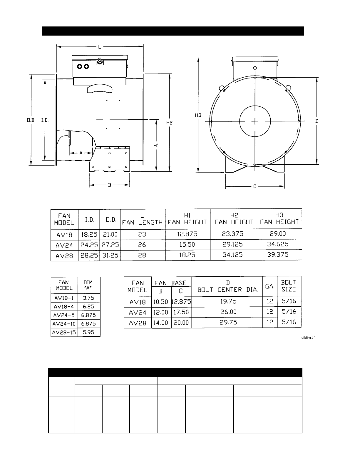
cone is equal to the dimension shown as ‘A’ in the Fan
Dimension Chart. Add approximately 1/8” to this
dimension to allow the wheel to be pulled toward the
inlet during tightening.
7. Use an INCH-POUNDS torque wrench and GRADU-
ALLY TIGHTEN the three capscrews (1/4 turn at a
time) until the taper bushing becomes fully seated.
Refer to the following chart for recommended capscrew
tightening torques. DO NOT EXCESSIVELY OVER-
TIGHTEN THE BUSHING.
SERVICE
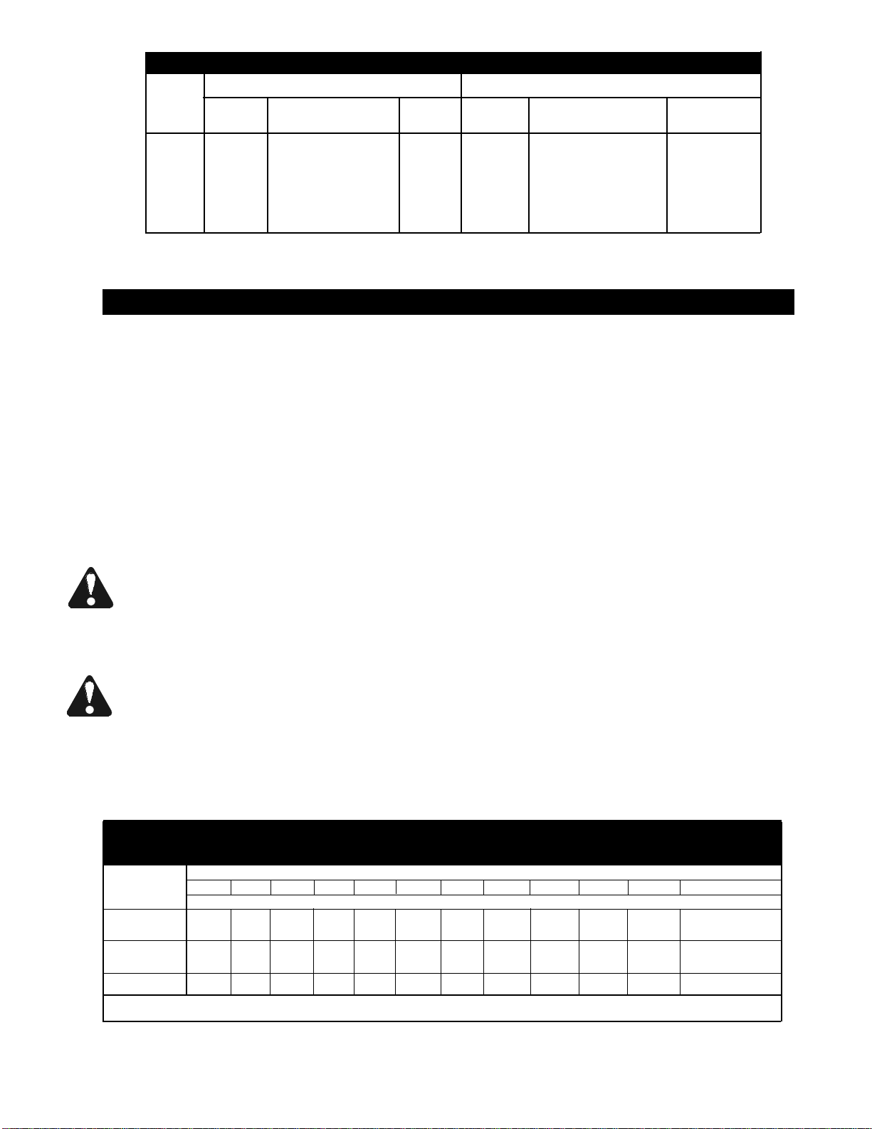
Browning Taper-Lock Bushing Bolt Tightening Torques
Bushing Size Hex Bolt Size Torque (Inch-Lbs.)
P 5/16-18x1-1/4 192

7
CAUTION: Do not attempt to pull the flange of the
bushing flush with the wheel hub. A clearance of from
1/8" to 1/4" must be maintained between bushing
flange and wheel hub surface.
8. Turn wheel by hand and check it for freedom of rotation
and uniform clearance around inlet cone before rein-
stalling the fan guard.
FAN MOTOR REMOVAL & INSTALLATION
In the event of motor failure, remove the motor, as
described, and take it to the nearest Authorized
Service Station. AUTHORIZED SERVICE STATIONS
ARE THE ONLY PLACES THAT CAN PROVIDE
MOTOR WARRANTY. Motor service and repair at
other places will be at owner’s expense.
If service station determines motor failure to be caused
by faulty material or workmanship, repair will be under
warranty when within the warranty period. Motor fail-
ure because of external causes will result in a charge
to the owner for repair.
1. Make certain power is shut off and locked out, then
remove fan guard, inlet cone, and wheel as outlined
earlier.
2. Open motor junction box cover and disconnect the
motor lead wires from within the box.
NOTE: Tag, or otherwise identify wires for ease of
reassembly.
3. Remove motor mount bolts. If there are any shims
between the motor and its base, note their locations so
they can be properly installed during reassembly.
4. Disconnect the motor end of the motor conduit, if
required, then carefully pull conduit and wires through
hole in the motor junction box. Remove motor. If motor
requires service, take it to an Authorized Service
Station.
5. To reinstall motor, slide onto motor mount and replace
shims (if required) between motor and mount.
Reinstall motor mount bolts and washers, and fully
tighten them at this time.
Reinstall conduit and wires and carefully remake all
electrical wiring connections.
NOTE: Make sure to install and tighten the wheel in
accordance with earlier instructions.
WIRING DIAGRAMS
Fig. 1 - Fan control box wiring diagram, 230V 1 phase

8
Fig. 2 - Fan control box wiring diagram, 230V 3 phase
Fig. 3 - Fan control box wiring diagram, 460V / 575V 3 phase

9
SAFETY DECALS
Safety decals should be read and understood by
all people in the grain handling area.
If a decal is damaged or missing, contact:
ffi Corporation
5900 Elmwood Ave.
Indianapolis, IN 46203
IMPORTANT
THIS UNIT IS WIRED FOR
230 VOLT, 1-PHASE
POWER SUPPLY
(Typical for 230V 1 phase models)

Copyright © 1998 ffi Corporation
5900 Elmwood Ave.
Indianapolis, Indiana 46203
7-29-98
This manual suits for next models
8
Table of contents
Other Farm Fans Farm Equipment manuals