Oil Burner Installation and
Operation Instructions
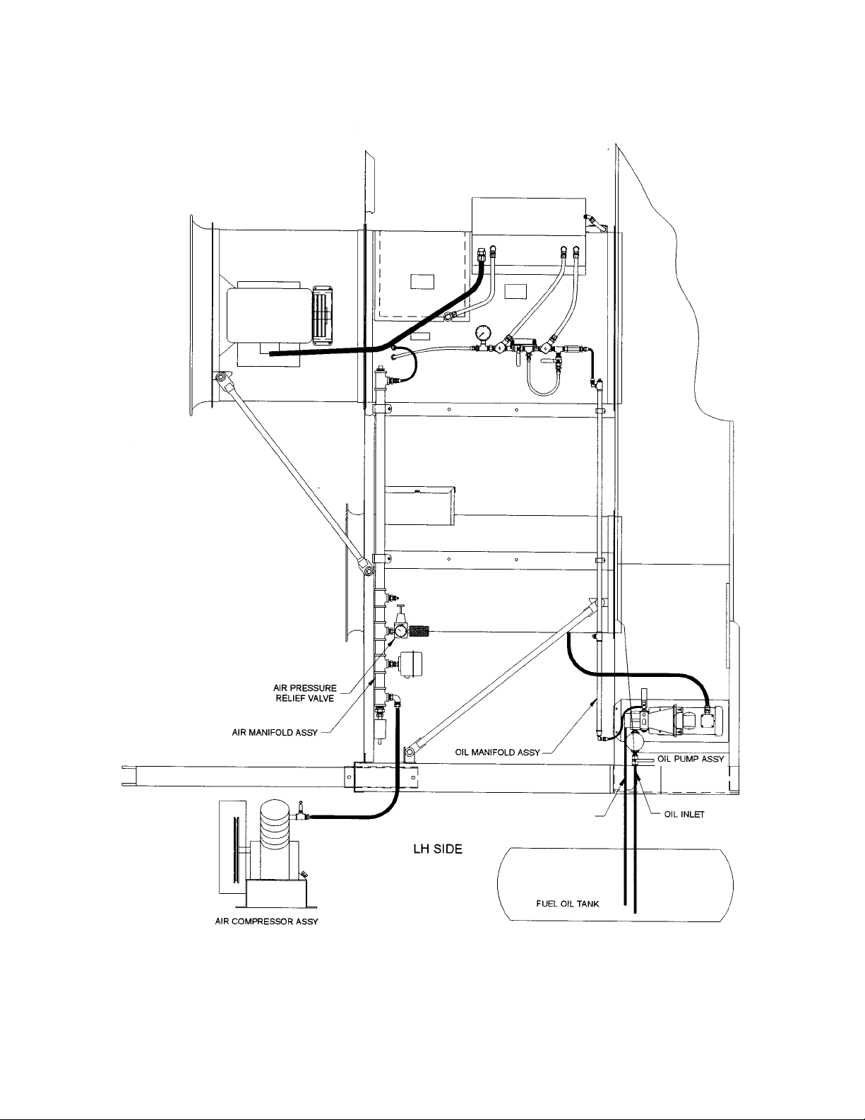
Compressor Assembly
• Locate the compressor in a clean
operating area away from the dryer. Locate
inside a shelter when possible.
• Fill compressor with oil supplied before
starting. See operators manual for compres-
sor.
• Do NOT install a shutoff valve on the com-
pressor inlet, outlet or line to the manifold.
• Check for correct rotation of compressor on
startup.
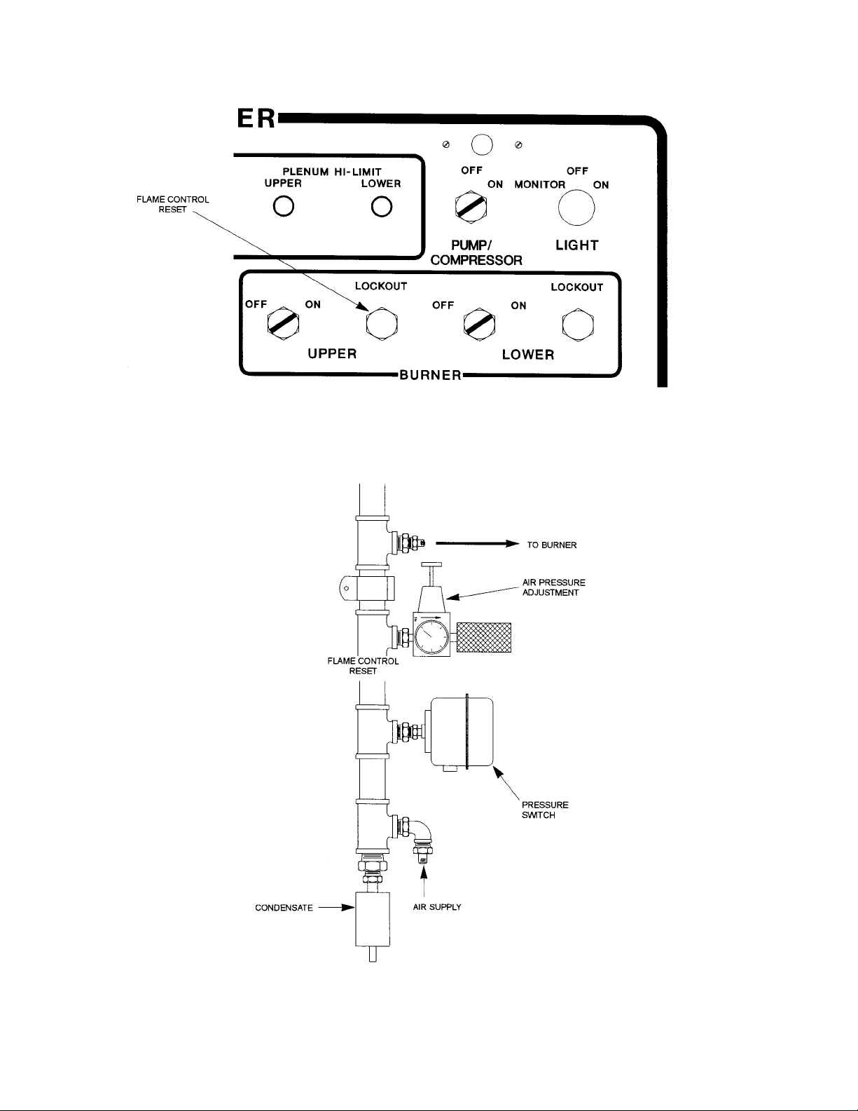
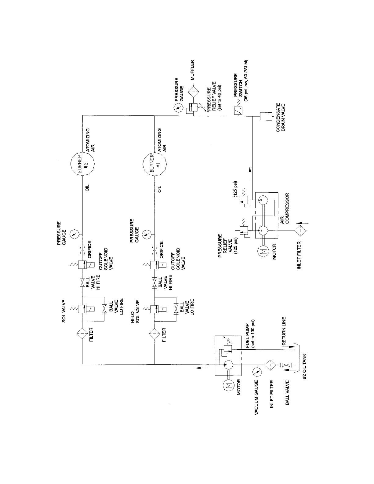
Air Manifold Assembly
• Mount manifold assy to dryer per attached
drawings. Mount manifold with condensate
drain pointing down.
• Connect manifold outlet to burner with
1/2 inch hose supplied.
• Connect manifold to compressor using a
1/2 inch hose. 50 feet have been supplied
• Do NOT install a shutoff valve on the com-
pressor inlet or outlet or lines to the tank.
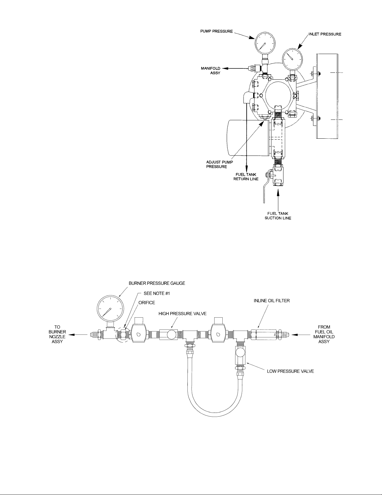
Oil Pump Assembly
• Install the oil pump assy to the LH front
body supports as shown in attached drawing.
• Connect the pump outlet to the oil manifold.
• Connect the oil manifold to the burner
plumbing assy using 1/4 inch hose supplied.
• Connect a suction line from the tank to the
pump. Line must be adequately sized so that
inlet suction does not exceed 17" hg.
Minimum size is 1/2 inch diameter.
• Connect a return line from the pump to the
tank. Use a minimum of 3/8 inch diameter
line.
• Check for correct rotation on startup. CCW
as view from shaft end of pump or fan end of
motor.
Burner Test Fire
1. Check rotation of compressor by bumping the
pump/compressor switch. Compressor should
rotate CW as viewed from the shaft end of com-
pressor.
2. Check rotation of pump. Pump should run
CCW as view from the shaft end of pump or fan
end of motor.
3. Open the suction and return line valves going
4
to the oil tank. With compressor circuit breaker
off, turn pump switch ON and check for pressure
on outlet gauge. Pressure should read 100 psi.
Adjust pump pressure as required. Check pres-
sure on pump inlet. Inlet pressure should be less
than 17 inches of Hg.
4. Turn on the compressor circuit breaker and
turn pump switch ON. Compressor should begin
building pressure in tank up to 45-50 psi. This
may take 10-15 seconds. Adjust relief valve on
air manifold as required to achieve the 45-50 psi.
Pressure must be in a range between 35 and 60
psi in order to fire the burner.
5. With the high fire valve OFF, turn the burner
switch to the ON position. Following a 30 second
purge period, the burner should attempt to ignite
for 4 seconds and then lockout. The red lockout
light will come on. The dryer will shut down after
a 2-3 minutes unless the flame control is reset or
the burner switch is turned OFF. The dryer shut-
down time can be adjusted by resetting the 3TR
timer located in the ASC box behind the control
front panel.
6. Reset the flame controller by pressing the red
lockout switch. The dryer must be powered, the
pump/compressor switch ON and the burner
switch ON in order to reset the flame control.
When the flame controller is reset (red lockout
light off), it will begin a 30 second purge period
and then try to reignite unless the burner switch is
turned OFF. Turn the burner switch off at this
time.
7. Turn the high fire valve approximately 1/3 on
and the low fire valve approximately 1/3 on. With
pump/compressor and fan motors on, turn the
burner switch to ON. Burner should light immedi-
ately following a 30 second purge period. The
amber light on the burner switch will indicate that
the flame has been proven. Check that the oil
pressure on the burner is in the correct range.
8. Observe fire through the hole in the dryer
access door. Check the quality of the flame
through the normal operating range of pressures
by using the high fire valve to change firing rates.
Typically, no atomizing air adjustment is needed
over the full range of firing rates. The lowest fire