Fast Lokal-200PC Parts list manual

1 Technical Description Lokal-200PC
1.1 Overview
laptop with in-built accummulator
USB connection correlator box
internal power supply laptop (if the
device has been supplied by F.A.S.T.)
BNC aerial connection
reset key for correlator box
external power supply/charging 12 volts
LED 12v power supply, external (lit red
when in operation)
plug-in connector for Bluetooth dongle
(dongle available as an accessory)
radio reception indicator LEDs (LED
channel colour A red, B yellow, C blue)
channel selection switch for volume (internal loudspeaker
or headphones)
Position I left: channel A or B
Position 0 central: off
Position II right: channel B or C
volume regulator for internal loudspeaker or headphones
6.3mm jack plug, headphones
connection for the transmitter of radio headphones
(radio headphones available as an accessory)
LED 12 volts power supply, internal accummulator (LED
red, flashes when voltage has fallen below 12 volts)
LED correlator box ON / OFF (LED red, is illuminated as
soon as the programme starts the box)
ON key (to switch on the correlator box in the Bluetooth
operation mode)
Illustration 1-1: Lokal-200PC overview

- 2 -
1.2 Scope of delivery
1x unit correlator case, contains:
- correlator box
- receiver channel A
- receiver channel B
- receiver AZ logger
1x unit 12 volt accummulator charger
1x unit 12 volt power supply cable
3x units radio antenna
2x units sensor with cable
2x units MB-4 measurement boxes
1x unit MB-4 accummulator charger
Optional accessories:
1x unit Dell ATG laptop
1x unit 100-240 volt charger
1x unit 12 volt charger (integrated in the
case)
1x unit Bluetooth dongle
1x channel C (additional, third channel,
with receiver and measurement box)
Illustration 1-2: Scope of delivery

- 3 -
1.3 Description
The Lokal 200 PC is supplied in an ABS case which consists of the following components. A central
component of the Lokal 200 PC is the laptop (Illustration 1-3, point 1) with the correlator programme to
control the correlator box and to process the measurement values received. Normally, the correlator box,
which receives the measurement signals from the measurement boxes, is firmly installed inside the case.
Only the USB connection cable (Illustration 1-3, point 2) is visible and has to be connected to the laptop
inside the case. If the laptop has not been supplied by F.A.S.T., please make sure that your laptop meets the
system requirements as listed in Chapter 1.3.5.
Illustration 1-3: Lokal-200PC
Another component integrated in the case is the control panel as can be seen in Illustration 1-3, point 3.
This control panel hosts additional control elements and operating controls which are described in detail in
Chapter 1.3.1. The plug-in connectors as can be seen under point 4 (see Illustration 1-3) to connect the
aerial and for power supply purposes are described in Chapter 1.3.2.
1.3.1 Control panel
If the Lokal 200 PC is connected to a vehicle and operated with the 12 volt power cable, the red LED as
described under point 1 (Illustration 1-4) is lit permanently. If, however, no power cable has been
connected and the correlator is operator by means of accummulators, the LED as shown under point 8 is
lit red. If the voltage for the correlator box drops below operating voltage, this LED (Illustration 1-4, point

- 4 -
8) starts flashing. Both LEDs, however, indicate only the voltage status of the correlator box
accummulators. The charging status of the laptop accummulator is indicated in the task bar on the display of
the laptop.
If wireless communication between the laptop and the correlator box is desired, you can establish such
wireless communication by means of the optional Bluetooth dongle (see Chapter 1.3.4). In order to establish
wireless communication, detach the USB connection cable (Illustration 1-3, point 2) from the laptop.
Then connect the Bluetooth dongle to the interface as shown in Illustration 1-4, point 2. As soon as the
Bluetooth mode has been activated on the laptop, the correlator box can be switched on through the key
(Illustration 1-4, point 10). Now the red LED as shown under point 9 is lit, and the correlator box is
ready for communication via the Bluetooth interface.
Illustration 1-4: Control panel
Point 3 in Illustration 1-4 shows the so-called Squelch indicator. This indicator visualises the availability
of radio signals transmitted by the measurement boxes as soon as the correlator programme has been started
on the laptop. When the red measurement box for channel A has been switched on, the first LED is lit red.
As soon as the blue measurement box with the sensor for channel B has been switched on, the second LED
is lit blue, and the third LED is lit yellow when a measurement box with channel C has been activated.
According to the selection of the channels in the correlator programme, only two LEDs are lit at the same
time. If a measurement box is activated and the corresponding LED is not lit, please check the aerials of the
measurement boxes and the aerial of the correlator (see Illustration 1-5, point 1), as well as the selected
channel(s) in the correlator programme,
The radio signals can be received and listened to through headphones to be connected to the jack as shown
under point 6 (Illustration 1-4). In order to listen to the signals with the headphones, just select the
corresponding channel with the channel selection knob as shown under point 4. If the knob is in the
central position, no channel has been selected and neither the internal loudspeakers nor the headphones issue
a tone. If the channel selection knob is turned left to position 1, either signals of channel A or signals of
channel B can be listened to. The settings in the correlator programme determine which channel can be
heard. Position 2 (right) lets you select channel B or channel C for rendering purposes. The signals are
normally rendered through the internal loudpseaker which is installed under the laptop. As soon as the
headphones have been plugged into the jack as shown under point 6, the correlator box automatically

- 5 -
switches to headphones and de-activates the internal loudspeaker. The volume for the loudspeaker and for
the headphones respectively is controlled through the regulator as shown under point 5.
The jack as shown under point 7 (Illustration 1-4) is to provide the connection to the transmitter of radio
headphones, which are available as an accessory.
1.3.2 Plug-in connector
On the right-hand side of the case (see Illustration 1-3, point 4) you will find the connections and keys as
shown in Illustration 1-5. Point 1 shows the BNC connection for the aerial. The aerial of the correlator has
to be fixed here. F.A.S.T. supplies an aerial ex works (art. no. 5437D) with BNC connection and a 90° BNC
angle (art. no. 5441D) so that the aerial can be arranged orthogonally to the ground.
Illustration 1-5: Connections
Point 2 in Illustration 1-5 shows the reset key of the correlator box. If any errors or interferences occur
during the measurement process which are due to malfunctions of the correlator box, the device can be reset
by pressing the reset key. In order to do so, just disconnect all external power supply from the jack as shown
in Illustration 1-5 under point 3; we recommend also to switch off the laptop. Then press the reset key for
5 seconds and reboot the system.
Point 3 shows the jack for the power supply. Here both the charger and the 12 volts power supply can be
connected to the device. As the power supply for the entire case is slightly more complex, the power supply
for the case is described below separately.
1.3.3 Power supply
The correlator can be operated in two ways concerning power supply. One option is operation with
accummulators, the other option is power supply through external sources. For the latter, the 12 volts power
cable as shown in Illustration 1-6 is used. The 12 volts plug marked with point 1 is plugged into the
lighter of the particular vehicle, and the plug marked with point 2 is plugged into the corresponding jack
(see Illustration 1-5, point 3) at the correlator case. If the device is operated through the power cable, all
components, i.e. both the laptop (if supplied by F.A.S.T.) and the corralator box, are supplied with power,
and the corresponding LED on the control panel is lit (see Illustration 1-4, point 1) indicating that the
device is supplied with energy through the power cable. If this particular LED is not lit, the vehicle probably
supplies insufficent voltage. In this case, you may have to start the engine of the vehicle in order to generate
sufficient voltage.

- 6 -
Illustration 1-6: 12V power cable
If the correlator is operated through the power cable, the accummulator is also charged at the same time.
This means that both the accummulator of the correlator box and the accummulator of the laptop (if supplied
by F.A.S.T.) are charged while the device is being operated.
Another mode of operation is the accummulator-based operation of the device, i.e. both the laptop and the
correlator box are supplied with power through the in-built accummulators. This operation mode is indicated
by the accummulator LED (see Illustration 1-4, point 8) on the control panel. As the laptop and the
correlator box are equipped with two separate accummulators, these two accummulators can be exhausted at
different points of time. If the laptop accummulator has run out of power, a message will occur on the
display irrespective of the programme currently used on the laptop. If the accummulator of the correlator
box has run out of power, this will be indicated through the correlator programme only, i.e. the correlator
programme has to be activated and operational so that the operator can receive the message concerning low
accummulator voltage.
When the accummulators are exhausted, they need to be re-charged either by connecting the 12 volts power
cable to the case or by applying the mains cables (part of the delivery). The advantage of the 12 volts power
cable is that both the correlator box and also the laptop are charged. The disadvantage is that re-charging the
accummulators of the correlator box takes a while and can thus not be recommended. Another, quicker
option is using the chargers. However, please keep in mind that, when using the chargers, the charger for the
correlator box (see Illustration 1-7) re-charges only the accummulator of the correlator box and not also the
accummulator of the laptop. The same happens when re-charging the accummulator of the laptop: only the
accummulator of the laptop is re-charged, but not the accummulator of the correlator box.
The power cables for the laptop and for the correlator box differ in shape and are equipped with different
plug-in connectors. In Illustration 1-7, the power cable for the correlator box is illustrated. The plug as
shown under point 4 in Illustration 1-7 has to be inserted into the jack on the right-hand side of the
correlator case as shown under point 3 in Illustration 1-5. The 100-240 volts mains cable can be
connected to a socket at point 5 (Illustration 1-7).

- 7 -
Illustration 1-7: Ansmann accummulator charger
When all cables of the power supply unit have been connected, the charger starts re-charging. The first
process is a 10-second test phase of the accummulator. This test is indicated through the red LED (see
Illustration 1-7, point 1), which flashes for 10 seconds after all cables have been connected. As soon as
the accummulator is being re-charged without any problems, the red LED is lit permanently. If the flashing
of the LED does not turn into a permanent light after 10 seconds, the accummulator is probably defective
and you should contact your dealer. When the accummulator has been fully charged, the red LED goes out
and the green LED as shown in Illustration 1-7 under point 2 is lit permanently. The accummulator of the
correlator box has been fully re-charged, and the charger can now be disconnected from the case. Point 3
in Illustration 1-7 shows the discharge key of the charger. This key is to discharge the accummulator of the
correlator box, which is necessary in exceptional cases to maintain the accummulator. Please keep in mind
that this charger re-charges only the accummulator of the correlator box in the case and not also the
accummulator of the laptop.
In order to re-charge the accummulator of the laptop, please use the 100-240 volts power cable supplied
separately. Connect the plug as shown under point 2 (see Illustration 1-8) to the jack on the rear side of
the laptop (see Illustration 1-3, point 5). Please note that you have to disconnect the 12 volts power supply of
the case from the laptop beforehand. The green Power LED marked with point 1 (Illustration 1-8) is lit as
soon as the power cable has connected the power supply unit (Illustration 1-8, point 3) to the mains. The
laptop itself indicates whether or not the accummulator has been fully charged. An LED with an
accummulator symbol is located either on the right or on the left of the cover (depending on model). This
LED is lit or flashes during the entire charging process. As soon as the accummulator has been fully re-
charged, this LED goes out.
Illustration 1-8: 230V laptop power supply unit
- 8 -
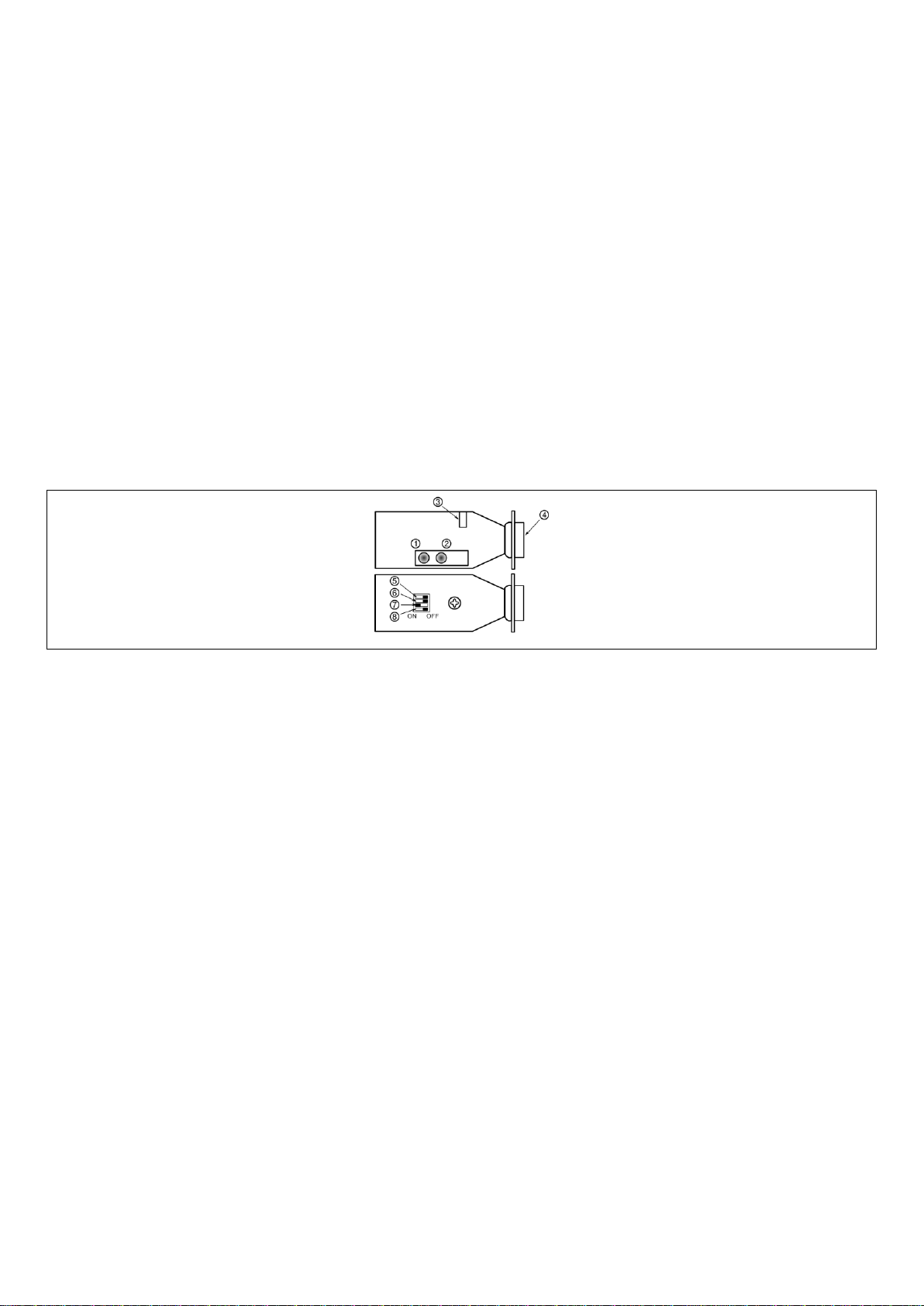
1.3.4 Bluetooth dongle
The Bluetooth dongle, which is available as an optional accessory (art. no. 9330D), is a Class-1 module and
communicates on a frequency of 2.4 GHz. The Bluetooth dongle (subsequently referred to as “module“) is
compatible with Bluetooth specification 1.2 and capable of communicating with the laptops supplied by
F.A.S.T., which are als equipped with a Bluetooth module.
The graphic below show the upper and the lower side of the module and its control and indication elements.
Point 1 in the graphic shows the green status LED, which indicates the status of the module. When the
module is being configurated, the green LED flashes 10 times per second. When the module is searching for
another device or when it is idle, the green LED flashes just once per second. If a connection could be
established, the green LED is lit permanently. The orange LED as shown under point 2 indicates the
status of the communication connection, i.e. if data is being transmitted or received, the orange LED starts
flashing.
Illustration 1-9: Bluetooth dongle
Point 3 in Illustration 1-9 shows the jack for external power supply. In general, 4 - 9 volts DC can be
applied to this jack. Please make sure that the positive voltage has been applied to the central pin of the jack,
and earth has been applied to the outside. If the power supply is 5 volts, the module requires a maximum of
300mA. If, however, you do not operate the module in combination with a F.A.S.T. correlator, the module
has to be supplied with power through the RS-232 connector (see also Illustration 1-9, point 4), i.e. no
external power supply is required.
Additional parameters of the module can be changed through the Dip switches (point 5 - point 8).
The switch marked with point 5 is to change the transmission rate (baud rate). The module allows
transmission rates of 115,200 baud and 9,600 baud. If the switch is switched to the left position, i.e. to ON,
9,600 baud are used for data transmission. If the switch is set to the right position, as can be seen in
Illustration 1-9, a baud rate of 115,200 is applied. The 115,200 baud rate is the standard recommended by
F.A.S.T. and should be applied. The communication parameters data bits, stop bits and parity
cannot be changed. The module uses 8 data bits, 1 stop bit, and no parity as communication parameters for a
connection.

- 9 -
The switch marked with point 6 activates the Master mode if the switch position is ON (left position). This
means that a module which operates in the Master mode controls communication. As the correlator
programme, i.e. the laptop, controls communication, the switch may remain at the OFF position, as can be
seen in Illustration 1-9. It is necessary to set the switch under point 7 to the left to ON (see Illustration 1-9)
to make the module change into the so-called Slave mode. The Slave mode allows control of the module
through the laptop. In order to reset the module to the ex works settings, use the switch as shown under
point 8. Set the switch to the ON position and apply power to the module, either externally or through the
plug-in connector (point 4). Then move the switch twice between ON and OFF. The module now resets to
the ex works settings. For regular operation with the correlator programme, the switch should be set to OFF.
1.3.5 System requirements for the correlator programme
The case containing the correlator box can also be purchased from F.A.S.T. GmbH without a laptop. In this
case, however, the following hardware-related requirements of the correlator programme should be met by
your own laptop:
Pentium or compatible CPU with 1 GHz or higher
1 GB RAM
Hard disc storage unit with 69.8 MB of available storage capacity
USB connection
CD/DVD drive
VGA / SVGA graphics card featuring a minimum resolution of 800 x 600 pixels
Mouse and keyboard
The installation of the correlator software requires the prior installation of any of the system softwares listed
below, including the necessary Service Pack, on your own device. If the software is installed on any other
system software, the programme may refuse booting.
Windows 2000 / Service Pack 4 --> 32bit
Windows XP / Service Pack 3 --> 32bit and 64bit
Windows Vista / Service Pack 1 --> 32bit and 64bit
Windows 7 / Service Pack 1 --> 32bit and 64bit
Table of contents
Other Fast Measuring Instrument manuals


Popular Measuring Instrument manuals by other brands

Parker
Parker PFM1 Series Installation and operation manual

Piusi
Piusi K24 Use and maintenance manual

Aichi Tokei Denki
Aichi Tokei Denki AS Series Handling manual

Turner Designs
Turner Designs AquaFluor manual

DMP Electronics
DMP Electronics 1301 Series Installation sheet

Enerpac
Enerpac EDI62 Series instruction manual


TempSen
TempSen Tempod quick guide

PRECISION DIGITAL
PRECISION DIGITAL Sabre Series Technical specifications

GPI
GPI LM-200 owner's manual

Endress+Hauser
Endress+Hauser Liquiline System CAT860 operating instructions

IFM Electronic
IFM Electronic OW installation instructions

Tektronix
Tektronix RSA3408A Service manual