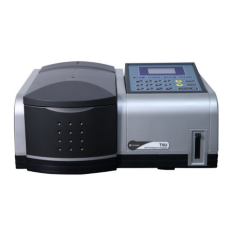
PERSEE PF7 User manual

1

Instruction manual
2
Contents
Chapter 1 Preface...................................................................................................... 1
1.1 Purpose............................................................................................................ 1
1.2 Principle............................................................................................................ 1
1.3 Structure........................................................................................................... 2
1.4 Main Features .................................................................................................. 3
1.4.1 Special pneumatic flow system .............................................................. 3
1.4.2 Double beam optical system.................................................................. 3
1.4.3 New Design gas-liquid separator ........................................................... 3
1.4.4 Efficient electronic Peltier....................................................................... 3
1.4.5 Pre-aligned lamp assemblies................................................................. 3
1.4.6 Scientific structural design...................................................................... 4
1.5 Specifications................................................................................................... 4
1.5.1 Performance........................................................................................... 4
1.5.2 Key Parts List......................................................................................... 4
1.5.3 Optional Accessories.............................................................................. 5
1.5.4 Optional Accessory Information.............................................................. 5
Chapter 2 Installation and Acceptance.......................................................................... 6
2.1 Lab requirements ............................................................................................. 6
2.1.1 Lab environment conditions: .................................................................. 6
2.1.2 Equipment requirements for the lab....................................................... 6
2.1.3 Gas Source Requirements..................................................................... 7
2.1.4 Power Supply Requirements.................................................................. 7
2.3 Installation........................................................................................................ 8
2.3.1. Connecting the computer system:...................................................... 8
2.3.2. Connecting with the PC system. ........................................................... 9
2.3.3 PF7 installation....................................................................................... 9
2.4 Acceptance......................................................................................................11
2.5 Testing method................................................................................................12
2.5.1 Test Conditions......................................................................................12
2.5.2 Repeatability (Relative Standard Deviation /RSD)..............................12
2.5.3 Detection Limit (DL) and Correlation Coefficient (R) .............................13
Chapter 3 Software Installation ....................................................................................14
3.1 PC Configuration.............................................................................................14
3.2 Installation.......................................................................................................14
3.3 The File System ..............................................................................................15
Chapter 4 AFWin Software Introduction .......................................................................16
4.1 Login ...............................................................................................................16
4.2 Initialization......................................................................................................16
4.3 Main Operating Interface.................................................................................17

Instruction manual
3
Chapter 5 AFWin Functions..........................................................................................18
5.1 Parameter settings..........................................................................................18
5.1.1 Instrument Control.................................................................................18
5.1.2 Sampling and measurement settings....................................................20
5.2.2 Standard Sample Concentration ...........................................................21
5.2.3 Sample Settings....................................................................................24
5.2 Sample Measurement .....................................................................................28
5.3.1 Measurement........................................................................................28
5.2.2 Save result............................................................................................29
5.2.3 Print result.............................................................................................29
5.3.4 Print preview .........................................................................................30
5.3.5 Right key menu in chart.........................................................................30
5.3 Calibration Curve.............................................................................................31
5.4 Testing result...................................................................................................32
5.5 User management...........................................................................................34
5.6 Set communication port...................................................................................35
5.7 Scanning .........................................................................................................35
Chapter 6 Analysis Conditions......................................................................................37
6.1 Arsenic (As).....................................................................................................37
6.2 Antimony (Sb)..................................................................................................38
6.3 Bismuth (Bi).....................................................................................................39
6.4 Mercury (Hg) ...................................................................................................41
6.5 Selenium (Se)..................................................................................................42
6.6 Tellurium (Te)...................................................................................................43
6.7 Tin (Sn)............................................................................................................45
6.8 Germanium (Ge) .............................................................................................46
6.9 Lead (Pb).........................................................................................................47
6.10 Zinc (Zn)........................................................................................................48
6.11 Cadmium (Cd)...............................................................................................49
Chapter 7 Notice of Storage andTransportation...........................................................51
Chapter 8 Daily Care and Maintenance........................................................................52
8.1 Daily care ........................................................................................................52
8.2 Troubleshooting...............................................................................................52
8.2.1 Tools......................................................................................................52
8.2.2 Communication failed............................................................................52
8.2.3 The problem of software........................................................................53
8.2.4 The problem of element lamp................................................................54
8.2.5 The problem of the testing.....................................................................54
8.2.6 Injection needle error of auto-sampler...................................................55
8.2.7 PC.........................................................................................................56
Appendix 1 Replacement of furnacefilament................................................................57
Appendix 2 After sales service .....................................................................................58

Instruction manual
1
Chapter 1 Preface
The Atomic Fluorescence Spectrophotometer is an excellent element analysis instrument
whichhas the advantages of atomic absorption spectrophotometer and atomic emission
spectrophotometer but overcomes their shortages in techniques. The instrument has good
accuracy, high sensitivity, simple structure, small volume and easy operation. It is designed
to test elements that could easily form hydride, gaseous constituents or deoxidizes to atomic
smoke. It is dedicated to the analysis of Arsenic(As), Mercury(Hg), Cadmium(Cd),
Germanium(Ge), Selenium(Se), Lead(Pb), Bismuth(Bi), Tellurium(Ti), Tin(Sn), Zinc(Zn),
Antimony(Sb) elements.
1.1 Purpose
The Atomic Fluorescence Spectrophotometer can be widely used in many industries, such
asenvironmental, food, pharmaceutics, water supply and drainage, cosmetics, soil and
fertilizer,clinical, agricultural products, geologic investigation, metallurgy, teaching and
research.
1.2 Principle
Principle: as shown in figure 1-1, The Gas source provides a constant pressure environment
for a constant liquid supply and solenoid valve control. The gas pressure takes up the
sample (in sample loop) and the KBH4 (in reaction bottle) into the gas liquid separator which
reacts and produces hydride gas (or atomic vapor). Hydride gas enters the atomizer and is
atomized, producing fluorescence light. The detector receives and tests intensity of the
fluorescence light which then transmits a signal to the processor. The processed result is
seen at the software on the PC system.
The instrument measures characteristics of the radiation exposure in the measured
elements of atomic vapor, around the electronic ground state atoms that are excited to be
high-energy state. Because the high-energy electronic state of the atoms become unstable,
they return to a low energy state, The external radiation is measured by Fluorescence which
is used for the quantitative analysis. The fluorescence intensity and the concentration of
elements following the relations: In the formula:
If=ΦI0(I-e-KλLN)
If ---------atomic fluorescence intensity;
Φ---------atomic fluorescence quantum efficiency;
I0---------Source radiation intense
Kλ--------Peak absorption in wavelengthλ;
L----------Light-absorption;

Instruction manual
2
N---------Units within the length of the ground state atoms
Fig. 1.1 Principle of PF7
1.3 Structure
The PF7 basic instrument information is shown in figure 1-2:
Figure 1-2 Sketch photo of PF7

Instruction manual
3
1.4 Main Features
1.4.1 Special pneumatic flow system
Argon is used as a driving source to achieve the automatic sampling, quantitative, discharge
functions with no need for maintenance. The pneumatic flow system is used instead of a
sipper pump system to avoid ripple caused by sipper pump and sampling errors caused by
tube deformation. The material of the carrier tube and reducer tube is FEP which has
excellent chemical stability and has a much longer life. The pneumatic sequential injection
system is used for the auto dilution, on-line washing of the sampling system which avoids
sample residue and high-concentration samples contamination. This helps to guarantee the
reliability of analytical measurement. The fully enclosed reagent bottles reduce the
decomposition rate of the reducer and guarantees the stability of long-term measurements.
1.4.2 Double beam optical system
The unique double beam optical design achieves time-share sample signal and reference
signal collection by one detector, and overcomes the influence on the results by the
temperature drift of the detector in a single beam instrument and has a significant correction
for lamp drift.
1.4.3 New Design gas-liquid separator
A magnetic stirring hydride generator changes the way the reaction is produced of existing
atomic fluorescence injection systems. The simplified flow structure of the atomic
fluorescence has the sample and reducer solutions inflow directly into the gas-liquid
separator via a three-way valve. The magnetic stirring forms an increased plume, thus
making the sample and reducer mixing more complete, and the reaction more intense. This
effectively improves the efficiency of the hydride’s outflow, transmission and reproducibility
of the analytical results.
1.4.4 Efficient electronic Peltier
The Peltier is used as a condensing device and offers direct contact cooling for the
gas-liquid separator, minimizing the water content of the hydride. This greatly reduces the
signal scattering interference and quenching which improves the detection sensitivity,
1.4.5 Pre-aligned lamp assemblies
The well-designed integrated pre-aligned element lamp with built-in electrical cable offers
automatic recognition, hot plug functionality and plug and play. The lamps are pre-aligned to
give consistency of the beam.

Instruction manual
4
1.4.6 Scientific structural design
Harmful gas exhaust is emitted via the exhaust hood. Due to the sealed design the
emissions are vastly reduced. The relatively high density harmful elements are absorbed by
a special reagent bag minimizing harmful gas inhalation. A fully enclosed waste bottle avoids
volatile of acid and waste gas, reducing environmental pollution and laboratory personnel
injuries. Inward optical design avoids ultraviolet light damage to personnel.
1.5 Specifications
1.5.1 Performance
The instrument should be allowed to warm up for > 30 minutes
Table 1.1 Specifications of PF7
Performance
specification
Stability
Drift ≤1.5%
Noise ≤1.5%
Reproducibility (RSD)
≤1.0%
Detection Limit (D.L.)
≤ 0.01 ng/mL ( Hg ≤ 0.001ng/ml )
Correlation coefficient (r)
≥ 0.999
Channel interference
±2%
Instrument
parameters
Optical system
Double beam
Communication interface
RS232, CAN
PC system
WINDOWSXP,WIN7,WIN8
Power
AC(100~240)V,50/60Hz,300W
All specifications above for As, Sb, Bi
Detection limit for Hg ≤0.001ng/ml
1.5.2 Key Parts List
Table 1-2
No.
Part No.
Name
1
A1701-02-01-03-00DQ
As lamp assembly
2
A1701-02-01-13-00DQ
Sb lamp assembly
3
A1701-02-01-09-00DQ
Bi lamp assembly
4
A1701-02-01-04-00DQ
Hg lamp assembly
5
A1701-06-05-00DQ
Main board
6
DH0200715401
PMT R7145

Instruction manual
5
Table 1-3
No.
Part No.
Name
1
A1701-04-10
Gas-liquid separator
2
S1201-04-01-00
Sampling tube assembly
3
9601-02-08-02-09
Resistance wire
4
9601-29-02-07
Target
5
A1701-13-00
Reagent bottle assembly
6
9601-02-08-02-15
Quartz tube
7
DK 1225330501
Fuse (5×20-3A)
8
A1701-29-02-01-01-00
As lamp package
9
A1701-29-02-01-10-00
Sb lamp package
10
A1701-29-02-01-11-00
Bi lamp package
11
A1701-29-02-01-02-00
Hg lamp package
12
A1701-14-02
Three Way Mixer
13
0987-05-000
987 Adapter
14
A1701-14-15-00
Waste bottle
1.5.3 Optional Accessories
Table 1-4
No.
Name
1
Speciation analysis accessories SA420 (isocratic orgradient)
2
AS420 Auto-sampler
3
WTM7 trace Hg in water analysis accessory
4
TGU7 Exhaust treatment accessory
5
MIU7 Micro-volume Syringe accessory
6
Fingerprint identification
7
Humidor Meter accessory
8
Laser Bar Code Reader
9
Bar code printer
1.5.4 Optional Accessory Information
Please contact your local dealer or Persee Analytics Inc. directly for information about our
optional accessories.

Instruction manual
6
Chapter 2 Installation and Acceptance
2.1 Lab requirements
2.1.1 Lab environment conditions:
The lab should be located away from strong electromagnetic interferences, strong light
source,strong vibrating equipment. The instrument should also be kept from influences of
direct sunshine,smoke dust, dirty air current and vapor. The AFS lab should be separated
from any chemical treatment room so as to avoid acid erosion. The lab should always be
kept clean with a correct temperature (at 15-35°C) and humidity (below 75% relative
humidity).
2.1.2 Equipment requirements for the lab
The laboratory bench should be large enough to install the PF7 instrument, Auto
Sampler and Speciation Accessory (if required), at a recommended height of 0.75 meters; it
should be stable and solid with a flat surface.
Around the bench, a space at least half a meter should be left to facilitate the operation
and maintenance.
The bench and instrument should be positioned out of direct sunlight, close to electricity
and gas connections.
Size and Weights of Instruments and Accessories:
Instrument
Length
Width
Height
Weight
AF402
610mm
595mm
450mm
35Kg
Auto Sampler
420mm
320mm
320mm
20Kg
SpeciationAccessory
600mm
560mm
415mm
40Kg
Efficient fume extraction should be installed in the laboratory to remove any fumes
generated by the instrument. See figure 2.1.
Note: Without adequate extraction, potentially toxic vapour could build up in the
laboratory. Always use an efficient fume extraction system when operating the instrument.

Instruction manual
7
A suitable extraction system should be fitted as Figure 2-1 above
2.1.3 Gas Source Requirements
It is the responsibility of the user to ensure that the gas installation conforms to the local
safety regulations.
The Argon gas, when configured with the AFS system, should have a purity of 99.99%.
Thesupply pressure should be set using a gas regulator. Aspecial gas cylinder storage room
is needed and a gas on-off valve in the laboratory should be installed.
The gas pressure should be set to 40psi / 2.8bar
2.1.4 Power Supply Requirements
The instrument and its accessories use a 220v AC (+/-10%) 50/60Hz power supply with
standard mains plugs, so a standard switchboard arrangement can be used. The power
supply should be free from noise and have a good earth connection. If the supply is outside
the requirements, a stabilized power supply unit can be used but must be rated higher than
1.5KW.
Please note: The main unit of the AFS, Auto Sampler and Accessories should all be
connected to the same electrical phase
Preparations before installation
1. Items check: unpack the instrument; check item by item against the packing list to
see if the main unit, accessories, parts, spare parts and the operation manual are
complete. Please check if there is any damage to the appearance of the instrument.
If there is a problem, please contact your local distributor.
2. Please read the operation manual carefully to familiarize yourself with the operating
principles and structure of the instrument.
3. Prepare the power supply, the fuel gas tubing, the waste fluid collector and the

Instruction manual
8
element lamps.
2.3 Installation
This chapter is for the installation engineer, and a reference only for the user.
2.3.1. Connecting the computer system:
The computer system comprises of a main frame, a display, a keyboard and a printer.
Connect the keyboard, the display and the printer to the respective interfaces on the
computer mainframe. Then connect the printer power cord at the back of the printer to the
220V power supply source. One end of the power cord for computer is connected to the
power supply socket at the back of the computer mainframe and the other end connected to
the 220V power supply source. The communication port 1 of the computer connects to the
RS232 communication port at theAF-402..
Fig: 2-3 connection of computer

Instruction manual
9
2.3.2. Connecting with the PC system.
Fig: 2-4 Signal connection diag.
1. F (3.15A): Fuse, AC220V/50Hz Power socket.
2. COM1: Communication port with PC.
3. USB: Communication port with PC.
4. COM2: Connect with the corresponding COM port of Speciation accessories.
5. CAN: Connect with the corresponding CAN port of Auto Sampler.
6. Accessory: Connect to the other accessories, like Micro Hg accessories, Micro
Syringe accessories and so on.
7. Waste: Connect to the waste level sensor.
8. Solution: Connect to the corresponding port of Reagent bottle assembly.
9. Temp. & Humidity: Socket for temperature sensor and humidity sensor.
10. Ar-IN: Argon inlet, connect to the argon cylinder regulator.
11. Ar-OUT: Connect to the Reagent bottle assembly.
12. Wash Liquid: Connect to the Wash bottle of Reagent bottle assembly (Green
connector).
13. Reductant: Connect to the reductant bottle of Reagent bottle assembly (Blue
connector).
14. Carrier: Connect to the Carrier liquid bottle of Reagent bottle assembly (Pink
Connector).
2.3.3 PF7 installation
According to Installation requirements, position the instrument on the table, connect
power, gas circuit, and flow path.

Instruction manual
10
•Connect main unit with auto-sampler, as shown in Fig.2-5
There is a power socket at back of the main unit and the auto-sampler. One end of the
power cable should connect with the power socket on the instrument and the other end
should connect with the mains power supply.
Fig.2-5 Power Connection of main unit and auto-sampler
•Flow path and gas circuit connection
Gas circuit connection of PF7 reagent bottles assembly (Fig. 2-6) is shown in Fig 2-7,
according to Test Method requirement, load required solutions.
For auto-sampler connection, please refer to AS420 Auto-sampler Operating manual.
Fig. 2-6 Reagent bottles Assembly

Instruction manual
11
Fig. 2-7 Flow path and gas circuit connection
•Pre-aligned lamp installation, is shown in Fig. 2-8
Plug Pre-aligned lamp in corresponding lamp socket, after start-up, set the lamp current
In the AFWin software.
Fig. 2-8 Element lamp installation
2.4 Acceptance
After installation, the instrument can be adjusted and accepted. But before acceptance,

Instruction manual
12
the operator must read the instruction manual carefully to get familiar with the operation and
acceptance method.
The following provides the testing methods for the specifications:
2.5 Testing method
2.5.1 Test Conditions
Under normal working conditions, preheat the instrument and As, Ti, Bi hollow lamps for
30 minutes. Heat up the furnace for 20 minutes before testing.
2.5.2 Repeatability (Relative Standard Deviation /RSD)
2.5.2.1 Test tools
a) Hollow Cathode Lamp: Arsenic, Antimony and Bismuth.
b) Standard sample: mixed with 10.0ug/L each of Arsenic, Antimony, and Bismuth
standard.
c) 1.0 ug/L Mercury standard solution.
d) Carrier liquid: 3% (V/V) Hydrochloric Acid.
e) Reducer: 1.0g KBH4 in 100ml and 0.5% potassium hydroxide KOH
f) Argon gas cylinder (99.99% purity).
2.5.2.2 Test Method
RSD test method: Divide the standard deviation of continuous testing 7 times using the
10.0μg/L standard solution (As, Sb, Bi) and 1.0 ug/L by retrospective average
fluorescencevalue.
------- Average IF of continuous measured 7 times standard sample
SD --------Standard Deviation: the standard deviation of IF that is continuously
measured 7 times.

Instruction manual
13
2.5.3 Detection Limit (DL) and Correlation Coefficient (R)
2.5.3.1 Test tools
a) Hollow Cathode Lamp: Arsenic, Antimony and Bismuth.
b) Standard Sample: 0.0ug/ml、1.0 μg / L、2.0 μg /L、4.0 μg /L、8.0 μg /Land 10
μg/L of arsenic, antimony and Bismuth.
c) Hg standard sample: 0.0 μg /L, 0.1 μg /L, 0.2 μg /L, 0.4 μg /L, 0.8 μg /L, 1.0 μg /L
d) Carrier Liquid: 3% (V/V) Hydrochloric Acid.
e) Reducer: 1.0g KBH4 in 100ml and 0.5% potassium hydroxide KOH.
f) Argon gas cylinder (99.99% purity).
2.5.3.2 Testing Method
Adjust every parameters of the instrument to optimize. Measure the carrier liquid 11
times to calculate the standard deviation(σ). Then continue to measuring Arsenic, Antimony
and Bismuth made up in a mixed standard solution. The concentration standards are made
up with additions 0.0μg / L、1.0 μg / L、2.0 μg /L、4.0 μg /L、8.0 μg /Land 10 μg /L.
Hg standard solution: 0.0 μg /L, 0.1 μg /L, 0.2 μg /L, 0.4 μg /L, 0.8 μg /L, 1.0 μg /L.
After measuring is complete, you can save the IF of the mixed standard solution. Read the
correlation coefficient of all the standard curves, and compare with table 1,. Read the slope
of the standard curve and according to the followingexpressions, calculate the limit of
detection, Compare with chart 1.
3σ ⋅= (ng/ml)
K —Slope of standard curve
σ—SD of measuring 11 times blank

Instruction manual
14
Chapter 3 Software Installation
3.1 PC Configuration
System software: AFWin can be used with all Windows Operating Systems. The
operating environment is: Windows XP system, Vista, Win7 and Win8.
Basic Configuration:
Processor: higher than 2.0GHZ
EMS memory: higher than 2Gb
HD memory: higher than 20Gb
Input equipment: keyboard, mouse.
Output equipment: printer, display.
3.2 Installation
The AFWin software is loaded onto a CD disc. Put the disc into the CD-ROM drive of
the PC, double click the “Setup.exe” file and then run software installation.
The installation is shown in fig 3-1. Follow the system hint to install software step by
step. After theinstallation, you will find a shortcut file “AFWin on the desktop. Click this
shortcut to run AFWin software, or you can select another way from the “start” button, select
“program” menu, then youcan select the “AFWin. Click it to run program. If you need to run
the Debug program, you should select “start” button, in the “program” menu. You also get the
debug program after you click the“AFWin file. If you want to uninstall the AFWin software,
you also can find the “uninstall program” in “AFWin menu.
Fig 3-1 Menu of install program

Instruction manual
15
3.3 The File System
1. Customize Document. Stated as follows:
afd file: Measure data file. All the measured data and standard curves are saved in this
file. 2. In addition to the Customized Document, there are some system files already
defined.
.DOC file: Output Microsoft Word documents with [Export Files].
XLS file: Output Microsoft Excel worksheets with [Export Files].
.TXT file: Output Text files with [Export Files].

Instruction manual
16
Chapter 4 AFWin Software Introduction
4.1 Login
Before running, the software offers a login window as showed in Figure 4-1. There are
two ways to login. The first way, the user is asked to input there “User Name” and password
to enter. (In the following chapter, there will be detailed explanation of user management).
The Factory Settings of the User Name is “System” and the password is “Pgeneral”, select
“OK” The second way is by fingerprint identification. Place your finger on the fingerprint
detector to connect the instrument.
Note: fingerprint detection can only be used when the detector and driver have been
installed. .
Fig 4-1 Login Window
4.2 Initialization
If the software connection is successful, it will directly enter into the “Initialization”
interface, which includes “Init-sampler”, “Init-syringe”, “Init-optical path”, “Boot cleaning” and
“Flow path system exhaust”. You can choose the initialization items in the check box
(Optional items include“Boot cleaning”and“Flow path system exhaust”), click“Start”
to initialize. All items will display “√” after the Initialization has finished. Click “Skip”,
means skipping the self-check. If the Initialization failis, the corresponding items will display
“╳”, please close the software and instrument, and carry out some adjustment, then
connect again, or choose “System”-“Initialize”to initialize again. As shown in Fig. 4-2.

Instruction manual
17
Fig 4-2 Initialization items choice
4.3 Main Operating Interface
The main operating interface of the AFWin software adopts the display mode as a single
file switch interface. The benefits of this mode are: friendly interface, clear function and
modularization design. As shown in Fig 4-4
Fig 4-3 Main Operating Interface
There are four columns in the main interface, namely Menus & Toolbars, navigation bar,
status bar and functional module. The main function of the menu tools bar is to supply all
operating functions of software so you can find all shortcuts of software’s functions in this bar,
make operating more easily. The Navigation bar switches between functional modules and
is set for showing different functions of software, including instrument control, parameter
settings, sample measurements,standard curves and testing results. The status bar shows
the state of the instrument, current channel information, and some operating reminders.
Table of contents
Other PERSEE Measuring Instrument manuals