Fastway e2 HITCH TRUNNION User manual

Your model # can be found on the stickers on
either spring bar. Make a note of it here for
future reference.
owner’s manual
Read the entire manual
before starting installation.
Dealer: Please give this
manual to the end user
after hitch installation.
Hitch ball not included except model 92-00-1065.
fastwaytrailer.com A Product of Progress Mfg. Inc.
Fastway e2 Hitch - Faster, Easier.
™
Model Max Tongue
Weight (lb)
Max Trailer
Weight (lb)
92-00-0600 600 6,000
92-00-0800 800 8,000
92-00-1000 1,000 10,000
92-00-1200 1,200 12,000

2fastwaytrailer.com
Parts Breakdown
27
26
25
24
23
22
21 20
19 17
18 16 15
14
13
12 11
10
8
9
7
6
5
4
3
2
1

Item # Part Number Part Description Qty.
1 92-04-9208 L-pin clip 2
2 93-04-9285 1/2” nylock nut 4
3 92-03-9205 L-pin 2
4 93-02-5150 L-bracket 2
593-02-9270 1/2” x 4” bolt - grade 5 4
6 93-02-5350 Studded outside link plate 2
7 93-02-5200 Inside link plate 2
8 92-04-9290 1/2” lock washer 4
9 92-04-9228 1/2” nut 4
10 92-00-6000 Snap-up lever 1
11*†
92-02-0699 6,000 lb spring bar (single)
2*
92-02-0899 8,000 lb spring bar (single)
92-02-1099 10,000 lb spring bar (single)
92-02-1299 12,000 lb spring bar (single)
12 BD094-WS Bar sticker 2
13†92-04-9615 10mm hex bolt 2
14 BD092-WH Trunnion head attn. sticker 1
15†
92-02-0644 6K trunnion knuckle
2
92-02-0844 8K trunnion knuckle
92-02-1044 10K trunnion knuckle
92-02-1244 12K trunnion knuckle
Item # Part Number Part Description Qty.
16†92-04-9620 10mm lock washer 2
17†92-04-9216 10mm nylock nut 2
18 92-03-9700 5/8” angle set bolt 1
19 92-04-9635 3/4-10 x 5” grade 5 bolt 2
20 92-04-9645 3/4” conical toothed washer 4
21 92-04-9625 Hitch pin 1
22 92-04-9630 Hitch pin clip 1
23 92-02-4100 7” Rise x 1” drop adj. shank 1
24 92-04-9650 Spacer rivet 1
25 92-04-9655 Spacer washers 7
26 92-04-9640 3/4” nylock nut 2
27** 94-02-1055 e2 trunnion hitch head 1
NS ‡-- Hitch ball
NS BD094 e2 round bar owner’s manual 1
* Hitch contains two (2) matched spring bars. See
stickers for model # and capacity.
** Hitch contains one (1) head rated as indicated on box.
† Comes preassembled as one unit
‡ Hitch ball NOT included except model 92-00-1065.
NS Not Shown

4fastwaytrailer.com
Table of Contents
Page
Parts Breakdown. . . . . . . . . . . . . . . . . . . . . . . . . . . . . . . . . 2-3
Important Safety Information . . . . . . . . . . . . . . . . . . . . . . . . . 5
Important Hitch Information . . . . . . . . . . . . . . . . . . . . . . . . . . 7
Important Setup Information . . . . . . . . . . . . . . . . . . . . . . . . . 7
Step 1: Ready the Tow Vehicle and Trailer . . . . . . . . . . . . . . . . . . 8
Step 2: Install the Hitch Ball. . . . . . . . . . . . . . . . . . . . . . . . . . . 8
Step 3: Attach Hitch Head to Shank . . . . . . . . . . . . . . . . . . . . . 9
Step 4: Sway Control Bracket Assembly . . . . . . . . . . . . . . . . . . . 11
Step 5: Spring Bar Installation . . . . . . . . . . . . . . . . . . . . . . . . .14
Step 6: Weight Distribution Setup . . . . . . . . . . . . . . . . . . . . . . 15
Step 7: Weight Distribution Adjustment . . . . . . . . . . . . . . . . . . 17
Step 8: Trailer Pitch Adjustment . . . . . . . . . . . . . . . . . . . . . . . 20
Step 9: Final Tightening . . . . . . . . . . . . . . . . . . . . . . . . . . . . 20
Step 10: Regular Maintenance . . . . . . . . . . . . . . . . . . . . . . . . .21
Step 11: Hitching Up . . . . . . . . . . . . . . . . . . . . . . . . . . . . . . . 22
Step 12: Unhitching . . . . . . . . . . . . . . . . . . . . . . . . . . . . . . . 23
Appendix A: Troubleshooting Guide . . . . . . . . . . . . . . . . . . . . 25
Customer Support. . . . . . . . . . . . . . . . . . . . . . . . . . . . . . . . 26
Appendix B: Weight Distribution Adjustments . . . . . . . . . . . . . 27
Appendix C: Installing With Auto-Level/Air Bags . . . . . . . . . . . . 28
Warranty . . . . . . . . . . . . . . . . . . . . . . . . . . . . . . . . . . . . . . 29
Service Tech Checklist . . . . . . . . . . . . . . . . . . . . . . . . . . . . . 30
Tools Needed For Hitch Installation
(1) 1-1/8” socket or wrench (shank bolts)
(1) 1-1/16” socket or wrench (shank nuts)
(1) Torque wrench capable of 250ft-lb of torque (shank bolts)
(2) 3/4” sockets or wrenches (link plates and L-brackets)
(1) 15/16” socket or wrench (angle set bolt)
Measuring tape
Pencil
Recommended Tools For Installing The Hitch Ball
(1) 1-7/8” socket
(1) Socket extension
(1) Torque wrench capable of reaching torque recommended by hitch
ball manufacturer, approximately 420 ft-lb
5
A Product of Progress Mfg. Inc.
Important Safety Information
Failure to follow all safety warnings may result in severe injury or death.
Read, understand, and follow all safety warnings, setup, use, and
maintenance instructions of your trailer, tow vehicle, and hitching
equipment before installing your hitch or towing your trailer.
Never cut, weld, grind, bend, or modify hitch components in any way.
It is the driver’s responsibility to adjust equipment and driving habits to
match towing conditions. The driver is responsible for their own safety and
the safety of passengers.
Never exceed the specified weight ratings for the trailer, tow vehicle, hitch,
hitch ball, or any other towing equipment.
No hitch setup guarantees that trailer sway will be altogether avoided.
Always load trailer correctly. Follow trailer and tow vehicle manufacturer’s
recommendations for placement and quantity of cargo.
Warning Stickers
Bar Sticker
(not actual size)
Head Sticker
AVERTISSEMENT
AVERTISSEMENT
ADVERTENCIA
ADVERTENCIA
WARNING
WARNING
Improper setup can cause severe injury or death.
• Read and follow owner’s manual at all times.
• Check for proper setup before towing.
E2TR_0719
1,000 lb maximum tongue weight
10,000 lb maximum trailer weight
For a copy of the instructions visit
fastwaytrailer.com
The e2
™
hitch is a product of Progress Mfg. Inc.
Meets V5 and SAE standards.
92-00-1000
Fastway e2 - Faster, Easier™
Fastway e2 - Faster, Easier™
92-00-1000
92-00-1000

6fastwaytrailer.com
Towing with a tongue weight more than 15% or less than 10% of gross trailer
weight greatly increases the likelihood for loss of vehicle control.
Always use a hitch ball with a rating that equals or exceeds the trailer Gross
Vehicle Weight (GVW). Always use a hitch ball size that correctly matches
your trailer coupler size and make sure it is coupled securely before towing.
Measuring weight distribution setup well does not ensure safe towing. The
operator is responsible for making necessary adjustments to the hitch to
optimize weight distribution and sway control. Each trip is different, and the
weight distribution setup and towing performance should be evaluated by
the operator and adjusted when necessary.
Never tow with your hitch adjusted incorrectly.
Check all hardware before each trip. Do not tow your trailer until all bolts
and nuts have been checked for wear and fatigue, are properly tightened,
and all pins and clips are securely in place.
Do not tow with your hitch engaged on rough roads, through profound
ditches, dips, or swales, or while launching a boat if you need more rear
wheel traction. Excessive strain on the spring bars and hitch head may cause
hitch fatigue or failure.
If your dealer installed your hitch, verify that it is still adjusted correctly
after loading your trailer and tow vehicle for your trip.
Replace worn, faded, or unreadable warning stickers on the hitch.
Do not transfer hitch to a different tow vehicle or trailer without adjusting
the hitch for proper setup and weight distribution.
Do not loosen or remove any part of the hitch while the hitch is under load.
Use the tongue jack to take the tension off the weight distribution bars
before removing the L-pins.
Always secure the tow vehicle and trailer with the parking brake and wheel
chocks before setting up or adjusting the hitch.
Disengage weight distribution before towing or backing the trailer where
there is a significant transition in grade which puts excessive strain on the
hitch, e.g. backing from a flat street to a steep uphill driveway.
ATTENTION
ATTENTION
ATENCIÓN
ATENCIÓN
CAUTION
CAUTION

7
A Product of Progress Mfg. Inc.
Important Hitch Information
Weight Distribution
Weight distribution is the ability of a hitch to transfer load from the rear axle of
the tow vehicle to the front axle of the tow vehicle and to the trailer axles. Without
weight distribution the tow vehicle teeter-totters on the rear axle of the tow vehicle,
and unloads the front axle. Proper weight distribution transfers weight back to the
front axle, forcing it back to the ground.
Proper weight distribution also adds performance to the built-in sway control feature
of your e2 hitch. As the trailer’s tongue weight gets distributed, it helps generate the
friction needed to defend against trailer sway.
Sway Control
Sway control is a built-in, patent pending feature of your e2 hitch. Unlike old chain
style weight distribution hitches, which do not provide sway control, you do not need
to purchase, install, store, or hook up any additional hardware to get sway control.
You can back up without disengaging the hitch. Once the spring bars are tensioned,
the sway control is in force.
Built-in sway control on the e2 hitch works through the connection between your
weight distribution bars and L-brackets. The force required by the hitch to distribute
weight rests on the L-brackets through the spring bars. The e2 hitch takes advantage
of the steel-on-steel friction generated at these points to defend against trailer sway.
This added friction makes it difficult for the trailer to sway side-to-side while it’s
being towed, as sometimes happens when you encounter a gust of wind or pass a
semi-truck. When set up correctly and properly adjusted for your load, the e2 hitch
will noticeably reduce sway.
Important Setup Information
Every trailer and tow vehicle combination requires a different setup and adjustment
because of factors like trailer weight and length, trailer loading, hitch weight, and
tow vehicle geometry and suspension. It is not likely that a good setup for one vehicle
combination will work well for another. If you change the tow vehicle and/or
trailer, you should change the hitch setup for proper weight distribution and
adjust it when necessary.
You must use your best judgment to determine if changes to the setup are required
to ensure a safe and comfortable towing situation. There is no all-inclusive formula
for setting up or adjusting a hitch that will accommodate each combination of trailer
and tow vehicle possible.
The setup may need to be changed slightly at times to accommodate changes in

8fastwaytrailer.com
Step 2 - Install the Hitch Ball
Never exceed the specified weight ratings for the trailer, tow vehicle, hitch,
hitch ball, or any other towing equipment.
Install a properly-sized hitch ball onto the hitch head. The hitch ball diameter must
match the trailer coupler size.
Select a ball with either a 1” or 1-1/4” diameter threaded shank. If your hitch ball
has a 1” diameter shank you must use an appropriate bushing. Make sure that the
ball has a weight rating equal to or greater than your trailer’s gross vehicle weight
(GVW). Always use a lock washer against the nut, unless otherwise specified by ball
manufacturer. Torque the nut to the ball manufacturer’s specifications.
AVERTISSEMENT
AVERTISSEMENT
ADVERTENCIA
ADVERTENCIA
WARNING
WARNING
Step 1 - Ready the Tow Vehicle and Trailer
Check and inflate the tires on both the tow vehicle and trailer to their proper
pressures before setting up the hitch.
Park the trailer and tow vehicle on level ground and in line with each other. Chock
and uncouple the trailer. Pull the tow vehicle forward to allow about five feet of
working area in front of the trailer, and set the parking brake.
Ideally, when installing or adjusting the hitch, the tow vehicle and trailer should be
loaded just as they will be while traveling. This includes full propane and fresh water
tanks, and any other cargo (passengers & gear) the tow vehicle or trailer will carry,
including ATVs for toy haulers. If fully-loaded is not possible, set the hitch up for the
trailer as-is, and make adjustments later if needed.
If your tow vehicle is equipped with an auto-leveling suspension, or suspension air
bags, carefully read and follow the instructions in Appendix C - Installing With
Auto-Level/Air Bags on p. 28 as you set up and use your hitch. Also review your
tow vehicle owner’s manual for specific information about using your auto-leveling
system while towing.
your trailer load, perhaps even during the same trip. For example, a trailer that
starts with full clean water and propane tanks may tow differently when that water
becomes black and grey water, and the propane tanks are empty. Or, a trailer loaded
with gear for a long cross-country trip may tow differently than the same trailer
loaded for a weekend getaway. The driver must be conscious of these changes, and
adjust the hitch accordingly.
9
A Product of Progress Mfg. Inc.
Step 3 - Attach Hitch Head to Shank
Level the Trailer
Measure from the ground at the front and back of the trailer frame, and adjust the
trailer to be parallel to the ground (both front and back measurements should be the
same).
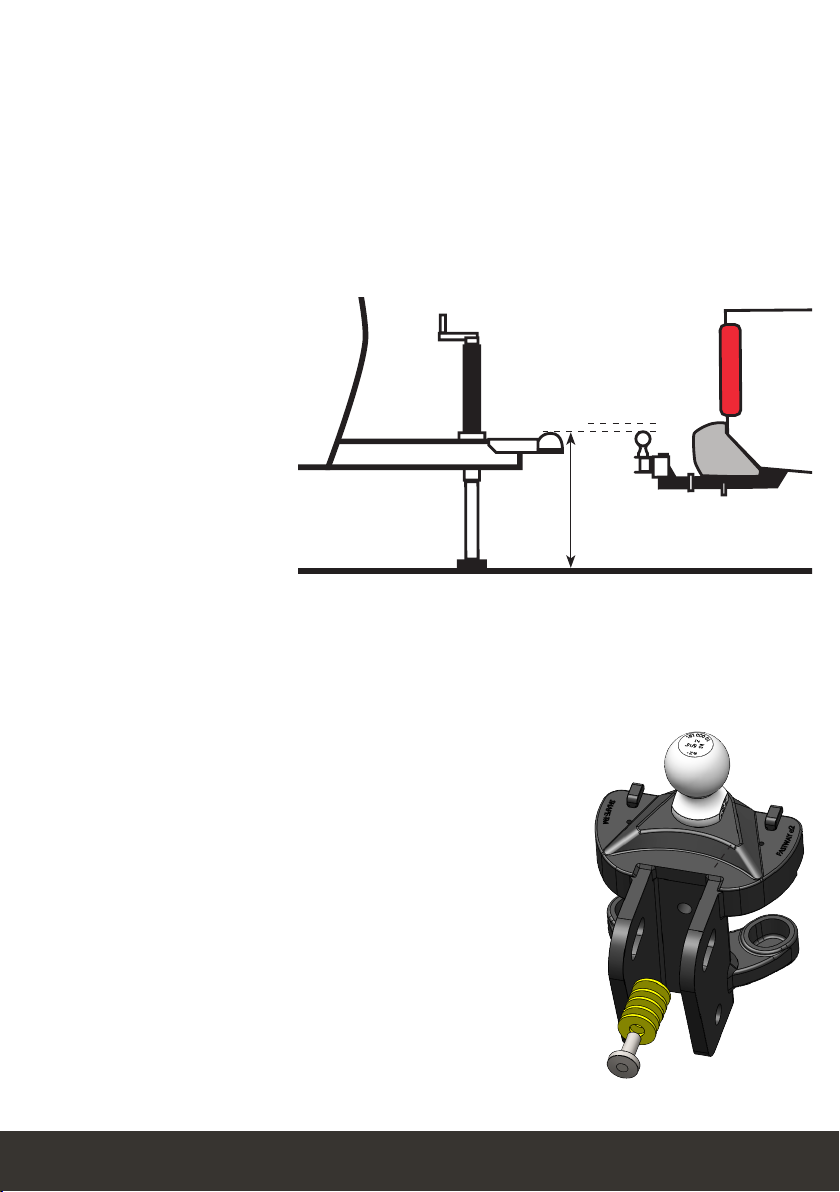
With the trailer parallel
to the ground, measure
to the top of the trailer
coupler. The top of the
hitch ball should be
initially placed between
0” and 1” above this
height. See Figure 1.
Attach Head to Shank
Insert the adjustable
shank into the receiver on
the tow vehicle and secure
it with the hitch pin and
clip.
Insert the spacer rivet
with the spacer washers
into the back of the hitch head to set the angle of the
hitch head. See Figure 2. Start with 6 spacer washers for
most setups. If your actual tongue weight is greater than
90% of the hitch’s max tongue weight rating (e.g. TW >
900 lb on a 1,000 lb hitch), you may want to start with 7
spacer washers, or more as the tongue weight approaches
the maximum hitch rating. Some setups with lighter
tongue weight may only need 5 spacer washers.
Slide the bolt channel around the shank and hold the
hitch head so that the top of the hitch ball is located
between 0” and 1” above the coupler height.
Hitch balls require a 1-7/8” socket and a torque wrench capable of approximately
420ft-lb torque for installation. Your nearest Fastway e2 hitch dealership will have
the tools needed and will usually install the hitch ball for a reasonable fee.
Figure 1 - Set top of hitch ball height between 0”
and 1” above the top of the coupler height, with the
trailer parallel to the ground.
Figure 2

10 fastwaytrailer.com
Insert a 3/4” shank bolt with a conical toothed
washer through the bottom hole in the bolt
channel and corresponding shank hole to hold
the head at the correct height. The teeth of the
washers should be against the bolt channel.
Slide another conical toothed washer, then nut
onto the other side of the bolt, and hand-tighten
them. Then repeat this process for the top shank
bolt. See Figure 4.
Figure 5
Figure 4
Figure 3
In some cases, the shank may need to be turned
upward, or a specialty length shank may be
needed so the ball can be placed at the correct
height. See Figure 3.
Use a wrench to tighten the angle set bolt until
it comes into contact with the shank and lifts the
head to where the spacer rivet also comes into
solid contact with the shank. Tighten the angle
set bolt an additional 1/2 turn. The hitch head
should be angled down slightly. See Figure 5.
The shank bolts will be fully tightened at the
end of the set up and adjustment process.
Extended bumper guards, truck campers, or
rear mounted spare tires can limit your turning
radius, and may lead to a collision between the
tow vehicle and trailer in a tight turn unless a
longer shank is used. If you are not able to turn
tightly with the standard length shank, consult
with your dealer about purchasing a longer
specialty shank.
11
A Product of Progress Mfg. Inc.
Step 4 - Sway Control Bracket Assembly
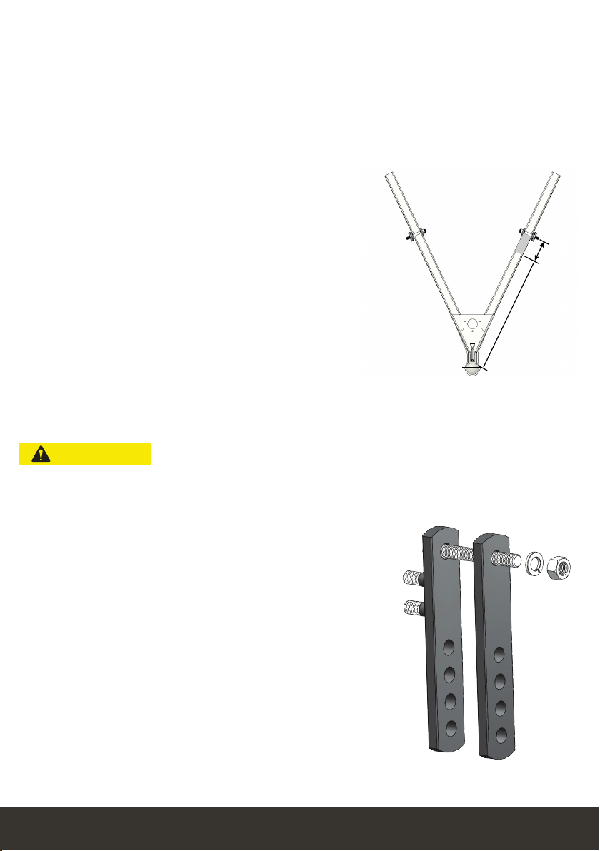
Sway Bracket Location
Measure from the center of the coupler along the trailer frame, and place a mark at
30” on both sides. This is the center mark for the sway control bracket assembly.
Make sure there are no gas lines, brake lines, or electrical wires located along the
frame that could be affected by the installation of the link plates. If so, re-route
or avoid the lines so their function will not
be disrupted or damaged by the link plate
installation.
Placing the sway control brackets centered at
30” back puts the least amount of stress on the
trailer and hitch components, and provides the
most comfortable ride. Sway brackets should be
placed at 30” whenever possible.
In some cases where there is an obstruction at
30” that cannot be avoided, like a battery rail
or propane tank support, the brackets may be
moved forward up to a minimum distance of
27” from the center of the coupler. See Figure 6.
27” min / 30” max
Figure 6
Assemble Link Plates
Insert one 1/2” x 4” bolt through the single hole
of the outside link plate so it goes through in the
opposite direction of the L-bracket mounting studs.
Insert the same bolt through the single hole on the
inside link plate. Slide on a split washer, and then
thread on a 1/2” nut a few turns. See Figure 7.
ATTENTION
ATTENTION
ATENCIÓN
ATENCIÓN
CAUTION
CAUTION
Do not use an impact wrench to tighten the link plate or L-bracket bolts.
Figure 7
12 fastwaytrailer.com
Insert the second bolt tight against the frame through the link plates from the
outside in. Slide on a split washer, then thread a 1/2” nut onto the bolt.
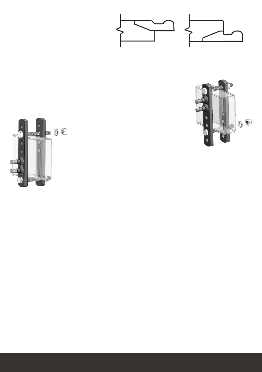
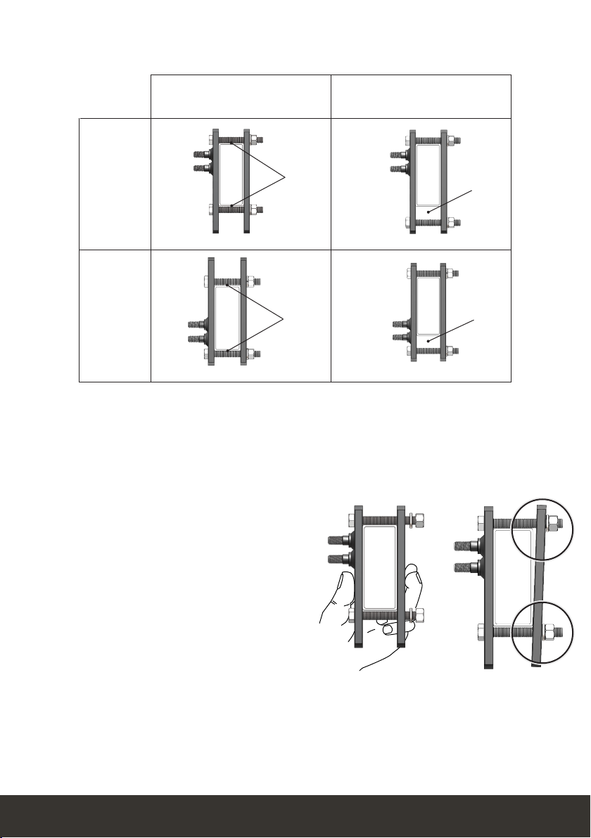
Bottom-mount Couplers
If your trailer has a bottom-mounted
coupler, is a V-nose trailer, or has
some other obstacle that makes installing the link plates in
the upright position difficult, install the link plates upside
down so that the single hole is below the trailer frame, and
the L-bracket studs are toward the bottom of the frame. See
Figure 10.
Top-mount Couplers
Place the link plates so the single hole is above the trailer
frame, and the L-bracket studs are toward the top of the
frame on the outside. See Figure 9.
Identify your coupler style.
See Figure 8.
Figure 10
Figure 9
Top-mount Bottom-mount
Figure 8
13
A Product of Progress Mfg. Inc.
Pinch the link plates tight to the trailer frame so both lay flat against the frame, and
hand-tighten the nuts on the inside. See Figure 12.
Tightening only one nut without first
pinching the link plates to the frame may
cause the inside link plate to bend when
torqued completely. It may also give you
a torque wrench reading that indicates
the link plates are tight, even though they
are not. See Figure 13.
Use wrenches to finish tightening the
link plate bolts until they are snug,
alternating from top to bottom bolt,
1/2 turn at a time. The link plate bolts
should be torqued to 65ft-lb. Figure 12
Correct
Figure 13
Incorrect
Figure 11
Bottom-mount
coupler or
V-nose trailer
Top-mount
coupler
Incorrect - Gap Between
Frame and Bolt
Correct - No Gaps
There should not be a gap between the trailer frame and the link plate bolts above
or below the frame. See Figure 11. Move electrical or propane lines if necessary.

14 fastwaytrailer.com
L-bracket Installation
For the first setup, slide the L-brackets onto the link plate studs with the studs in
the two center holes, with the friction plate facing away from the trailer. They may
need to be adjusted up or down later to get good weight distribution. Thread on the
nylock nuts and tighten them. See Figures 14 and 15.
When the weight distribution setup is complete, L-bracket nuts should be torqued to
75ft-lb.
Step 5 - Spring Bar Installation
Apply a thin layer of bearing grease to the top and bottom knuckles of the trunnion
spring bars. The bars will fit either side of the hitch; they are not side-specific. See
Step 10 - Regular Maintenance. Holding the bar perpendicular to the vehicle, place
the bottom knuckle into the bottom socket of the hitch head, then roll the bar until
the top knuckle passes the locking tab and is inserted into the top socket. See Figures
16 and 17. Repeat for the 2nd bar.
Figure 14 - Initial position for top-
mounted coupler.
Figure 15 - Setup for bottom-
mounted coupler.
Figure 17Figure 16
Grease
here
15
A Product of Progress Mfg. Inc.
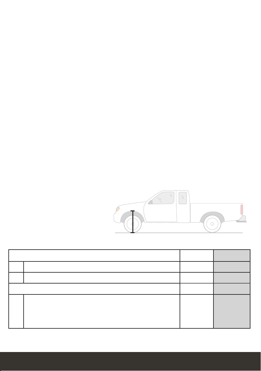
Measure from the ground
to fender through the
center-line of the axle.
RearFront
Figure 18
Weight Distribution Setup Table FRONT Example
ATow vehicle loaded for trip but still uncoupled from trailer 28”
BTrailer coupled but NO weight distribution 30”
Calculate height halfway between A and B (A+B)÷2=
29”
C
Trailer coupled with weight distribution engaged. Should
be at least halfway back to line A. Higher than this
may still be under adjusted. Lower than line A is over
adjusted. See Step 7 - Weight Distribution Adjustments.
28”-29”
Good
__________
29”-30”
Need More
Release the bars by lifting the locking tab and rolling the bar out of the top socket of
the hitch head.
Frequently apply a thin coat of bearing grease to the area of the spring bar knuckles
where they rub inside the hitch head sockets to reduce wear and make insertion
easier. This will also reduce hitch noise.
It is not necessary to apply lubricant to the joint where the spring bars rest on the
L-bracket. This may decrease the amount of sway control provided by the hitch.
Step 6 - Weight Distribution Setup
Before starting the weight distribution setup, turn off or disable the auto-level
system. See Appendix C, p. 28.
Good weight distribution is a critical component of the e2 hitch setup to get the best
performance from your hitch. Every tow vehicle and trailer combination will react
differently to weight distribution.
To correctly set up weight distribution you must take three measurements at the
front of your tow vehicle. See Figure 18. First, measure without the trailer coupled.
Next, measure with the trailer coupled, but with no weight distribution. Third,
measure with the trailer coupled and the spring bars in place.

16 fastwaytrailer.com
If you reach the top of the jack before the spring bars will swing into position, you
can use the Snap-up lever to lift the spring bars up and onto the L-brackets. Use the
L-pins to secure the spring bars on the L-brackets. See Figures 20 and 21.
With the spring bars resting on the L-bracket and the trailer and tow vehicle in line
with each other, check
to make sure there is a
minimum of 3” from
the end of the spring
bars to the center of the
L-brackets. See Figure 22.
If necessary, unload the
spring bars, then move
and tighten the sway
control bracket assembly.
Start by measuring the distance from the ground to the wheel well directly above the
front axle with the trailer uncoupled. Measure both driver and passenger sides,
and use the average of these two. Record this on line A of the weight distribution
setup table. A temporary piece of masking tape placed on the fender gives a clean
edge to measure to.
Back the tow vehicle to the trailer and lower the coupler onto the ball. Lock the
coupler and retract the tongue jack until it raises off the ground about 1”, so the full
tongue weight of the trailer is resting on the hitch ball.
Measure the tow vehicle height again exactly above the front axle, to the same point
that you measured to earlier when uncoupled. Record this on line B of the weight
distribution setup table on p. 15.
With the tow vehicle still coupled to the trailer, use the tongue jack to lift both
vehicles until you can swing the spring bars into place over the L-brackets. See
Figure 19. Then, retract the jack.
Figure 20 Figure 21
Figure 19

17
A Product of Progress Mfg. Inc.
Step 7 - Weight Distribution Adjustment
Weight distribution is only one of many things that influences sway. The
operator is responsible for making necessary adjustments to all contributing
factors in order to minimize sway.
Good adjustment:
You have most likely achieved good weight distribution adjustment if your
measurement on line C of the weight distribution setup table shows that front wheel
well measurement is at least halfway back to the original uncoupled measurement.
See line C on Weight Distribution Setup Table (p. 15) and Figure 23 below.
With the trailer coupled and weight distribution
engaged (spring bars in place and jack retracted),
measure the front wheel well height exactly as done
before for lines A and B. Record this new measurement
on line C of the weight distribution setup table on p. 15.
good
adjustment
needs more
weight distribution
See Weight Distribution
Setup Table on p. 15.
Figure 23
A uncoupled
C halfway back with WD
B coupled - no WD
AVERTISSEMENT
AVERTISSEMENT
ADVERTENCIA
ADVERTENCIA
WARNING
WARNING
Figure 22
3”
18 fastwaytrailer.com
AVERTISSEMENT
AVERTISSEMENT
ADVERTENCIA
ADVERTENCIA
WARNING
WARNING
If the measurement on line C is still higher than the calculated halfway point, you
need more weight distribution adjustment (see line C on Weight Distribution Setup
Table, Figure 18). With an under-adjusted setup your hitch is not unloading the rear
axle sufficiently, giving back as much steering control as it could, nor is it providing
as much friction as it could to help reduce trailer sway.
To correct under adjustment you must add more weight distribution force to the
hitch by adding spacer washers, or raising the L-brackets.
If this is the initial set up, use the tongue jack to unload the spring bars. Remove
the spring bars from the hitch head. Uncouple the trailer and pull the tow vehicle
forward. Remove the hitch head and add a spacer washer. Repeat step 6 and 7 to
readjust and check weight distribution.
Over or under adjusted weight distribution decreases tow vehicle stability.
Fixing Under or Over Adjustment:
If the hitch is transferring too little or too much weight, you must make adjustments
to the hitch setup. For changes during the initial setup we recommend adding or
removing spacer washers first to try and keep the spring bars parallel with the trailer
frame. This gives you more adjustment options later if needed, and may also reduce
some noise.
Once the maximum (9) or minimum (5) number of spacer washers has been
reached, further adjustments can be made by raising or lowering the L-brackets.
Minor adjustments later for changes in loading can usually be done by moving only
the L-brackets.
The distance from the tow vehicle rear axle to the hitch ball significantly affects
how the tow vehicle reacts to weight distribution adjustments. The same washer or
L-bracket change will have varying results on different vehicles.
Under adjustment occurs when there is not enough weight being transferred to the
front axles of the tow vehicle. See Figure 24.
Figure 24 - Under-adjustment
Good adjustment
(line C target)
Wheel well
measurement too high

19
A Product of Progress Mfg. Inc.
If you have reached the maximum number of spacer washers (9), or if adjusting
temporarily due to a change in vehicle loading, use the tongue jack to unload the
spring bars. Raise the L-brackets one hole. Move the spring bars back over the
L-brackets and retract the tongue jack. Measure the wheel wells and check for
proper weight distribution.
Repeat Steps 6 and 7 until the measurements show that the hitch is distributing
weight well.
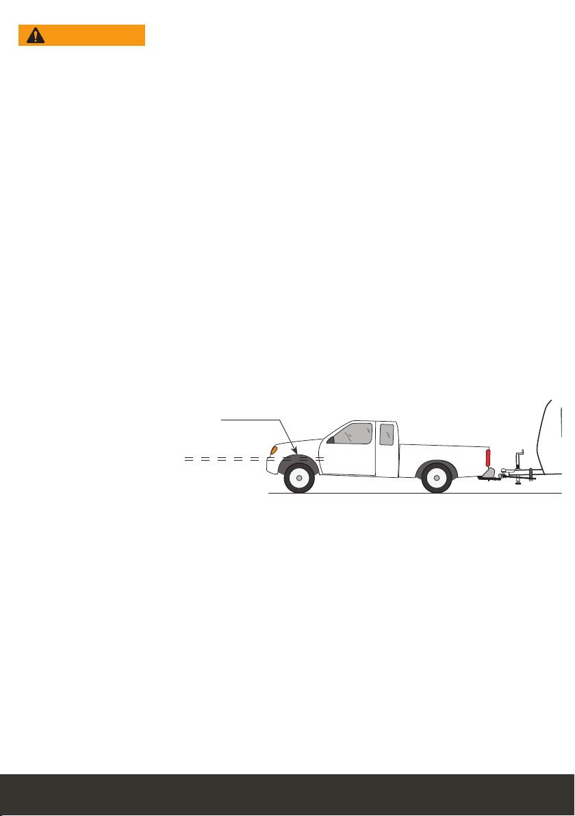
Over adjustment occurs when there is too much weight being transferred to the
front axle of the tow vehicle. See Figure 25.
Figure 25 - Over-adjustment
Wheel well measurement
too low
Good adjustment
(line C target)
If Cis lower than A, you need less weight distribution adjustment (see line C on
Weight Distribution Setup Table, Figure 18).
Overadjustment is a very dangerous situation where loss of control and jack-knifing
is possible, especially in wet or slick road conditions and/or with heavy trailers.
To correct over adjustment you must take some of the weight distribution force out
of the hitch by removing spacer washers, or lowering the L-brackets.
If this is the initial set up, use the tongue jack to unload the spring bars. Remove the
spring bars from the hitch head. Uncouple the trailer and pull the vehicle forward.
Remove the hitch head and remove a spacer washer. Repeat Steps 6 and 7 to adjust
and check weight distribution.
If you have reached the minimum number of spacer washers (5), or if adjusting
temporarily due to a change in vehicle loading, use the tongue jack to unload the
spring bars. Lower the L-brackets one hole. Move the spring bars back over the
L-brackets and retract the tongue jack. Measure the wheel wells and check for
proper weight distribution.
Repeat Steps 6 and 7 until the measurements show that the hitch is distributing
weight well.

20 fastwaytrailer.com
Step 9 - Final Tightening
Do not tow your trailer until all bolts and nuts have been checked and
properly tightened, and all pins and clips are securely in place.
Towing with loose bolts for an extended period of time can cause abnormal
stress on the hitch resulting in accident, severe injury, and property damage.
Step 8 - Trailer Pitch Adjustment
After achieving a good weight distribution setup you may need to adjust the pitch
(angle or attitude) of the trailer. Step back and look at the trailer to see if the front
appears to be tipped up or down excessively.
Measure the front and rear of the trailer again at the same points you did when
setting the trailer parallel to the ground in Step 3. Record these measurements on
the Trailer Pitch Adjustment chart. See Figure 26.
Find the difference between the front and rear heights.
AVERTISSEMENT
AVERTISSEMENT
ADVERTENCIA
ADVERTENCIA
WARNING
WARNING
Figure 26
Trailer Pitch Adjustment Chart Actual Example
Highest Measurement 20
Lowest Measurement -- 18
Difference between highest and lowest 2
If the difference between the highest and lowest measurement is 1-1/4” or more,
adjust the hitch ball height. If it is less than 1-1/4” different, complete Step9 and tow
a short distance with this setup to see how it handles before making any adjustments.
If the higher measurement is the front of the trailer, move the hitch head down one
hole position on the shank. If the lower measurement is the front of the trailer, move
the hitch head up one hole position on the shank.
Adjustments made to the ball height affect how weight is distributed. Moving it up
slightly reduces the amount of weight distribution you get from a particular setup.
Moving it down slightly increases the weight distribution from that same setup.
After making an adjustment to the ball height, return to Step 6 and 7 to check the
weight distribution measurements again. Adjust the weight distribution if necessary
until it falls within the guidelines. Check the trailer pitch again to see the difference
made by moving the hitch ball height. You may need to try several setups before you
get one that achieves good weight distribution and trailer pitch.
This manual suits for next models
4
Table of contents
Other Fastway Automobile Accessories manuals


