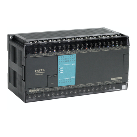
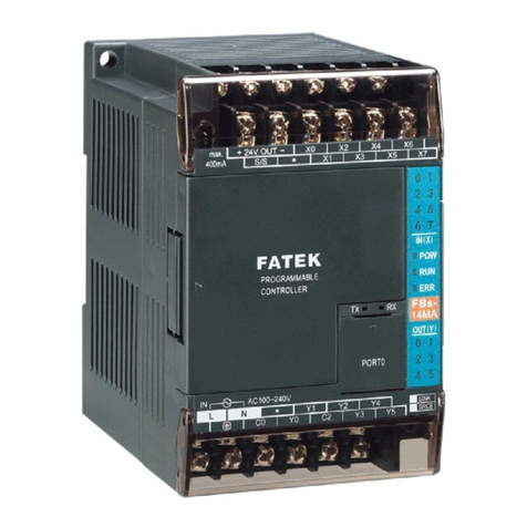
FATEK M Series User manual

INDEX
M Series PLC Expansion Module User Manual
INDEX
Chapter 1 List of Expansion Modules......................................................11
Chapter 2 Expansion of M-Series PLC ......................................................1
2-1 I/O Expansion Specifications .................................................................................................2
2-2 Digital I/O Expansion and I/O Channel Numbering.................................................................3
2-3 Analog I/O Expansion and I/O Channel Numbering ...............................................................5
2-4 Expansion Module Configuration Settings..............................................................................8
2-5 Expansion Module Firmware Update ...................................................................................10
Chapter 3 Installation and Wiring...............................................................1
3-1 Environmental Specifications .................................................................................................2
3-2 Installation Precautions..........................................................................................................3
Chapter 4 Power Wiring, Power Consumption Calculation, and Power
Sequence Requirements ................................................................................1
4-1 Specifications and Wiring of AC Power Module......................................................................2
4-2 Maximum Current Consumption of Expansion Module...........................................................5
4-3 Calculation Example of Power Capacity.................................................................................7
4-4 Requirement of Power Sequence in CPU Module & Expansion Module ................................8
Chapter 5 Digital Input Circuit....................................................................1
5-1 Digital Input Circuit Specifications ..........................................................................................2
5-2 24VDC Single-End Input Circuit and Wiring for SINK/SOURCE Input ....................................3
Chapter 6 Digital Output Circuit.................................................................1
6-1 Digital Output Circuit Specifications .......................................................................................2
6-2 Single-End Output Circuit.......................................................................................................3
6-3 Speed up the Single-End Transistor Output Circuit ................................................................6
6-4 Output Device Protection and Noise Suppression in DO Circuit.............................................7
Chapter 7 Left Side Expansion Module Specifications ............................1
7-1 Power Module Specifications .................................................................................................2
Chapter 8 Right Side High Speed Expansion Module Specifications .....1
8-1 High Speed Communication Expansion Module Specifications..............................................2
Chapter 9 Right Side Expansion Module Specifications........................1
9-1 Digital Input Expansion Module Specifications .......................................................................2
9-2 Digital Output Expansion Module Specifications ....................................................................5
9-3 Digital Input /Output Combo Expansion Module Specifications ............................................10
9-4 Analog Input Expansion Module Specifications....................................................................15
9-5 Analog Output Expansion Module Specifications .................................................................21
9-6 Analog Input/Output Combo Expansion Module Specifications............................................27
9-7 Temperature Expansion Module Specifications....................................................................31
9-8 Temperature Combo Expansion Module Specifications........................................................35
9-9 Load Cell Expansion Module Specifications.........................................................................38
Chapter 10 Left Side Expansion Dimensions............................................1

INDEX
M Series PLC Expansion Module User Manual
10-1 Power Module Dimensions ....................................................................................................2
Chapter 11 Right Side High Speed Expansion Dimensions.....................1
11-1 High Speed Communication Expansion Module Dimensions .................................................2
Chapter 12 Right Side Expansion Dimensions .........................................1
12-1 Digital Input Expansion Module Dimensions ..........................................................................2
12-2 Digital Output Expansion Module Dimensions........................................................................3
12-3 Digital Input/Output Combo Expansion Module Dimensions ..................................................5
12-4 Analog Input Expansion Module Dimensions .........................................................................6
12-5 Analog Output Expansion Module Dimensions ......................................................................8
12-6 Analog Input/Output Combo Expansion Module Dimensions ...............................................10
12-7 Temperature Expansion Module Dimensions .......................................................................11
12-8 Temperature Combo Expansion Module Dimensions...........................................................13
12-9 Load Cell Expansion Module Dimensions ............................................................................14
12-10 End Module Cover Dimensions............................................................................................16
Chapter 13 Expansion Module Troubleshooting.......................................1
13-1 Digital Input Expansion Module Troubleshooting....................................................................2
13-2 Digital Output Expansion Module Troubleshooting .................................................................2
13-3 Digital Input/Output Combo Expansion Module Troubleshooting
13-4 Analog Input Expansion Module Troubleshooting ..................................................................2
13-5 Analog Output Expansion Module Troubleshooting................................................................2
13-6 Analog Input/Output Expansion Module Troubleshooting
13-7 Temperature Input Expansion Module Troubleshooting ..........................................................3
13-8 Temperature Combo Expansion Module Troubleshooting
13-9 Load Cell Expansion Module Troubleshooting
Chapter 14 Repairs and Maintenance..........................................................1
14-1 Precautions............................................................................................................................2
14-2 Daily Maintenance .................................................................................................................3
14-3 Regular Maintenance.............................................................................................................4

Chapter 1 List of Expansion Modules
1
M-Series PLC Expansion Module User Manual
Manual for the FATEK M-Series PLC Expansion Module
Preface
This Manual provides important information related to the use of the FATEK M-Series PLC CPU Module.
Before using the product, be sure to read this Manual carefully in order to get familiar with and understand
its content. Should you have any questions or comments, please contact the FATEK distributor for detailed
warranty services and responsibility limit.
Warranty Service
The warranty period provided by FATEK for its product shall last for one year (or other period as
otherwise agreed) starting from the date when the product is sold and it will be offered under the pre-
conditions that there are no defects in product use.
Please contact FATEK or the local distributor in the event failure occurs on any of the FATEK products for
reasons not caused by man-made factors during the aforesaid warranty period. However, the failure due
to any of the following reasons shall not be covered by the warranty services:
1. The malfunction is due to the user’s failure in following the conditions, environment, operations,
installation and correct wiring method specified in this Manual.
2. The malfunction is due to the user’s failure in following the operating method originally designed.
3. The malfunction is not due to the reasons of the product.
4. The malfunction is not caused by the modification and the maintenance executed by FATEK.
5. The malfunction is caused by other types of
force majeure
factors such as natural disasters or man-
made negligence.
In the meantime, the aforesaid warranty services shall be limited to the FATEK product only and the
losses resulting from the product failure will not be covered in the warranty scope.
Limit of responsibilities
Unless it has been confirmed that the product is properly used, stored, installed and serviced and that it
has not been contaminated, abused, misused or improperly modified or repaired as being analyzed by
FATEK; otherwise, FATEK shall not be liable for any product-related particular damage, consequential
damage or derivative damage or even revenue loss or commercial loss that resulted from whatever
means.

Chapter 1 List of Expansion Modules
2
M-Series PLC Expansion Module User Manual
Precautions on using the product
Compliance with the application-related conditions
The user shall evaluate the suitability of FATEK product and shall install the product in the well-designed
equipment or system.
The user needs to check if the system, machinery or device currently used is compatible with the FATEK
product. If the user fails to confirm the compatibility or the suitability, then FATEK shall not be liable for
the suitability of the product.
When required by the customer, FATEK shall provide correlated third party certification to define the
value rating and the application restrictions that will be applicable for the product. However, the
aforesaid certification message shall not be considered as sufficient to determine the suitability of the
FATEK product, the final product, the machine, the system and other applications or relevant
combinations. Described below are certain applications that should be cautiously treated by the user. In
spite of this, the content described below shall neither be considered as having included all of the
intended product purposes nor suggesting that all of the following purposes shall be entirely suitable
for the product. For example, outdoors use, use in an area subjected to potential chemical
contamination or electrical interference or used under conditions or functions not mentioned in this
Manual or used with the system, machine and equipment that may create risks to life or properties.
Before working with the product, the user will be required to check if the entire system is marked with a
hazard sign and shall select the design that can ensure the safety such as the backup design, etc.
Otherwise, the user shall not be allowed to use the product in the application that will present personnel
and the property safety concerns. In no event shall FATEK be liable for the specifications, statutory
regulations or restrictions that will be used by the customer in the product combination or the product
operations.
When using the CPU Module, FATEK shall not be liable for the programs edited by the user or the
resulting consequences.

Chapter 1 List of Expansion Modules
3
M-Series PLC Expansion Module User Manual
Disclaimers
Dimensions and weight
The dimensions and the weight specified in the manual are nominal values only. Even if provided with
the tolerance, they cannot be used in the manufacturing purposes.
Performance data
The data specified in this Manual mean that the performance data obtained under FATEK’s test
conditions are provided for the user to confirm its compliance only. Therefore, the user is also required
to consider the actual application conditions. Therefore, actual performance shall be defined according
to the content of the guarantee and the limit of responsibilities established by FATEK.
Errors and negligence
The content of this Manual is provided through careful checking process and is considered as correct.
However, FATEK shall not be liable for the errors or the negligence that may be found in the text, printing
content and proofreading.
Change of specifications
The product specifications and accessories may be subject to change along with the technical
improvement or other reasons. In the event that the published specifications or performance need to
be changed or where significant structural change is required, FATEK will change the model number of
the product accordingly. If certain specifications of the product have changed, then FATEK will not give
the notice under the following situation: when it is required to use a special model number or create
particular specifications in order to support the customer’s application according to the instructions
given by the customer. To confirm actual specifications of the product to be purchased, please contact
the local FATEK distributor.

Chapter 1 List of Expansion Modules
4
M-Series PLC Expansion Module User Manual
Precautions for safety
Signs and meaning of safety precautions
The following signs will be used in this Manual in order to provide precautions that will be required for
using the M-Series PLC safely. These precautions are extremely important for using the product safely.
Please read the safety precautions carefully in order to get familiar with and understand the content and
the meaning of the aforesaid instructions.
Warning
Means a potentially dangerous situation that will result in death or serious
injury if not avoided. In the meantime, it may also lead to serious property
losses.
Caution
Means a potentially dangerous situation that may result in minor or
medium level injury or property losses if not avoided.
Means operations that must not be executed.
Means operations that must be executed.
Means general precautions.
Means the precautions relating to hot surfaces.
Means the precautions related to the wiring, grounding and electrocution of the electrical
system.

Chapter 1 List of Expansion Modules
5
M-Series PLC Expansion Module User Manual
Warning
Do not attempt to dismantle any module or touch the internal side of the module when
it is under energized status or it may lead to electrocution injury.
Do not attempt to touch any terminal or terminal board when the module is under
energized status, or it may lead to electrocution injury.
To ensure the system safety in order to avoid abnormal actions that may be caused by
man-made external factors or false actions resulting from the faulty PLC, it is required to
install the following safety measures in the external circuit (not within the PLC
procedure); otherwise, it may lead to serious accident.
The externally controlled circuit must be provided with emergency stop switch,
interlocking circuit, limit switch and similar safety measures. The PLC will stop outputting
the signals when encountering major failure alarm during the operations. However, the
errors in the I/O controller and the I/O register as well as other undetectable errors will
still trigger unexpected actions. To deal with the aforesaid errors, you are required to
install external safety measures to protect the system safety. If the output relay is
jammed, burnt or if the output transistor is damaged, then the PLC may still maintain its
output at the ON or OFF status.
To solve the aforesaid issues, it is required to install external safety measures to protect
the system safety. By installing the corresponding safety measures in the system and the
equipment, it allows you to maintain the safety of the entire system in spite of the fact
that communication errors or false actions have occurred during the operating process.
The user must take corresponding failure preventive measures in order to ensure safety
when the signal line is damaged or when the power is instantly disconnected or when
the signal is wrong, missing or abnormal as may be caused by other reasons. If failing to
taking the appropriate measures, it may lead to improper operations that may result in
serious accidents.

Chapter 1 List of Expansion Modules
6
M-Series PLC Expansion Module User Manual
Precautions
Do not touch the power module when the PLC is under energized status or when the
power source is disconnected. At this time, the power module might still present
extremely high temperature that can cause a scorching injury.
When connecting with the terminal board of the power module, the cable should be
secured with the appropriately sized Ferrule. If the cable is loose, it may lead to
burning or the failure of the power module.
The online editing shall be allowed only after confirming that the extended PLC cycle
duration will not result in any adverse impact or the system may not be able to read
the input signal.
After confirming that the I/O terminal is safe, you may transmit the required
parameters to other terminals such as PLC setting, I/O table and I/O register data,
etc. Otherwise, it may lead to unexpected actions if transmitting or modifying the
aforesaid data before that.

Chapter 1 List of Expansion Modules
7
M-Series PLC Expansion Module User Manual
Precautions for use
When using the M-Series PLC, please observe the precautions provided below.
Using the power
⚫Please use the voltage specified in the Manual. Incorrect voltage will lead to false action or burning
damage to the equipment.
⚫If the number of the module being connected exceeds the current rating of the power module, you
may not be able to start the CPU module or other modules.
⚫Please use the designated power source and then supply the power according to the specified voltage
and frequency rating. Special attention should also be given to the location subjected to unsteady
power supply, as incorrect power supply may result in false action.
⚫Before starting any of the following operations, be sure to disconnect the PLC power; or it may lead
to false action or electrocution injury.
(1) When installing or dismantling power module, I/O module, CPU module or any other type of
module.
(2) When connecting cables or executing the system wiring.
(3) When connecting or disconnecting the connector.
⚫When using the power module, be sure to observe following precautions.
(1) The voltage applied at the equipment output point or the connected load shall not be higher than
the rated specifications established for the power module.
(2) If it is required to put aside the power module for over 3 months, it shall be stored in a cool and
dry location in order to maintain its function at normal status.
(3) If the power module is improperly installed, it will result in the accumulation of heat as to cause the
aging or the damage of the component within. Therefore, it shall be properly connected and you are
also required to use the standard installation method.
Installation
⚫Do not install the PLC at the location near a high frequency noise interfering source.
⚫Confirm that the terminal board, the connector, the memory card, the peripheral communication wires
and other buckle-mounted devices are latched in position. Improper latching will result in false action.
⚫After connecting to the adjacent module, the buckle at the top or the bottom must be securely locked
(
i.e.,
properly latched). If failing to lock the buckle tightly, the module may not be able to achieve the
intended function.

Chapter 1 List of Expansion Modules
8
M-Series PLC Expansion Module User Manual
Wiring
⚫Please follow the instructions provided in the Manual in order to execute the wiring operations
correctly.
⚫Before connecting the power, please check the setting status of all wires and switches. Incorrect
wiring may result in burning damage to the equipment.
⚫After checking the installation position, you may start installing the terminal board and the
connector.
⚫During the wiring process, the label should be tagged on the module. If you tear off the label,
foreign mattes may get into the module as to cause a false action.
⚫To ensure normal heat dissipating function, please tear off the label after completing the wiring
operations. If retaining the label, it may lead to false action.
⚫Please use an EU-standard terminal to execute the wiring operations. Do not connect the terminal
with bare stranded wires. The aging or the breaking of wires may result in burning damage to the
equipment.
⚫The voltage applied to the input module shall not be higher than the input voltage rating or it may
result in burning damage to the equipment.
⚫The voltage or the load applied to the output module shall not be higher than the maximum
switch capacity. The over-voltage or the overload may result in burning damage of the equipment.
⚫Do not drag or bend the cable excessively. Such action may cause the breaking of the cable.
⚫Do not place any objects on the cable or other type of wires or it may cause the breaking of the
cable.
⚫Please set the grounding wire correctly for the power module and communication port to avoid
communication error and equipment malfunction caused by noise interference.
⚫It is recommended to use M series dedicated AC power modules to supply power to MPLC related
modules.
⚫It is recommended to use twisted-pair shielded cables for communication cables and ground them
properly.
Operating
⚫Before supplying power to the MPLC to start the operations, ensure that the setting of the data
register is correct without any mistakes.
⚫Before executing any of the following tasks, confirm that it will not bring about any adverse
impact on the system; otherwise, it may result in unexpected action.
(1) When changing the operating mode of the PLC (RUN Mode/STOP Mode).
(2) When executing compulsory enable/ compulsory disable for any of the data retained in the
register.
(3) When changing the present value of any bit or setting that has been logged in the register.
⚫Do not attempt to dismantle, repair or modify any module; or it may result in false action, fire or
electrocution.

Chapter 1 List of Expansion Modules
9
M-Series PLC Expansion Module User Manual
⚫It is required to protect the PLC from falling or from excessive vibration or impact.
⚫If the I/O is located at the “ON” position, when switching the “RUN Mode” to the “STOP Mode,”
the system will set the PLC output at the “OFF” position and then all output actions will be
disabled. Please ensure that the external load will not generate hazardous factors during the
aforesaid process.
⚫If the CPU module stops running due to catastrophic error, please set all of the output points on
the output module at the “OFF” position. The output status will be retained after being set as
the holding-type memory configuration parameters.
⚫If the status monitoring pages or the parameters are improperly set, it may result in unexpected
action. Even though the status monitoring pages or the parameters are correct, it is also
required to confirm that the controlled system will not be subject to adverse impact before
starting.
⚫When applying maximum level of voltage or when the power supplied to the operating switch is
interrupted suddenly during the Insulation Strength Test, it may result in the damage of the CPU
module. In this case, please use the variable resistor to increase or reduce the voltage level
gradually.
⚫Before conducting the Withstand Voltage Test or the Insulation Resistance Test, please separate
the wire grounding terminal of the power module from the functional grounding terminal.
Otherwise, it may result in burning damage to the equipment.

Chapter 1 List of Expansion Modules
10
M-Series PLC Expansion Module User Manual
Precautions for the application environment
⚫Please follow the instructions described in this Manual for carrying out the installation activities
correctly.
⚫Do not operate the control system in any of the following locations:
(1) The location exposed to direct sunlight.
(2) The location with temperature or humidity exceeding the specified range.
(3) The location vulnerable to dewing effect due to abrupt temperature changes.
(4) The location exposed to corrosive or combustible gases.
(5) The location exposed to dust (especially iron chips) or smoke.
(6) The location exposed to water, oil or chemicals.
(7) The location vulnerable to impact or vibration.
⚫When installing the system in any of the following locations, appropriate and effective
preventive measures should be taken:
(1) The location exposed to electrostatic or other type of noise.
(2) The location exposed to strong electromagnetic field.
(3) The location that may be exposed to radioactive pollution.
(4) The location near the power supply source.

Chapter 1 List of Expansion Modules
11
M-Series PLC Expansion Module User Manual
1
List of Expansion Modules

Chapter 1 List of Expansion Modules
12
M-Series PLC Expansion Module User Manual
List of Expansion Modules
Module Name
Specifications
Left Side Expansion Modules
Power Modules
MPA024-24
Input: 100~240VAC(50/60Hz),output: 24VDC 1A(Shared CPU dedicated power
supply and external Sensor power supply),Max. Power Consumption 24W.
MPA048-24
Input: 100~240VAC(50/60Hz),output: 24VDC 2A(Shared CPU dedicated power
supply and external Sensor power supply),Max. Power Consumption 48W.
Right Side Expansion Modules
High Speed
Communication
Modules
MHCM25
1 port RS232+1 port RS485 communication module.
MHCM55
2 ports RS485 communication module.
DI Modules
M16X
16 points 24VDC digital input
DO Modules
M16Y◇
16 points relay or transistor output
DIO Combo
Modules
M1616XY◇
16 points high-density 24VDC digital input,16 point high-density transistor
output,hybrid 40 pin I/O extension cable.
AI Modules
M04AD
4 channels, 14-bit analog input module (-10V~0V~+10V or -20mA~0mA~+20mA…)
M04ADR
4 channels,18-bit analog input module (-10V~0V~+10V or -20mA~0mA~+20mA…)
AO Modules
M04DA
4 channels,14-bit analog output module (-10V~0V~+10 or 0mA~+20mA…)
M04DAR
4 channels,16-bit analog output module (-10V~0V~+10 or 0mA~+20mA…)
AIO Combo
Modules
M0202AH
4 channels, 14-bit analog input module (-10V~0V~+10V or -20mA~0mA~+20mA…)
4 channels,14-bit analog output module (-10V~0V~+10 or 0mA~+20mA…)
Temperature
measurement
Modules
M04TC
4 channels, TC temperature input module with (K, J, T, E, R, B, N, S, mV),0.1℃
resolution.
M04TCR
4 channels, TC temperature input module with (K, J, T, E, R, B, N, S, mV),0.1℃
resolution.
Temperature
Measurement
Combo
Modules
M0202TH
2 channels, TC temperature input module with (K, J, T, E, R, B, N, S, mV),0.1℃
resolution.
2 channels, RTD temperature input module with(Pt-100, Pt-1000, JPt-100, JPt-
1000),0.1℃resolution.
Load Cell
Module
M02LC
2 channel, load cell measurement module with 24-bit resolution,Conversion
precision ±0.5%(25° C±5° C)
M02LCR
2 channel, load cell measurement module with 24-bit resolution,Conversion
precision ±0.01%(25° C±5° C)
End module
MRE
End module,This must be connected to the rightmost side of the CPU module or
the entire string of modules.
Remote Expansion Modules
Communication
Connector
MC0MN
Remote I/O Coupler (Modbus/ TCP)

Chapter 1 List of Expansion Modules
13
M-Series PLC Expansion Module User Manual
Peripheral and Accessory
High Density
DIO Cable
MFW40I-50
High-density I/O extension cable,40 pin Socket, 28AWG I/O cable,length 50cm
External
terminal
module
MFT40T
40 pin External terminal module
European
terminal Block
MFT18C
18 Pin European terminal Block
MFT06C
6 Pin European terminal Block
MFT04C
4 Pin European terminal Block
1. ◇: R-Relay output (CPU module and combo high-density DIO does not have); T-Transistor SINK(NPN) output; J-Transistor
SOURCE(PNP) output.
2. Right side expansion modules are divided into standard type and high-speed type. High-speed type can only accept up to 6 units.
And it must be installed in the first 6 positions on the right side of the CPU module.

Chapter 2 Expansion of M-Series PLC
1
M-Series PLC Expansion Module User Manual
2
Expansion of M-Series PLC
2-1 I/O Expansion Specifications ..................................................................................................................2
2-2 Digital I/O Expansion and I/O Numbering........................................................................................3
2-3 Analog I/O Expansion and I/O Numbering.......................................................................................5
2-4 Expansion Module Configuration Settings.......................................................................................8
2-5 Expansion Module Firmware Update............................................................................................... 10

Chapter 2 Expansion of M-Series PLC
2
M-Series PLC Expansion Module User Manual
The expansion of M-series PLC means when the resources provided by the M-series CPU module are
insufficient or the interface not provided by the CPU module. The number of I/O or interface types can be
expanded by adding expansion modules. The expansion of M series PLC can be divided into two categories:
I/O expansion and communication port expansion.
2-1 I/O Expansion Specifications
The expansion of M Series PLC I/O consists of Digital I/O (DI/O, which status is represented by a single
bit) and the Numeric I/O (NI/O, which status is represented by a 16-bit Word). Either the DI/O or the NI/O
expansion is realized through expansion modules cascaded thru the usage of the “I/O Output Expansion
Connector” located at the right side of M Series PLC or expansion module.
The I/O points of M-Series PLC are limited to 2048 points of DI/O (1024 points each for DI and DO),512
words of NI/O (256 points each for NI and NO). Hardware limitations: ①. A maximum number of 64
modules can be used in the expansion. ②The number of expansion modules that can be connected in
series in each segment of the M-series PLC is limited to 16 units, and expansion modules or branch modules
must be used for extension between each segment.
Caution
1. If the I/O points of the application system exceed one of the limitations (1024 DI,1024 DO,256 NI,
256 NO), while startup the M-Series PLC will treat this as an illegal I/O configuration, which in return
will flag as an error situation by turn on the “ERR” LED. The corresponding error code will also be
indicated in the CPU status register (DR35361).
2. The maximum number of expansion modules of M-Series PLC is 64. Beyond this numbers will be
treated as an invalid I/O configuration and the CPU Module will stop its operation, which in return
will flag as an error situation by turn on the “ERR” LED. The corresponding error code will also be
indicated in the CPU status register (DR35361).
3. The number of expansion modules that can be connected in series in each segment of the M-series
PLC is limited to 16 units, and expansion modules or branch modules must be used for extension
between each segment.
Warning
1. The maximum length of the I/O expansion cable for M-Series PLC is @5 meters. Cables longer than
that will cause incorrect I/O operation because of excess signal delay in hardware or noise pickup,
resulting in damage to equipment or posing hazard to operating personnel. Since this kind of
situation cannot be detected by the CPU Module, users are advised to take extra cautions and
necessary measures.

Chapter 2 Expansion of M-Series PLC
3
M-Series PLC Expansion Module User Manual
2-2 Digital I/O Expansion and I/O Numbering
Digital I/O means I/O with the discrete type status, including digital input (with initial X in DI
numbering) and digital output (with initial with Y in DO numbering). The DI and DO of M Series PLC can
both be expanded up to 1024 points (numbered as X0~X1023 and Y0~Y1023, each with 1024 points).
The status of input contacts (X0~X1023) of PLC come from the input signal connected to the digital
input terminal block on CPU Module or expansion module; while the status appears at digital output
terminal block of CPU Module and expansion module reflects the digital output relay (Y0~Y1023) status
inside PLC.
On M Series CPU Module, at the position right of the external terminal connector, there have labels
indicate the corresponding signal name. They label each terminal with numbers representing the
corresponding digital input contact Xn and digital output relay Yn. In the example of the CPU module in
ME3C6-1616T, The labels of the digital input contacts on the left side of the external terminal connector
are X0~15, S/S and the labels of the digital input contacts on the right side of the external terminal
connector are Y0~Y15, COM. Users only need to locate the printed label for each terminal to find out its
I/O number. The LED status display region also indicates the ON/OFF status for all DI(X0~X15) and
DO(Y0~Y15) on the main unit. Users can easily find each terminal with its I/O number and LED status
indication.
CPU Module Digital I/O Number

Chapter 2 Expansion of M-Series PLC
4
M-Series PLC Expansion Module User Manual
While the various expansion modules other than the CPU module have the same printed labels on the
input/output terminals as the CPU module do, these labels are only relative I/O numbers, different from
the absolute I/O numbers on CPU module. The number of a terminal only represents its order on the
expansion module. For example, the first contact is 1, the second is 2, etc. All numbers on the expansion
module begin with 1. The actual number of digital input contact or the output replay, however, is
determined by summing the numbers on all previous expansion modules and the CPU module. See the
following figure and its calculation.
Expansion Module Digital I/O Number
As shown in the above figure,10 output points on the 2nd expansion module M16X. Because the top X
numbers of the previous two units are 15 and 16, respectively, the number of input contact X41 on second
expansion unit should be:
X( 15+16+10 ) = X41
This manual suits for next models
10
Table of contents
Other FATEK Controllers manuals
Popular Controllers manuals by other brands

GameSir
GameSir G3s Enhanced Edition user manual
Azbil
Azbil SLPC1F user manual
SMC Networks
SMC Networks VCHR30 Series Installation and maintenance manual
We Care Solar
We Care Solar Suitcase installation guide
Streck
Streck CD-Chex CD34 Instructions for use
ATI Technologies
ATI Technologies TRACON FPT 130 Installation and operation manual

