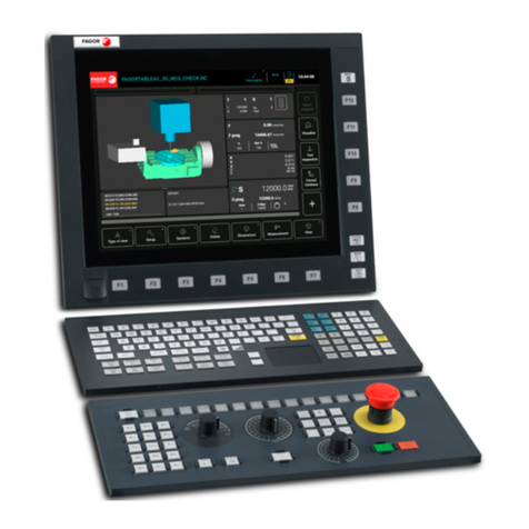
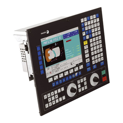
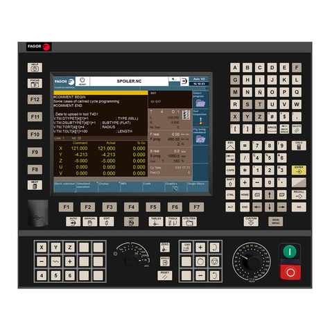
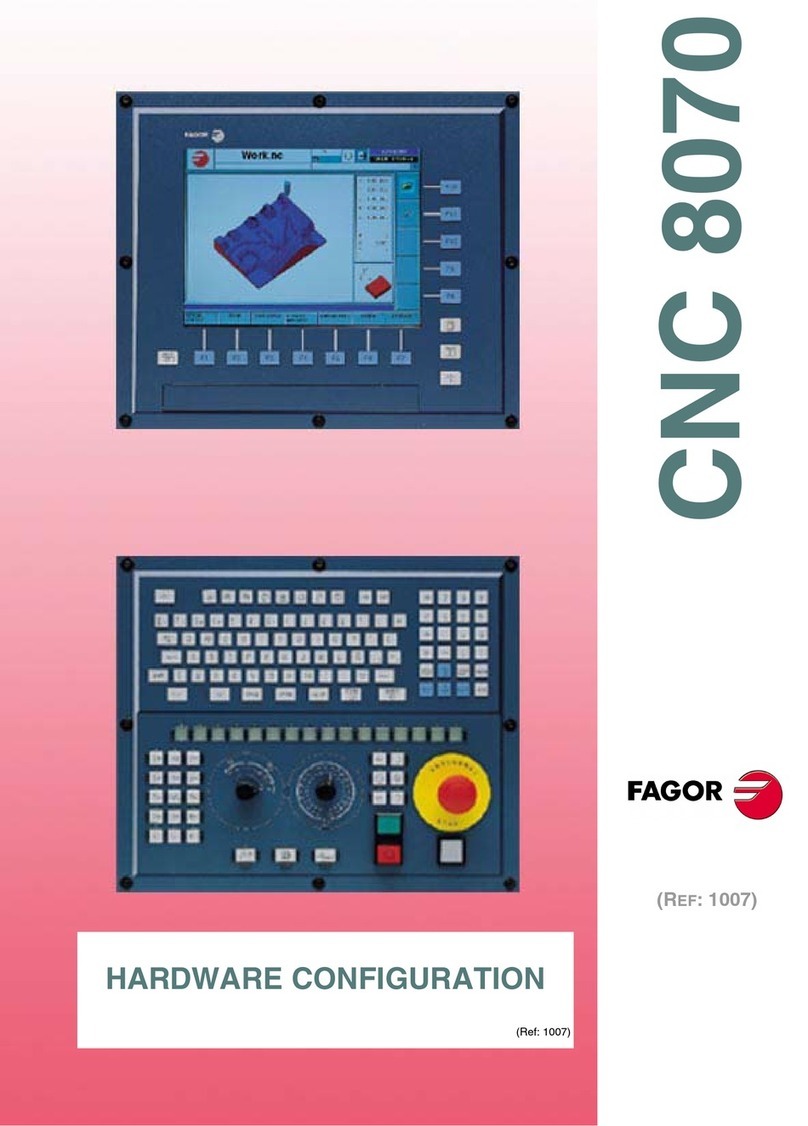
Fagor CNC 8070 Quick guide

CNC 8070
REF. 0501
HARDWARE CONFIGURATION
Ref. 0501


Hardware configuration
Unauthorized copying or distributing of this software is prohibited.
All rights reserved. No part of this documentation may be transmitted, transcribed, stored in a backup device
or translated into another language without Fagor Automation’s consent.
Microsoft
®
and Windows
®
are registered trademarks of Microsoft Corporation, U.S.A.


Hardware configuration
PRELIMINARY WARNINGS
MACHINE SAFETY
It is up to the machine manufacturer to make sure that the safety of the machine is enabled
in order to prevent personal injury and damage to the CNC or to the products connected to it.
On start-up and while validating CNC parameters, it checks the status of the following safety
elements:
• Feedback alarm for analog axes.
• Software limits for analog and sercos linear axes.
• Following error monitoring for analog and sercos axes (except the spindle) both at the
CNC and at the drives.
• Tendency test on analog axes.
If any of them is disabled, the CNC shows a warning message and it must be enabled to
guarantee a safe working environment.
FAGOR AUTOMATION shall not be held responsible for any personal injuries or physical
damage caused or suffered by the CNC resulting from any of the safety elements being
disabled.
HARDWARE EXPANSIONS
FAGOR AUTOMATION shall not be held responsible for any personal injuries or physical
damage caused or suffered by the CNC resulting from any hardware manipulation by
personnel unauthorized by Fagor Automation.
If the CNC hardware is modified by personnel unauthorized by Fagor Automation, it will no
longer be under warranty.
COMPUTER VIRUSES
FAGOR AUTOMATION guarantees thatthesoftware installed contains nocomputer viruses.
It is up to the user to keep the unit virus free in order to guarantee its proper operation.
Computer viruses at the CNC may cause it to malfunction. An antivirus software is highly
recommended if the CNC is connected directly to another PC, it is part of a computer network
or floppy disks or other computer media is used to transmit data.
FAGOR AUTOMATION shall not be held responsible for any personal injuries or physical
damage caused or suffered by the CNC due a computer virus in the system.
If a computer virus is found in the system, the unit will no longer be under warranty.


Hardware configuration
CNC 8070
REF. 0501
i
INDEX
1 CNC structure............................................................................................................... 2
1.1 Possible configurations ............................................................................................. 3
1.2 Additional hardware .................................................................................................. 8
2 Heat dissipation. Central unit (cpu) enclosure.............................................................. 9
3 PCI central unit. .......................................................................................................... 12
3.1 PCI. Dimensions ..................................................................................................... 13
3.2 PCI. Technical characteristics ................................................................................. 14
3.3 PCI. Characteristics of the enclosure...................................................................... 15
3.4 PCI. Elements (connectors) .................................................................................... 17
3.5 PCI. CAN and Sercos
®
communications board. ..................................................... 18
3.6 PCI. CPU board connectors.................................................................................... 19
3.7 PCI. Relay for the emergency chain ....................................................................... 20
4 PC104 central unit. General description..................................................................... 21
4.1 PC104. Dimensions of the central unit without monitor .......................................... 23
4.2 PC104. Technical characteristics ............................................................................ 24
4.3 PC104. Characteristics of the enclosure................................................................. 26
4.4 PC104. Elements (connectors) ............................................................................... 27
4.5 PC104. Power supply and battery........................................................................... 29
4.6 PC104. CAN and Sercos
®
communications board. ................................................ 31
4.7 PC104. CPU board connectors ............................................................................... 32
4.8 PC104. Connectors for a floppy disk drive or IDE................................................... 33
4.9 PC104. Relay for the emergency chain .................................................................. 34
5 PC-104 central unit with LCD-10 monitor ................................................................... 35
5.1 LCD-10. Dimensions ............................................................................................... 36
5.2 LCD-10. Characteristics of the enclosure ............................................................... 37
6 PC-104 central unit with LCD-10K monitor................................................................. 38
6.1 LCD-10K. Dimensions............................................................................................. 39
6.2 LCD-10K. Characteristics of the enclosure ............................................................. 40
6.3 LCD-10K. Elements (connectors) ........................................................................... 41
7 PC-104 central unit with LCD-12 monitor ................................................................... 43
7.1 LCD-12. Dimensions ............................................................................................... 44
7.2 LCD-12. Characteristics of the enclosure ............................................................... 45
7.3 LCD-12. Elements (connectors).............................................................................. 46
8 Set of keyboard and operator panel (OP-Panel-H/E) ................................................. 47
8.1 Dimensions ............................................................................................................. 48
8.2 Technical characteristics ......................................................................................... 49
8.3 Securing characteristics .......................................................................................... 50
8.4 Elements ................................................................................................................. 51
9 Keyboard (Key Board Panel H) .................................................................................. 52
9.1 Dimensions ............................................................................................................. 53
9.2 Technical characteristics ......................................................................................... 54
9.3 Securing characteristics .......................................................................................... 55
9.4 Elements ................................................................................................................. 56
10 Operator panel (Jog panel)......................................................................................... 57
10.1 Dimensions ............................................................................................................. 58
10.2 Technical characteristics ......................................................................................... 59
10.3 Securing characteristics .......................................................................................... 60
10.4 Elements ................................................................................................................. 61
11 “Handwheel + E-stop button” module......................................................................... 62
11.1 “Handwheel + E-stop button” module dimensions .................................................. 63
12 Mouse module ............................................................................................................ 64
12.1 Mouse dimensions .................................................................................................. 65
13 Floppy disk drive......................................................................................................... 66
13.1 Floppy disk drive dimensions.................................................................................. 67
13.2 Floppy disk drive installation ................................................................................... 68
Hardware configuration
CNC 8070
REF. 0501
ii
14 Emergency battery ..................................................................................................... 69
14.1 Battery dimensions.................................................................................................. 70
14.2 Elements (connectors) ............................................................................................ 71
15 Remote modules ........................................................................................................ 72
15.1 Consumption of the remote modules ...................................................................... 74
15.2 Power Supply .......................................................................................................... 75
15.3 Digital inputs and outputs........................................................................................ 76
15.4 Analog inputs and outputs....................................................................................... 79
15.5 Counters.................................................................................................................. 80
16 CAN connection.......................................................................................................... 81
16.1 Module identification and connection...................................................................... 82
17 Sercos
®
Connection ................................................................................................... 85
17.1 Module identification and connection...................................................................... 86
17.2 Data exchange via Sercos
®
.................................................................................... 87
18 Overall connection...................................................................................................... 88

Hardware configuration
8070 CNC
REF. 0501
1
The CNC is ready to be used in industrial environments especially on
milling machines, lathes, etc.
It allows controlling the machine movements and devices.
Technical information
Refer to this manual for technical information about the CNC
hardware.
Safety conditions
In order to avoid personal injuries and damage to this product or to
those connected to it, read carefully the section on safety conditions
in the introduction to this manual.
Start-up
Before starting the CNC up, read the indications of this chapter of the
manual.
Do not get into the inside of the unit. Only personnel authorized by
Fagor Automation may manipulate the inside of this module.
Install the CNC away from coolants, chemical products, etc. that could
damage it.
Place the power supply breaker easily accessible and at distance
between 0.7 m (2 ft) and 1.7 m (5 ft 7") from the floor.
The external 24 Vdc power supply must be stabilized.
Do not handle the connectors with the unit connected to AC power.
Before doing it, make sure that the unit is disconnected.
Check that the machine where this CNC is installed meets the directive
89/392/CEE.

Hardware configuration
8070 CNC
CNC structure
REF. 0501
2
1 CNC structure
CPU (Central Unit) / Monitor
The central unit is located on the rear of the monitor. There are 10”
and 12” LCD monitors depending on the type of central unit.
The PC104 central unit is available without monitor, thus being
possible to install it remotely. A standard off-the-shelf VGA monitor
may be used. In this case, the maximum cable length is 10 meters.
Keyboard and operator panel
The keyboard and the operator panel may go separately or integrated
into a single keyboard-operator-panel.
The keyboard and the operator panel may also be integrated into the
monitor.
Peripherals
Such as floppy disk drives, CD-ROM drive or mouse. They may be
connected to the CNC through specific cables.
PCI PC104
Dimensions (without monitor) (294 x 206 x 117.5) mm
(11.57 x 8.11 x 4.62) inch
(376.5 x 280 x 121.75) mm
(14.82 x 11.02 x 4.79) inch
Monitor size 12” LCD 10” LCD
12” LCD
Without monitor
HD Yes Yes
Compact flash No Option
Battery for emergency turn-off No Option
Ethernet T base 10/100Mhz T base 10/100Mhz
Modem / Fax 56K 56K
USB ports No 2
Battery of the CMOS CR2032 CR2450
(access from the outside)

Hardware configuration
8070 CNC
CNC structure
REF. 0501
3
1.1 Possible configurations
Basic hardware
The hardware elements described in this manual are identified as
follows.
Additional hardware
•“E-stop + handwheel” unit.
•Mouse unit.
•Floppy disk drive.
Emergency battery
Optional when having a PC104 central unit.
It ensures proper operation of the CNC when there is a mains outage.
In those cases, the CNC stops the machine and the CNC turns off in
a controlled manner.
PCI PCI central unit.
PC104 PC104 central unit.
LCD-10 10” LCD monitor.
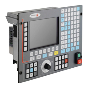
LCD-10K 10” LCD monitor with integrated keyboard and operator panel.
LCD-12 12” LCD monitor.
OP-Panel-H/E Keyboard with integrated operator panel. Available either with an
electronic handwheel (OP-Panel-H) or with an emergency stop button
(OP-Panel-E).
Key Board Panel H Keyboard.
Jog Panel Operator panel.

Hardware configuration
8070 CNC
CNC structure
REF. 0501
4
(UC-PCI) + (LCD-12) + (OP-Panel-H/E)
The central unit offers access from the front panel to the floppy disk
drive and to the connectors for the keyboard and the mouse through
a PS-2 connector.
The keyboard and the operator panel are a single module. The
operator panel may have either an emergency button (E-stop) or a
handwheel.
For further information about the central unit and the monitor, refer to
section "3 PCI central unit." For further information about the
keyboard, refer to section "8 Set of keyboard and operator panel
(OP-Panel-H/E)".
Basic connection
•The CAN bus is used to connect the various elements that make
up the CNC.
•The Sercos
®
bus is used to communicate with FAGOR drives. It is
also possible to communicate with analog drives using the CAN
bus.
Remember that the ground terminals of all the elements making up
the system must be connected to a single ground point.
(UC-PCI) + (LCD-12) OP-Panel-H/E

Hardware configuration
8070 CNC
CNC structure
REF. 0501
5
(UC-PC104) + (LCD-12) + (OP-Panel-H/E)
The keyboard and the operator panel are a single module. The
operator panel may have either an emergency button (E-stop) or a
handwheel.
For further information about the central unit and the monitor, refer to
section "7 PC-104 central unit with LCD-12 monitor" For further
information about the keyboard and the operator panel, refer to
section "8 Set of keyboard and operator panel (OP-Panel-H/E)".
Basic connection
•The CAN bus is used to connect the various elements that make
up the CNC.
•The Sercos
®
bus is used to communicate with FAGOR drives. It is
also possible to communicate with analog drives using the CAN
bus.
Remember that the ground terminals of all the elements making up
the system must be connected to a single ground point.
(UC-PC104) + (LCD-12) OP-Panel-H/E

Hardware configuration
8070 CNC
CNC structure
REF. 0501
6
(UC-PC104) + (LCD-10) + (Key Board Panel H) + (Jog Panel)
The keyboard and the operator panel are independent modules.
For further information about the central unit and the monitor, refer to
section "5 PC-104 central unit with LCD-10 monitor" For further
information about the keyboard, refer to section "9 Keyboard (Key
Board Panel H)". For further information about the operator panel,
refer to section "10 Operator panel (Jog panel)".
Basic connection
The keyboard is connected through the PS-2 port. The CAN bus
is used to connect the rest of the elements that configure the CNC.
The Sercos
®
bus is used to communicate with FAGOR drives. It is
also possible to communicate with analog drives using the CAN
bus.
Remember that the ground terminals of all the elements making up
the system must be connected to a single ground point.
(UC-PC104) + (LCD-10)
Key Board Panel H Jog Panel

Hardware configuration
8070 CNC
CNC structure
REF. 0501
7
(UC-PC104) + (LCD-10K)
The keyboard and the operator panel are integrated into the monitor.
For further information about the central unit and the monitor, refer to
section "6 PC-104 central unit with LCD-10K monitor"
Basic connection
The CAN bus is used to connect the various elements that make
up the CNC.
The Sercos
®
bus is used to communicate with FAGOR drives. It is
also possible to communicate with analog drives using the CAN
bus.
Remember that the ground terminals of all the elements making up
the system must be connected to a single ground point.
(UC-PC104) + (LCD-10K)

Hardware configuration
8070 CNC
Heat dissipation. Central unit (cpu) enclosure
REF. 0501
9
2 Heat dissipation. Central unit (cpu) enclosure
The working temperature of the central unit enclosure must not
exceed 45ºC (113ºF). To ensure that it does not exceed this
temperature, the enclosure must meet the following requirements:
•Have enough surface inside to evacuate the heat generated inside
and keep the ambient conditions within the working temperature
range.
•Respect the minimum distances recommended between the
enclosure walls and the central unit. See "3.3 PCI.
Characteristics of the enclosure". See "4.3 PC104.
Characteristics of the enclosure".
Calculation of the surface needed for heat dissipation
The expressions have been obtained for an enclosure having a 2 mm
wall and made out of aluminum. When using internal ventilation, the
fan must be located 30 mm off the bottom.
To calculate the total surface required for the enclosure, in order to
dissipate the heat generated in it, the following data must be
considered.
A(m
2
) Required total surface.
P (W) Total power dissipated by all the elements that generate
heat inside the enclosure, including the power supply
and the fan, if there is one.
Ta (ºC) Ambient temperature (outside the enclosure).
Ti (ºC) Temperature inside the enclosure.
∆t (ºC) Temperature difference (Ti-Ta).
Q(m
3
/h) Air flow supplied by the fan, if there is one.
Dissipating surface
Only surfaces dissipating heat by convection will be considered, the
top and the rear of the enclosure. The rest of the surfaces are not to
be considered when calculating the total surface.
Power dissipated by the CNC
The maximum power dissipated by the central unit PCI and PC104 are
100 watts.
Ti
Ta
A
P
30mm
Q

Hardware configuration
8070 CNC
Heat dissipation. Central unit (cpu) enclosure
REF. 0501
10
Heat dissipation by natural convection
Heat dissipation by forced convection with internal fan
Fan whose air flow Q = 13.6 m
3
/h facing down.
Fan whose air flow Q = 13.6 m
3
/h facing up.
Fan whose air flow Q = 30 m
3
/h facing down.
Unpainted surface.
Surface with smooth metallic enamel.
AP
5∆T⋅
--------------=
AP
5,7 ∆T⋅
------------------=
Ti
Ta A
P
Unpainted surface.
Surface with smooth metallic enamel.
AP
5,6 ∆T⋅
------------------=
AP
7,6 ∆T⋅
------------------=
Ti
Ta A
P
Unpainted surface.
AP
5,8 ∆T⋅
------------------=
Ti
Ta A
P
Unpainted surface.
Surface with smooth metallic enamel.
AP
6,75 ∆T⋅
--------------------=
AP
9,1 ∆T⋅
------------------=
Ti
Ta A
P

Hardware configuration
8070 CNC
Heat dissipation. Central unit (cpu) enclosure
REF. 0501
11
Fan whose air flow Q = 102 m
3
/h facing down.
Heat dissipation by air flow to the outside using a fan
Heat dissipation by forced convection with hot air flow to the outside
using a fan and ambient air intake through the holes located at the
bottom of the enclosure.
For this case, the volume of air flow is calculated necessary to
evacuate the heat generated inside the enclosure. The fan's air flow
is calculated according to the power dissipated by the CNC and the
fan itself as well as the inside and outside temperatures.
Bear in mind that this air flow through the unit extracts hot air to the
outside, but it allows dirt into the enclosure. Thus, a filter should be
installed to maintain the ambient conditions allowed.
Unpainted surface.
Surface with smooth metallic enamel.
AP
7,5 ∆T⋅
------------------=
AP
9,8 ∆T⋅
------------------=
Ti
Ta A
P
Unpainted surface.
V3,8 P⋅
∆T
---------------
=
40
40
Ø6

Hardware configuration
8070 CNC
PCI central unit.
REF. 0501
12
3 PCI central unit.
Monitor
12.1” LCD monitor (18-bit color). Resolution 800x600.
Description
It has the following elements:
•3.5” floppy disk drive.
•It may be accessed from the front panel for peripherals.
•CAN and Sercos
®
communications board.
•Board for connecting to Ethernet and peripherals (PC-compatible
keyboard, mouse with PS-2 connector and PC monitor).
•It is possible to connect a PC-compatible keyboard or mouse using
a PS-2 connector from the front panel.
Power supply
Universal AC power supply. Connect it through a separate shielded
110 VA transformer with an output voltage between 84Vac and 264
Vac.
Other manuals for CNC 8070
9
Table of contents
Other Fagor Control System manuals

Fagor
Fagor CNC 8070 Quick guide

Fagor
Fagor CNC 8065 Quick guide

Fagor
Fagor CNC8 070 Administrator guide

Fagor
Fagor CNC 8055 T User guide

Fagor
Fagor CNC 8070 User manual

Fagor
Fagor CNC 8060 User manual

Fagor
Fagor CNC 8035 User manual

Fagor
Fagor CNC 8060 User manual

Fagor
Fagor 8055 M Owner's manual

Fagor
Fagor 8065 User manual

Fagor
Fagor CNC 8055 TC User manual

Fagor
Fagor CNC 8070 Quick guide

Fagor
Fagor CNC 8060 LASER User manual

Fagor
Fagor 8070 BL Owner's manual

Fagor
Fagor CNC 8065elite T User manual

Fagor
Fagor CNC 8060 User manual

Fagor
Fagor 101 User manual

Fagor
Fagor CNC 8060 User manual

Fagor
Fagor CNC 8060 Quick guide

Fagor
Fagor CP-G905 Setup guide