GSK983Ta-H/ GSK983Ta-V Turning CNC System Connection Manual
Contents
Precautions...................................................................................................................................1
1.NC Unit Interfaces......................................................................................................................3
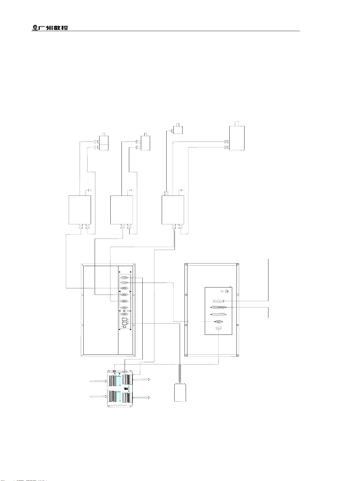
2.Interconnect Block Diagram........................................................................................................4
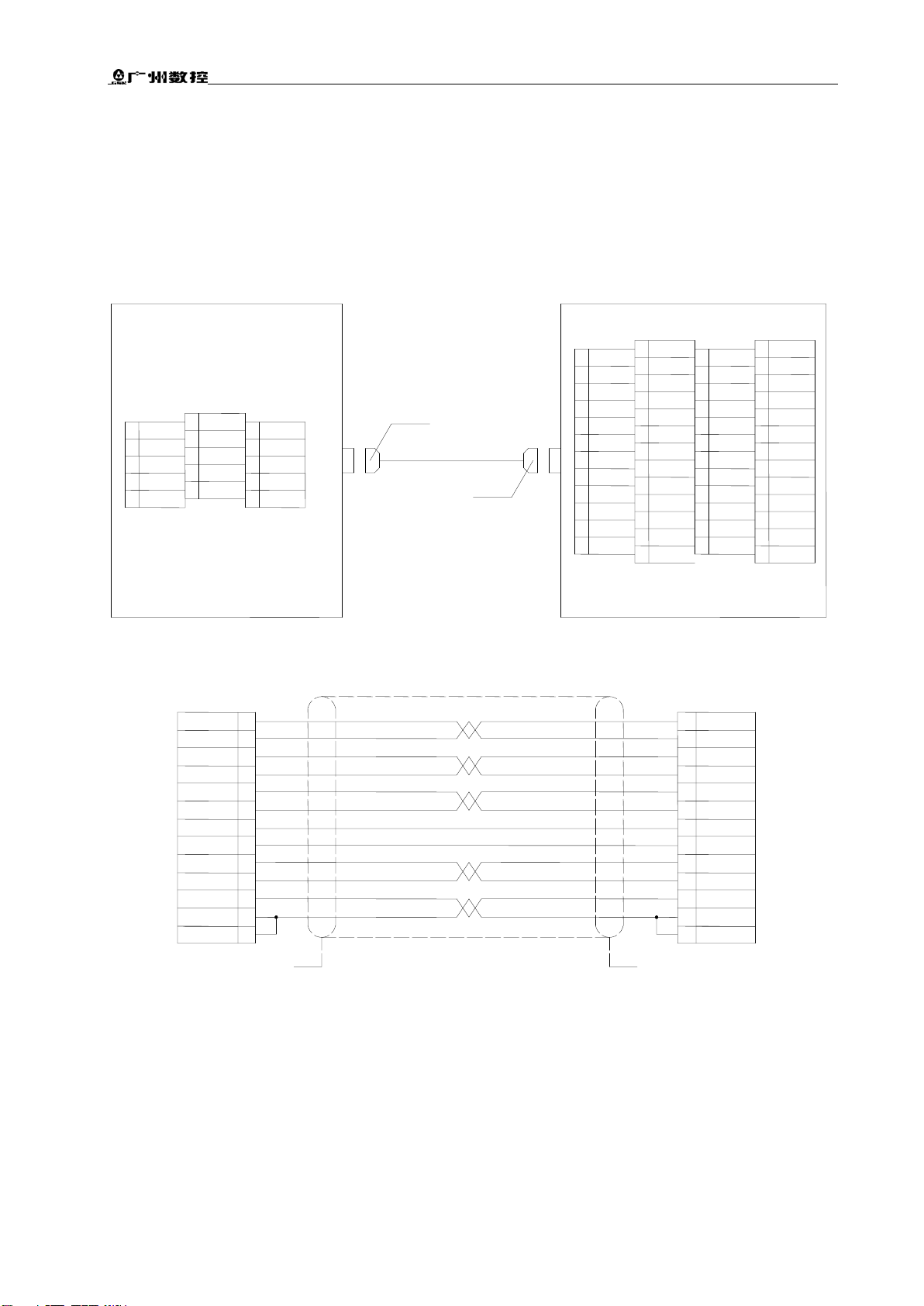
3.Connection between NC Unit and GS2000T-CA1 Drive Unit.....................................................5
(without brake) ...............................................................................................................................5
4. Connection between NC Unit and GS2000T-CA1 Drive Unit....................................................6
(with brake)..................................................................................................................................6
5. Full closed-loop connection with Grating Ruler.........................................................................7
6. Connection between NC Unit and DAP03 Spindle Servo Drive Unit........................................8
7. Connection between NC Unit and GS3000Y-NP2 Spindle Servo Drive Unit............................9
8. Connection between NC Unit and Spindle Inverter.................................................................10
9. Machine Tool Operation Panel................................................................................................11
10. Connection between NC Unit and Operation Panel..............................................................12
11. Connection between external MPG and Operation Panel.....................................................13
12. Connection between NC Unit and PC ...................................................................................14
13. Connection Method for Brake and System Power-on Control ..............................................15
14. Connection between NC Unit and I/O Unit............................................................................16
15. General of External I/O Unit (X1) Interfaces..........................................................................17
16. Connectivity Diagrams for I/O Unit (X1) Input/Output Signals ..............................................18
17. I/O Points Definition (X1) .......................................................................................................19
Appendix 1 Installation Dimension Drawings............................................................................23
Appendix 2 Connection between NC Unit and DA98D Drive Unit(obsolete product)..........28
GSK983Ta-H/ GSK983Ta- V Turning CNC System Connection Manual....................................30
Version Upgrading Records.........................................................................................................30