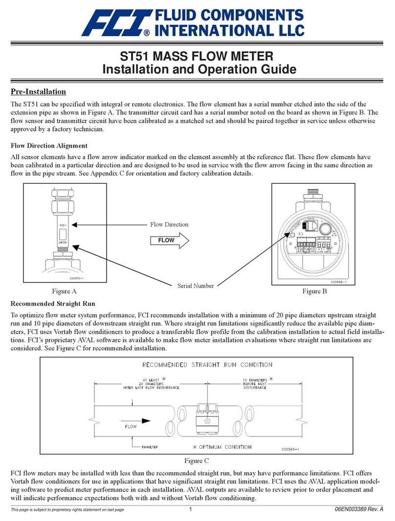
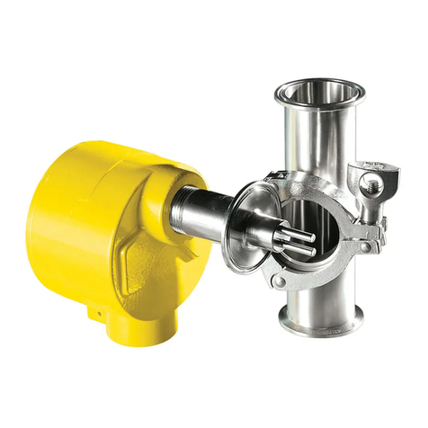
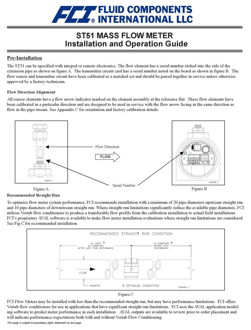
FCI MT86 Instruction manual

Doc. No. 003162 Rev. G

003162 Rev. G MT86/MT86HT Flow Meter
ii Fluid Components International LLC
Notice of Proprietary Rights
This document contains confidential technical data, including trade secrets and proprietary information which is the property of Fluid Components
International LLC (FCI).Disclosure of this data to you is expressly conditioned upon your assent that its use is limited to use within your company
only (and does not include manufacture or processing uses). Any other use is strictly prohibited without the prior written consent of FCI.
© Copyright 2013 by Fluid Components International LLC. All rights reserved. FCI is a registered trademark of Fluid Components International LLC. Information subject to change without notice.

MT86/MT86HT Flow Meter 003162 Rev. G
Fluid Components International LLC iii
Table of Contents
1GENERAL .........................................................................................................................................................................................1
Description ........................................................................................................................................................................................1
Specifications....................................................................................................................................................................................2
2INSTALLATION.................................................................................................................................................................................3
Receiving/Inspection.........................................................................................................................................................................3
Packing/Shipping/Returns.................................................................................................................................................................3
Factory Calibration Note ...................................................................................................................................................................3
Pre-Installation Procedure.................................................................................................................................................................3
Install Flow Element..........................................................................................................................................................................4
Install Flow Transmitter.....................................................................................................................................................................5
Power Connection Information..........................................................................................................................................................5
Installation Quick-Check List.............................................................................................................................................................8
3OPERATION .....................................................................................................................................................................................9
Introduction .......................................................................................................................................................................................9
Enable Optional Totalizer Back-up Battery .......................................................................................................................................9
Apply Power....................................................................................................................................................................................10
Operator Interaction ........................................................................................................................................................................10
Non-Zero Based Calibration............................................................................................................................................................10
Zero Based Calibration ...................................................................................................................................................................10
Delta "R" Table................................................................................................................................................................................11
Generating New Delta "R" Tables...................................................................................................................................................11
New Calibration Procedure (in field) ...............................................................................................................................................12
4MAINTENANCE ..............................................................................................................................................................................17
Introduction .....................................................................................................................................................................................17
Maintenance....................................................................................................................................................................................17
5TROUBLESHOOTING ....................................................................................................................................................................19
Quick-Check Troubleshooting.........................................................................................................................................................19
Troubleshooting Equipment ............................................................................................................................................................19
Non-Maintenance Observations......................................................................................................................................................19
Troubleshooting Process ................................................................................................................................................................20
Troubleshooting Process - Voltage Measurements ........................................................................................................................22
Troubleshooting Process - Flow Element Current ..........................................................................................................................25
Field Calibration Techniques...........................................................................................................................................................25
Calibration Verification Procedure (Using Decade Boxes)..............................................................................................................26
Calibration Verification Procedure (Using an FC81 Field Calibrator)..............................................................................................27
Switch Point Calibration Procedure.................................................................................................................................................28
Switch Point Verification Procedure................................................................................................................................................29
Analog Output Test Procedure........................................................................................................................................................29
Check Procedure for Totalizer and Rate Display............................................................................................................................29

003162 Rev. G MT86/MT86HT Flow Meter
iv Fluid Components International LLC
Check Procedure for Flow Meter Displays with Zero and Non-Zero Based Calibration .................................................................30
Defective Parts................................................................................................................................................................................33
Customer Service............................................................................................................................................................................33
APPENDIX A DRAWINGS.................................................................................................................................................................35
APPENDIX B GLOSSARY..................................................................................................................................................................39
APPENDIX C CUSTOMER SERVICE ................................................................................................................................................41
APPENDIX D CE CONFORMANCE...................................................................................................................................................47
APPROVED CE MARKING CONFIGURATIONS...........................................................................................................................47
CONDITIONALLY APPROVED CE MARKING CONFIGURATIONS............................................................................................47
INSTALLATION CONFORMITY CRITERIA....................................................................................................................................47
LOCATION OF CE MARK DOCUMENTATION..............................................................................................................................48
List of Figures
Figure 1 –Cut-Away View of One Sensing Point ......................................................................................................................................1
Figure 2 –Flow Element Showing Flat Area, Flange Mount Shown..........................................................................................................4
Figure 3 – MT86 or MT86HT Wiring Diagram...........................................................................................................................................7
Figure 4 – GF90 Flow Element With Optional Isolator Module.................................................................................................................7
Figure 5 –Isolator Output Module .............................................................................................................................................................8
Figure 6 –Battery Jumper and Reset Locations........................................................................................................................................9
Figure 7 – Zero Based Calibration..........................................................................................................................................................11
Figure 8 –Zero and Span Adjustment.....................................................................................................................................................14
Figure 9 – A/D Data Sheet......................................................................................................................................................................15
Figure 10 – Terminal Plug.......................................................................................................................................................................21
Figure 11 – Electrical Assembly Layout..................................................................................................................................................23
Figure 12 – Control Board Layout...........................................................................................................................................................24
Figure 13 – Decade Box Wiring Diagram ...............................................................................................................................................27
Figure 14 - Input Board ...........................................................................................................................................................................32
List of Tables
Table 1 – Interconnecting Cable Minimum Conductor Size (Maximum AWG Number)............................................................................6
Table 2 – Jumper Configuration For Output Adjustment ........................................................................................................................13
Table 3 – Quick Check Troubleshooting.................................................................................................................................................19
Table 4 – Terminal Plug Resistances .....................................................................................................................................................21
Table 5 – Power Supply Voltages, Power Supply Board ........................................................................................................................22
Table 6 – Power Supply Voltages, Control Board...................................................................................................................................22
Table 7 – Input Board Terminal Voltage Check......................................................................................................................................25
Table 8 – Current Measurements ...........................................................................................................................................................25
Table 9 – Totalizer Decimal Point Position .............................................................................................................................................30
Table 10 - Components for 100 and 1000 Ohm Flow Meters.................................................................................................................31
Table 11 - Recommended Spare Parts ..................................................................................................................................................32
Table 12 - Recommended Special Test Equipment ...............................................................................................................................32

MT86/MT86HT Flow Meter GENERAL
Fluid Components International LLC 1
1 GENERAL
Description
The MT86 and MT86HT is an air and gas mass multipoint flow meter that incorporates one or more flow elements connected to a flow
transmitter. Together they are designed to measure the mass flow in pipes, ducts or stacks. The flow meter accurately measures the
irregular flow profiles. An MT86 or MT86HT measures flow from up to eight individual sensing points. An average of the individual flow
signals gives an output signal that represents the total mass flow. This output signal operates up to four different output modules of choice.
Operating Principles
The flow meter has flow elements containing sensing points that are connected to the flow transmitter (control circuit boards) by a wiring
harness. The flow elements and the flow transmitter are usually separated by some distance that in some cases can be up to 1000 feet
(300m). The output that comes from the flow transmitter goes to the customer's applications, such as valve control circuitry, alarms or
meters. The operational theory of the flow element sensing points and the flow transmitter are discussed below.
Flow Element
The flow element consists of 2 to 8 sensing points. Each sensing point has two pairs of thermowells (metal tubes) of the same size and
shape. Each pair of thermowells is welded together. One thermowell pair has a heating element placed in one tube and an active
Resistance Thermal Detector (RTD) placed in the other tube. The other thermowell pair has a reference RTD placed in one tube and an
empty thermowell tube that is for mass equalization. See Figure 1for a cut away view of one sensing point.
The two pairs of thermowells are physically separated by a distance that allows the process media to flow between them and yet prevents
thermal interaction between the two pair, see Figure 1below.
Figure 1 –Cut-Away View of One Sensing Point
Flow Transmitter
Each sensing point is connected to a separate flow transmitter circuit. The basic functions of the flow transmitter are to provide power to
the flow element, measure the temperature differential (∆T) between the two RTDs as a function of resistance, amplify and linearize the
resistance differential (∆R) measurement of the flow element input signal and to provide an output signal. The linearized signals from the
sensing points are then averaged together and converted into the final output signal (4-20 mA, 0-5 VDC, 0-10 VDC, etc.) as specified by
the customer.
The flow transmitter has a diagnostic alarm. If a problem exists with a sensing point, a Light-Emitting-Diode (LED) on the control board
flashes to notify the customer.
REFERENCE RTD
MASS EQUALIZING
HEATER
ACTIVE RTD
C00124-1-2
TUBE
FLOW

GENERAL MT86/MT86HT Flow Meter
2 Fluid Components International LLC
Specifications
• Process connection:
2-inch male NPT or 2-inch 150-lb. raised-face carbon steel
flange.
• Number of sensing points:
Up to 8 sensing points.
• Insertion length:
The duct dimensions at the measurement site determine the
insertion U-length.
• Material of construction:
All wetted parts are 316 stainless steel with nickel braze filler
per AMS 4777.
• Local enclosure:
NEMA 4X enclosure with 1 inch female NPT connection ports,
stainless steel, QDC connector.
• Remote enclosure:
NEMA 4X enclosure. Flow elements are equipped with 8-
conductor, 22
A
WG, Kapton insulated foil shielded cable.
• Operating pressure:
Standard MT86 is 0-50 PSIG, or higher depending on
application.
• Operating temperature:
Standard flow element: -50 to 350 °F (-46 to 177 °C).
High temperature (HT) element: -50 to 850 °F (-46 to 454 °C).
Flow transmitter: 0 to +150°F (-18 to 66 °C) with LCD or -50 to
150 °F (-46 to 66 °C) without LCD.
• Flow range:
0.25 to 150 fps in gas under standard conditions (14.7 PSIA @
70 °F).
• Flow element assemblies:
May have 1, 2, 3 or 4 separate flow element assemblies. Must
contain a minimum of 2 sensing points per flow element.
• Input power:
Standard: 100-130 VAC or 200-270 VAC, 50/60 Hz,
50 watts maximum.
Optional: 18-36 VDC, 50 watts max.
• Output signal:
4-20 mA current loop capable of driving a 1000-ohm load.
Optional:
10-50 mA, 400 ohm load max.
0-5 VDC, 2 mA current max.
1-5 VDC, 2 mA current max.
0-10 VDC, 2 mA current max.
• Interconnecting cable:
24 AWG (minimum) 8-conductor shielded cable with PVC
insulation (100 feet maximum). Longer distances are possible
using a heavier gauge wire for the heater circuit. See Table 1,
page 6, for more information.
• Turn down ratio:
2:1 to 100:1 within flow element range customer specified.
• Accuracy:
±3% of full scale at the temperature of calibration; ±5% of full
scale with temperature compensation over a range spanning
200°F. Manufacturer determines the accuracy for specific duct
configurations upon submittal of a fully completed multipoint
mass flow meter application data sheet.
• Repeatability:
±1% of full scale.
• Approvals:
F.M., C.S.A., and CENELEC approvals are available for all MT
series multipoint mass flow meters.
Options
Enclosures:
Explosion-proof NEMA 7 electrical enclosure is available for
both the flow element and flow transmitter that complies with
NEC Code, Class I, Divisions 1 & 2, Groups C & D; Class II,
Divisions 1 & 2, Groups E, F, & G.
• Flow display indicators:
• 3½-digit Flow Rate Display.
• 8-digit Flow Totalizer Display.
• Available outputs (up to four module circuit boards):
Switch point: DPDT relay at 2 or 10 Amp, 115 VAC.
Current loop, 4-20 or 10-50 mA.
Analog voltage output: 0-5, 0-10, or 1-5 VDC.
Remote sensor diagnostic alarm: SPDT relay, 6A at 115 VAC.
• Rate limit board:
Permits adjustment of the rate of change of the output signal
with respect to the rate of change of the input signal. This option
is used when the measured flow is fluctuating and a stable
output signal is needed.
• Mass-to-volume converter:
Changes the mass flow signal to a signal representing actual
cubic feet per minute or feet per second (actual velocity).
• Accessories:
The FES-200 flow element simulator simplifies verification of the
MT86/MT86HT in the field. This device provides the variable
resistance required to input a Delta "R".

MT86/MT86HT Flow Meter INSTALLATION
Fluid Components International LLC 3
2 INSTALLATION
Receiving/Inspection
• Unpack carefully, observe Electro-Static Discharge (ESD) precautions if handling the flow transmitter.
• Inspect for damage to the flow element and the flow transmitter.
• Verify that all items in the packing list were received and are correct.
• Verify the Delta R data sheet and the Instrument Information Sheet are present in the plastic page protector found in the back of the
manual.
If the above items are satisfactory then proceed with installation. If not, then stop and contact the FCI customer service representative for
instructions.
Packing/Shipping/Returns
These issues are addressed in APPENDIX C, page 35.
Factory Calibration Note
The flow meter is factory calibrated to the flow range specified in the order. There is no need to perform any verification or calibration steps
prior to installing and placing the flow meter in service.
Pre-Installation Procedure
Warning: Install the flow meter with qualified personnel only. Perform the installation according to the
current edition of the National Electrical Code. Ensure that all power is OFF. Any instances where
power is to be applied to the flow meter will be noted in this manual. Where the instructions call
for the use of mains power, the operator assumes all responsibility for conformance to safety
standards and practices.
Caution:
The flow meter is not designed for weld-in-place applications. Never weld to process connection
or a structural support.
Damage resulting from moisture penetration of the local or remote enclosure is not covered by
product warranty.
The flow transmitter contains electrostatic discharge (ESD) sensitive devices. Use standard ESD
precautions when handling the flow transmitter. See below for ESD details.
Use Standard ESD Precautions
Use standard ESD precautions when opening an instrument enclosure or handling the flow transmitter. FCI recommends the use of the
following precautions: Use a wrist band or heel strap with a 1 megohm resistor connected to ground. If the instrument is in a shop setting
ensure there are static conductive mats on the work table and floor with a 1 megohm resistor connected to ground. Connect the instrument
to ground. Apply antistatic agents to hand tools to be used on the instrument. Keep high static producing items away from the instrument
such as non-ESD approved plastic, tape and packing foam.
The above precautions are minimum requirements to be used. The complete use of ESD precautions can be found in the U.S. Department
of Defense Handbook 263.
Verify Serial Numbers
Verify that the local enclosure, remote enclosure and flow transmitter serial numbers match.
When multiple local enclosures are connected to one remote enclosure, each local enclosure serial number has a suffix that represents the
flow element number. For example, if two local enclosures are connected to a remote enclosure, the local enclosure will have a base serial
number of 123. The first local enclosure would have the serial number 123-1 and the second local enclosure would have the serial number
123-2.

INSTALLATION MT86/MT86HT Flow Meter
4 Fluid Components International LLC
Prepare or Verify Flow Element Location
The flow element location has been previously determined before the time of order. Mounting the flow element in a position different than
originally determined may cause reading errors.
The shape of the flow element is cylindrical with a diameter of 2.00 inches (50.8 mm). The flow element length (U-length) is customer
specified. The recommended diameter for the clearance hole needed to mount the flow element is 2.16 inches (54.8 mm).
For the best performance, prepare an additional support for flow elements that are longer than 2 feet (61 cm). Refer to APPENDIX A, page
35, for specific information.
Verify Dimensions
Verify the customer specified flow element U-length and instrument mounting interface dimensions are correct for the application. Compare
the instrument hardware, APPENDIX A, page 35, and the process interfaces for fit.
Verify Flow Direction for Flow Element Orientation and Placement
The flow element comes with a flat surface machined on the flow element near the enclosure. This flat surface is known as the Reference
Flat and includes a flow arrow etched on its surface to indicate flow direction. See Figure 2for details.
Figure 2 –Flow Element Showing Flat Area, Flange Mount Shown
Align the flow element so the flat is parallel to the direction of flow. Also, align the flow arrow to point in the direction of flow. Failure to
correctly install the flow element reduces the accuracy of the flow meter. Refer to APPENDIX A, page 35, for specific information.
Install Flow Element
Install the flow element for the type of process connection used. If applicable, connect the end of the flow element to a recommended
mechanical support. See APPENDIX A, page 35, for installation details. The following are general steps for flow element installation.
Threaded Mount
Note:
When mounting the flow element, use a lubricant or sealant applied to the male threads of all
NPT connections. Ensure that the lubricant or sealant is compatible with the process
environment. Make sure all the process connections are tight. To avoid leaks do not over tighten
or cross-thread the connections.
VERTICAL
FLOW
APPLICATIONS
FLOW
HORIZONTAL
APPLICATIONS
C00277-1-1
NOMENCLATURE
ORIENTATION FLAT
PER APPLICATION
FLOW DIRECTIONARROW
FLOW"
PARALLEL TO
"THIS SURFACE
SENSING ELEMENT NUMBER

MT86/MT86HT Flow Meter INSTALLATION
Fluid Components International LLC 5
1. Verify end hardware is loose if present. Carefully insert the flow element into the process mount. Align the flow element with the end
support if present.
2. Verify that the process media is in the same direction as the flow arrow on the reference flat that is near the local enclosure.
3. The threads are right-handed. Place pipe wrench on un-threaded portion of metal shaft. Rotate until snug and continue to turn until
the reference flat is parallel to the process flow. Apply even pressure so as not to disfigure the nipple.
Caution: Do not apply any leverage to the local enclosure itself.
4. Tighten all connections. Tighten all end hardware if present.
Flanged Mount
1. Verify end hardware is loose if present. Carefully insert the flow element into the process mount. Align the flow element with the end
support if present.
2. Attach the process mating flange with care. Maintain the correct orientation of the flow element to ensure flow meter accuracy.
3. Verify that the flow arrow points in the same direction as the process media flow, and the flat is parallel to flow.
4. Apply the appropriate gasket and/or sealant to the flange mount faces as required.
5. Attach with a bolt, two flat washers, lock washer and nut for each bolt hole; apply lubricant/sealant to male threads and torque. For
correct hardware and torque, refer to ANSI B16.5 specifications.
6. Tighten all of the connections.
Refer to APPENDIX A, page 35, for specific information.
Install Flow Transmitter
Caution:
In applications where the flow element is located in an explosive environment, isolate the conduit before it leaves the
environment. A potting "Y" may be used to provide the isolation.
Note:
FCI recommends installing an AC or DC power disconnect switch and fuse near the flow transmitter to interrupt
power during installation, maintenance, calibration, and troubleshooting procedures.
Remote Hardware
APPENDIX A, page 35, shows the remote enclosure along with physical dimensions to properly mount the flow transmitter. Select a
location for the flow transmitter within 1000 feet of the flow element. Allow enough room for the hardware to be easily accessible and to be
able to open the remote enclosure cabinet door at any time. Secure the flow transmitter solidly to a vertical surface capable of providing
support. Use the appropriate hardware to secure the flow transmitter as required.
Power Connection Information
Conduit Routing
All electrical connections are to be made through the 1 inch NPT opening in the remote enclosure. Run all electrical cables through an
appropriate conduit for the protection of the flow meter and personnel. See Figure 3and Figure 4, page 7, for the specific mechanical
details.
The flow transmitter design requires the power and output conduit to connect with the remote enclosure's left access port and the local
enclosure conduit to connect with the right access port(s).
Protection of the flow transmitter from moisture is important. Keep the entry of the conduit into the enclosures in the downward direction so
condensed moisture that collects in the conduit will not drain into the enclosure. The local enclosure may not be turned more than 180°
using the threads on the enclosure to gain an acceptable orientation. In addition, FCI recommends sealing off the conduit with a potting Y
or other sealing method to prevent moisture from entering the enclosures.
Minimum Wire Size
Table 1below shows the smallest (maximum AWG number) copper wire which can be used in the electrical cables. Use a lower gauge of
wire for less of a voltage drop. Contact FCI concerning greater distances than those listed in the chart.

INSTALLATION MT86/MT86HT Flow Meter
6 Fluid Components International LLC
Table 1 – Interconnecting Cable Minimum Conductor Size (Maximum AWG Number)
Connection
Maximum Distance for AWG
10 ft. (3m) 50 ft. (15m)
100 ft. (31m)
250 ft. (76m)
500 ft.
152m)
1000 ft.
(305m)
AC Power
22
22
22
20
18
16
Relay (2A)
28
22
20
16
12
10
Relay (10A) 22 16 12 8 6
Not
Recommend
Flow Element Wires*
24
24
24
22
22
18
*Note: Requires a shielded cable. The shield is connected to the GND pin of TS_ of the input board. The
other end of the shield is left floating (no connection to the flow element enclosure).
The standard cable provided is 22 AWG. Refer to APPENDIX A, page 35, for specific information.
Flow Transmitter Wiring Connections
See the wiring diagrams in Figure 3or Figure 4, page 7, for the flow element wiring to the input boards. Run separate excitation and sense
wires for the Active, Reference, and Ground connections. The flow meter will not operate properly without these connections. If the Active
and Reference wires are reversed the flow meter will output incorrect flow rates. Use shielded cable with all signal applications. Connect
the shield to the input board only and not to the flow element terminal strip. Connect the shield to pin 1 of TS_ on the input board.
The connector for sensing point 1 must be plugged into the innermost connector on the input board which is plugged into P1 of the control
board. Sensing point 2 is connected to the outermost connector of the same input board. Sensing point 3 is plugged into the innermost
connector on the input board which is plugged into P2 of the control board. Sensing points 4 through 8 are plugged in the same manner.
Make the customer connections to the output modules (relay logic, current or voltage).

MT86/MT86HT Flow Meter INSTALLATION
Fluid Components International LLC 7
Figure 3 – MT86 or MT86HT Wiring Diagram
Figure 4 – GF90 Flow Element With Optional Isolator Module
*
*
ISOLATOR 1
+
-
IN
-
+
OU T
+
-
P2
ISOLATOR 2
OU T
+
-
-
+
IN
+
-
P2
mA/VOLT AGE
OUTPUT BD.
mA/VOLT AGE
OUTPUT BD.
*
*
HEATER
ACTIVE
SENSOR
REFERENCE
SENSOR
1
C00126-2-1
HTR-
HTR+
ACT EXC
REF EXC
ACT SEN
REF SEN
GND SEN
GND
POWER SUPPLY
33
3 3
3
3
3
3
3
P1
TS1
OPTIONAL
OUTPUT
MODULES
ELECTRONICASSEMBLY
P7 & 8
P5 & 6
P3 & 4
P1 & 2
CONTROLBOARD
POWER
INPUT TERMINALENCLOSURE
AT SENSORASSEMBLY
(TYPICAL WIRING FOR
ONE SENSE POINT)
8- OR 16-CONDUCTOR
CABLE SHIELDED
DUALHEAD INPUT BOARD
1
CUSTOMER CONNECTIONS.
OPTIONALOUTPUT MODULES:
1. TROUBLE INDICATOR BD: 6 AMPSPDT RELAY.
2. SWITCHPOINT BD: 2 AMPOR 10 AMPDPDT RELAY.
3. MILLIAMPDRIVER BD: 4-20 mAOR 10-50 mA.
4. VOLTAGE OUTPUT BD: 0-5, 1-5, OR 0-10 VDC.
CUSTOMER SHOULD GROUND OUTPUT NEG ATIVE AT CIRCUIT BD.
3
2
2
2
2
2
N/O B
POLE B
N/C B
N/O A
POLEA
N/C A
OUT +
OUT -
N/C
POLE
N/O
A.C. GND
A.C. NEUT
A.C. LINE
D.C.+
D.C.-
GND
CHASSIS
OPTIONAL
24 VDC INPUT
TS8
TS7
TS6
TS5
TS4
TS3
TS2
TS1
CONN NO.
4
8
7
6
5
HEAD NO.
3
2
1
BOARD
CONTRO L
mA/VO LTAGE
OUTPUT BD.
OUTPUT BD.
mA/VO LTAGE
IN
OUT
ISOL ATOR 1
OUT
ISOL ATOR 2
IN
GND SEN
GND
SHIELD
REF EXC
ACTEXC
HTR+
REF SEN
ACTSEN
(HEAD 1)
TS1
(HEAD 2)
TS2
HTR- 1
FLOW ELEMENT
ACTIVE SENSOR
HE ATER
REFERENCESENSOR
(IN LOCA L ENCLOSURE)
TERMINA L BLOCK
5
4
2
3
GND SEN
ACTEXC
REF SEN
ACTSEN
REF EXC
HTR-
HTR+
GND
N/C
OUT +
OUT -
N/C B
POLE B
N/O B
N/C A
POLE A
N/O A
POLE
N/O
ELECTRONIC ASSEMBLY
A.C. LINE
A.C. NEUT
A.C. GND
OPTIONAL
D.C. +
D.C. -
GND
CHASSIS
24VDC INPUT
OPTIONAL
OUTPUT
MODULES OPTIONAL
4-20 mA OUTPUT ISOLATOR MODULES
4 BOTH SENSE AND EXCITATION WIRES MUST BE RUN BETWEEN
THE SENSOR AND THE CIRCUIT BOARD FOR CORRECT OPERATION.
5 ALL WIRES ARE MARKED PER TERMINATION.
CUSTOMER CONNECTIONS
*
FLOW ELEMENT
(HEAD 2 SHOWN)
1 TROUBLE INDICATOR BOARD: 6 AMP SPDT RELAY.
2 SWITCH POINT BOARD: 2 AMP OR 10 AMP DPDT RELAY.
3 MILLIAMP DRIVER BOARD: 4-20 mA OR10-50 mA.
4 VOLTAGE OUTPUT BOARD: 0-5, 1-5, 0-10 VDC.
2OPTIONAL OUTPUT MODULES:
3INDICATES CUSTOMER CONNECTIONS.
1CUSTOMER SHOULD GROUND OUTPUT NEGATIVE AT CIRCUIT BOARD OR AT RECEIVER
*
C00905-1-1

INSTALLATION MT86/MT86HT Flow Meter
8 Fluid Components International LLC
Input Power
Warning: The output terminals are not power isolated with use of 24 VDC as a power source.
Note: Before inserting the cable core into the terminal strip connector, first turn the terminal screws 10
turns counterclockwise. If this is not done, there is a possibility of inserting the wires between the
top half of the clamps and the frames instead of between the two clamp segments.
FCI strongly recommends installing an AC line disconnect switch (and possibly a fuse) between the power source and the flow meter. The
line switch is an easy way to remove power for calibration and maintenance procedures. Also the line switch is an added safety feature.
100 VAC, 115 VAC, 230 VAC or 24 VDC is the power source for the flow meter (use only one power source). Wire the power directly to the
power supply terminal strip TS1.
Isolated Output Option and 4-20 mA Adjustment
An isolated 4 to 20 milliampere (mA) output is an available option. The isolated output is available by connecting a loop powered isolator
module to the transmitter output. Figure 5shows the isolator output module. The module has its own set of output terminals which provide
an isolated 4 to 20mA output equal to the non-isolated instrument output. This one-to-one current isolation is used to prevent
instrumentation ground loops. See Figure 3or Figure 4, page 7, for the appropriate wiring diagram to install the isolated output module.
Use of the isolator module will add a small signal conversion error to the instrument output and limit the output load to 350 ohms. The
module must be adjusted in the field to the specific customer load. A red LED on the module indicates when loop power is applied.
1. Connect the customer load with a milliampere meter in series with the output terminals of the isolators.
2. Connect a milliampere meter in series with the input terminals.
3. Apply power to the instrument. Initiate a full process media flow. Allow a 10 minute warm-up period.
4. Adjust the isolator output span potentiometer (see Figure 5below for placement) so both of the milliampere meters read the same.
5. This completes the output isolator setup. Turn off the power, remove the milliampere meters and reconnect the wiring.
Figure 5 –Isolator Output Module
Installation Quick-Check List
1. Verify that serial numbers match.
2. Properly orient the flat and flow arrow.
3. Ensure there are no leaks at the process connection.
4. Verify that the wiring is properly connected per the wiring diagram.

MT86/MT86HT Flow Meter OPERATION
Fluid Components International LLC 9
3 OPERATION
Introduction
The flow meter has been configured and calibrated to custom specifications. Each flow meter contains distinct operating limits and units of
measurement. This section will show how to determine and manipulate the configuration of the flow meter.
Caution:
The flow transmitter contains electrostatic discharge (ESD) sensitive devices. Use standard ESD
precautions when handling the flow transmitter. See INSTALLATION, page 3, for ESD details.
Enable Optional Totalizer Back-up Battery
There is a totalizer option for the flow meter. This option has a backup battery that keeps power applied to the memory that holds the
accumulated count during loss of power. There is a jumper on the back of the totalizer and display board that needs to be repositioned to
the ON position. See Figure 6for the jumper location. The estimated life of the battery is 3 years of power off operation. The battery power
is drained only when the operating power is off and the battery power is on. During shipment and storage, the battery jumper is OFF to
conserve power.
The flow totalizer accumulates the total quantity of media that has passed the flow element over a specific time. Short two connector
terminals together on the display board to reset the flow totalizer display, see Figure 6below for details. In applications where the operator
is required to reset zero, FCI recommends that these terminals be brought out to a convenient reset switch.
Figure 6 –Battery Jumper and Reset Locations
CONNECTSTO
C00312-1-2
RIBBON CABLE
CONTROLLER BOARD
RESET
BATTERY
TB1
OFF
ON
TOTALIZER AND DISPLAY BOARD (OPTIONAL)

OPERATION MT86/MT86HT Flow Meter
10 Fluid Components International LLC
Apply Power
Warning:
When an open flow meter has power applied, the operator assumes all responsibility for conformance to safety
standards and safe practices.
Verify the wiring, then apply power to the flow meter. There are no special instructions for shutdown of the flow meter; just remove the
operating power.
Wait a minimum of 10 minutes for flow meter to stabilize. The output signal indicates the media flow. There is no operator action needed
because the flow meter operates from the factory settings.
If the output signal is zero, is out-of-range for the expected values or is obviously not right then turn off the power and go to
TROUBLESHOOTING, page 19, to find the problem.
Operator Interaction
There is little need for interaction between the operator and flow meter. The flow meter is fully automatic when it operates in the normal
monitor mode. FCI advises the use of factory default settings that the flow meter was ordered with. Do not reset the flow meter's operating
values by trial and error.
A calibration table can be found in the back of this manual. The table shows a listing of the actual mass flow values as indicated by the
output signal. For example: using the standard 4-20 mA output signal, if the signal is 12.0 mA, find 12.0 in the milliamp row and read
across to the next column for the measured flow.
The output signal provides an instant readout of mass flow. The output signal shows only the flow rates between the upper and lower limits
of the calibrated range. For zero-based instruments the output signal will show zero whenever the flow rate is below the calibrated lower
limit. For non-zero-based instruments the output signal will read the minimum specified flow rate.
The flow totalizer accumulates the total quantity of media that has passed the flow element over a specific time.
Short two connector terminals together on the display board to reset the flow totalizer display, see Figure 4 for details. In applications
where the operator is required to reset zero, FCI recommends that these terminals be brought out to a convenient reset switch.
Non-Zero Based Calibration
This is a factory preset item.
In a non-zero based calibration, the low-limit output signal (4 mA) is equal to the minimum calibrated flow. The minimum calibrated flow is a
value greater than zero. The flow meter's output signal indicates the low-limit flow signal (4 mA) from zero flow up to the low-flow limit
parameter. Use a non-zero based calibration when the minimum flow rate does not approach zero and the turndown ratios are small.
At no-flow, the output signal will indicate the minimum calibrated flow.
Zero Based Calibration
In a zero-based calibration, the slope of the output signal is shifted so the low-limit flow output signal (4 mA) is equal to zero flow. See
Figure 7for details. Flow meters cannot measure zero flow accurately. The flow meter reads out the low-limit signal (4 mA) from zero flow
up to the minimum calibrated flow. Then the output signal steps up to the proper signal value of the mass flow.

MT86/MT86HT Flow Meter OPERATION
Fluid Components International LLC 11
Figure 7 – Zero Based Calibration
The output signal is easier to interpolate when milliamp output is interfaced with control room 0 to 100% gauges; 50% of the signal will
correspond to 50% of the maximum flow rate.
Zero-based flow meters have less signal to resolve over full scale. A zero-based flow meter with a turndown ratio of 10:1 will have 10%
less output range to resolve flow (5.6 mA to 20 mA instead of 4 mA to 20 mA in a non-zero-based flow meter).
Zero-based calibration is the factory default.
Delta "R" Table
The Delta R Sheet (found in the plastic page protector in the back of this manual) contains the actual data chart for the flow meter. The
Delta R portion of this sheet relates actual laboratory calibration measurement points of the differences (delta) between the reference and
active RTDs at certain flow rates.
These parameters are used at the factory to determine the linearization coefficients (parameters) over the flow range in question to correct
for non-linearity. The corresponding current and voltage output readings are also shown (again at factory default settings), changes to
range and zero will only affect the output signals. Flow versus Delta R relationship is fixed for a given set of flow elements; do not change
the coefficients except in special circumstances as the overall accuracy of the system is tied to these numbers. Call Customer Service if
there is a problem in this area.
The Calibration Table is a printout (at factory default settings for zero and offset) of the relationship of displayed mass flow readings related
to the current output when calculated over the entire flow range using the fitting equation and its respective coefficients.
Generating New Delta "R" Tables
Using the FC81 Calibrator
1. Obtain the correct FC81 Field Calibrator for the MT86 or MT86HT Flowmeter:
Model FC81-8 is used for the MT86 with 1000 ohm flow element sensing point RTDs.
Model FC81-7 is used for the MT86HT with 100 ohm flow element sensing point RTDs.
2. Turn the operating power OFF and then disconnect the flow element cable from the terminal block TS1 on the input board.
3. Connect the FC81 Field Calibrator cable to terminal block TS1 (sensing point 1). Also, connect the cable to one of the output module
connectors P7, P8, P9, or P11 that is located on the control board. A set of precision decade boxes can be used instead of the FC81
Field Calibrator. Use the wiring diagram in Figure 13 to connect the decade boxes.
4. On the control board, monitor the voltage (VDC) across TP10 (-) and TP9 (+) and from TP5 (-) to J8 (+).
5. On the output board, monitor the output signal (4 to 20 mA, 10 to 50 mA, 0 to 5 VDC, etc.,) with a DMM.
C00114-3-2
ZERO BASED
ZERO
OUTPUT
(mA)
MIN
FLOW
50% FULLSCALE
NON ZERO BASED
FLOW (SFPS)
0
0.0
4.0
8.0
12
16
20
10 20 30 40 50 60

OPERATION MT86/MT86HT Flow Meter
12 Fluid Components International LLC
6. Close switch SW1-3 that puts the flow transmitter in the manual mode; this enables the head-select switch SW2 to select and monitor
one sensing point.
7. Set the head-select switch SW2 to the number one (1) position.
8. Verify that switch SW4 is in the OP (OPerate) position.
9. Turn the operating power ON and let the system stabilize for a minimum of 5 minutes.
10. Set the FC81 Field Calibrator to the "READ VOLTS" position and remove the "ADD OHMS" by setting both buttons to the OUT
position. The voltage on the FC81 Field Calibrator can now be read. This is the same voltage that is across TP5 (-) and J8 (+). Adjust
the voltages by turning the "OHMS ADJUST" potentiometer.
11. On a blank Delta "R" sheet, write down the serial number of the flow meter and the flow element serial number.
Blank Delta "R" sheets are obtained from FCI Customer Service.
12. Adjust the "OHMS ADJUST" potentiometer to give an output of 4.00 mA, which is zero volts on the FC81 Field Calibrator.
13. On the Delta "R" sheet record the TP9 to TP10 voltage, the TP5 to J8 voltage (which is the same voltage that the FC81 Field
Calibrator displays), the MILLIAMP OUTPUT and the LOCAL DISPLAY reading, if applicable.
14. Depress the "SET OHMS" button on the FC81 Field Calibrator to display the new Delta "R" value for the 4.00 mA output. With the
FC81 Field Calibrator "SET OHMS" Button depressed the flow meter does not read the Delta "R" values. The DMMs will give open
circuit or random values.
15. Record the new Delta "R" on the data sheet. For the model FC81-8 Field Calibrator the displayed Delta "R" value is divided by 10 .
For the model FC81-7 there is no division necessary.
16. Set the calibrator to "READ VOLTS" and then adjust the "OHMS ADJUST" potentiometer to give the following outputs: 5.00, 6.00,
8.00, 12.00, 16.00, and 20.00 mA and repeat Steps 13 through 16 for each.
17. Turn the operating power OFF. Then transfer the FC81 Field Calibrator cable to terminal block TS2.
18. Turn the operating power ON. Allow one minute for the flow meter to stabilize.
19. Set the calibrator to "Read Volts" and repeat Steps 10 through 16. Remember to set the head-select switch, SW2, to the number 2
position for sensing point number 2.
20. Repeat this procedure for all the remaining sensing points in the system. Remember to set the head-select switch SW2 to the sensing
point number that a new Delta "R" table is generated for.
21. When the Delta "R" table has been completed for the whole system, set the head-select switch to the total number of sensing points
in the system. For example, a flow meter that has 4 sensing points should have the head-select switch SW2 in position 4.
22. Open switch SW1-3, which places the flow transmitter in the automatic mode. This puts the flow meter back into the operation mode.
New Calibration Procedure (in field)
Note: The flow meter is calibrated for use with specific customer applications and flow ranges. There may be cause in the
field to readjust the calibration to meet the field data or applications.
A flowmeter EPROM stores data to accommodate a range expansion of up to 25% above full range. If any changes are performed a new
Delta "R" table will be needed to represent the adjustment. If an output adjustment is made, properly record the data and make it available
for FCI records.
The flow meter has a method for changing the span and zero adjustment in the field without losing the original factory setting. The factory
set span and zero will have jumpers J1, J5 and J7 installed, see Figure 12 for the electrical assembly layout. FCI recommends making a
new “Delta R” table after any adjustment are made to the output. Once an adjustment is made the original Delta "R" table does not
represent the changes made.
Span Adjustment Only
The true flow rate of the process flow and the indicating milliamp output of the flow meter must be known before going on with the following
adjustment procedure. Record and have the information available for FCI to review.
To justify a span adjustment only, ensure the flow rate to be above 60% of full scale. Do not perform a span adjustment if the data obtained
is at a flow rate below 40%.
The following procedure is for sensing point (head) number one (1), but any sensing point can be used. The sensing point number that is
selected must match the head number selected at the head-selector, switch SW2.

MT86/MT86HT Flow Meter OPERATION
Fluid Components International LLC 13
1. Record the true flow of the process media and the flow meter's milliamp output.
2. Turn the operating power OFF.
3. Connect the FC81 Field Calibrator to sensing point number 1. A set of precision decade boxes can be used instead of an FC81 Field
Calibrator. For the decade box wiring diagram refer to Figure 13. Model FC81-8 is used for the MT86 with 1000 ohm flow element
sensing point RTDs.
Model FC81-7 is used for the MT86HT with 100 ohm flow element sensing point RTDs.
4. Close switch SW1-3 that puts the flow transmitter in the manual mode; this enables the head-select switch SW2 to select and monitor
one sensing point. Turn ON the operating power.
5. Adjust the FC81 Field Calibrator, or precision decade boxes, to give the milliamp output that was recorded in Step 1. Record the Delta
"R" that produced this output.
6. Remove jumpers J1 and J7. Add jumpers J2 and J8. This makes the span circuitry active.
7. With the FC81 Field Calibrator still at the Delta "R" from Step 5, adjust the span potentiometer, R16, to the new output as calculated
from the true flow measurement in Step 1.
8. From the Delta "R" table, put in the Delta "R" resistance value that represents the 4.0 milliamp output. Verify that the output has not
been affected by the span adjustment.
9. Turn OFF the operating power. Open switch SW1-3, and position the head-select switch SW2 to the number of sensing points in the
system. This puts the flow meter back in the operation mode.
10. Remove the FC81 Field Calibrator or decade boxes and connect sensing point number 1 to the input board.
Span and Zero Adjustment
As with the span adjustment, field data is also needed to perform adjustments. The information that is needed is the true flow rate and the
indicating milliamp output of the flow meter. Record and have the information available for FCI to review. The procedure is basically the
same as the span adjustment procedure. See Table 2for jumper positions.
Table 2 – Jumper Configuration For Output Adjustment
Mode
Install Jumper
J1 J2 J3* J4 J5 J6 J7 J8
Factory Set Span and
Zero Yes No Yes No Yes No Yes No
Span Only Adjust
Activated No Yes Yes No Yes No No Yes
Span and Zero Activation No Yes Yes No No Yes No Yes
* J3 and J4 will always be in this position unless the factory has authorized option changes.
1. Repeat steps 1 through 5 listed above. Record the Delta "R" that was required to generate the milliamp output for both the low and
high flow rates.
2. Remove jumpers J1, J5 and J7. Add jumpers J2, J6 and J8, to make the span and zero circuitry active.
3. Adjust the FC81 Field Calibrator, or precision decade boxes, to the Delta "R" resistance that represents the low flow milliamp output of
Step 1.
4. Adjust the zero potentiometer, R17, on the control board to give the milliamp output that represents the calculated low flow.
5. Adjust the FC81 Field Calibrator, or precision decade boxes, to the Delta "R" resistance value that represents the high flow milliamp
output from Step 1.
6. Repeat Steps 3 through 5 until the correct milliamp output matches the Delta "R" for the high and low flows.
7. Disconnect the FC81 Field Calibrator or precision decade boxes and reconnect the sensing point to its original input board.
8. Return switch SW1-3 to the open position.
9. Set the head-selector, SW2, to the number of sensing points in the system. The flow meter can be reset to the factory set calibration
with the use of the original jumper setup. The originally installed jumpers are J1, J3, J5 and J7. The above span and zero adjustments
are not in effect when the flow meter is in the original configuration. The factory set calibrations are in control of the flow meter.

OPERATION MT86/MT86HT Flow Meter
14 Fluid Components International LLC
Table 2shows the jumper settings that are needed to make the zero and span adjustments active. Figure 8shows the zero and span
effects on the flow meter.
If only the zero adjust needs to be done, the span and zero jumpers will need to be set. Then proceed with the zero adjustment.
Figure 8 –Zero and Span Adjustment
If a span and zero adjustment cannot be done, the other choice for adjustment is an EPROM replacement. The EPROM stores the data
that represents the calibrated flow rate and the performance curve. FCI can provide a new EPROM with the new data and/or range. The
customer does have to provide FCI with Analog-to-Digital (A/D) information and the flow rate so the EPROM can be made. Look at the
Delta "R" table to get the A/D number. In the Delta "R" table, one column is categorized as Voltage In Non-Linear, [TP9 (+) to TP10 (-)].
Use the following equation to calculate the A/D number for the Non-Temperature Compensated flow meter only. Write down the results in
the chart shown in Figure 9.
A/D = ( [TP9 - TP10 (Vdc)]/2 ) X 5( 4096 )
For the Temperature Compensated flow meter, the A/D equation is:
A/D = [( [TP9 - TP10 (Vdc)]/2 ) X (4096)]/(TC Gain)
TC Gain is a function of the reference temperature. Additional data for the TC Gain is needed. This data is the REF SEN (+) to GND SEN
(-) voltage from terminal block TS#.
Note:
This A/D versus flow information is needed for each flow element sensing point in the flow meter.
FCI strongly recommends that as much data as possible be gathered because the calibration will be only as good as the data supplied.
Once a new EPROM is provided it will need to be installed (see the Repair procedure in TROUBLESHOOTING, page 19) and a new Delta
"R" table generated (see the preceding section for the procedure).
C00137-1
SPAN ADJUSTON POTR16 ZERO ADJUSTON POTR17

MT86/MT86HT Flow Meter OPERATION
Fluid Components International LLC 15
Figure 9 – A/D Data Sheet

OPERATION MT86/MT86HT Flow Meter
16 Fluid Components International LLC
This Page Intentionally Left Blank
This manual suits for next models
1
Table of contents
Other FCI Measuring Instrument manuals
FCI
FCI ST50 Operating instructions

FCI
FCI ST100 series User manual
FCI
FCI ST75 Operating instructions

FCI
FCI ST100 series User manual
FCI
FCI ST100A Series User manual
FCI
FCI ST80 Series Instruction manual
FCI
FCI PETROSENSE PHA-100Plus Setup guide

FCI
FCI ST100 series Mounting instructions

FCI
FCI ST100 series Owner's manual

FCI
FCI MT100 User manual
Popular Measuring Instrument manuals by other brands

Agilent Technologies
Agilent Technologies B1500A Training manual
Hanna Instruments
Hanna Instruments HI 221 instruction manual

Hitachi
Hitachi UG 50Y instruction manual

Flybox
Flybox Omnia57 ALTI-VARIO Installation and user manual

ETAS
ETAS XETK-S16.0 user guide

Meilhaus Electronic
Meilhaus Electronic RedHand Scope user manual

