FCI ST100 series User manual

ST100 Series
Thermal Mass Flow Meter
HART Operation
Manual
Fluid Components International LLC (FCI). All rights reserved.

ST100 Series HART
Fluid Components International LLC
Notice of Proprietary Rights
This document contains confidential technical data, including trade secrets and proprietary information which is the property of Fluid Components International LLC (FCI).
Disclosure of this data to you is expressly conditioned upon your assent that its use is limited to use within your company only (and does not include manufacture or
processing uses). Any other use is strictly prohibited without the prior written consent of FCI.
© Copyright 2015 by Fluid Components International LLC. All rights reserved. FCI is a registered trademark of Fluid Components International LLC. Information subject to change without notice.

Fluid Components International LLC i
ST100 Series HART 06EN003404 Rev. A
Table of Contents
Introduction.......................................................................................................................................................................................................................1
Definition ..........................................................................................................................................................................................................................1
Universal HART Commands ..........................................................................................................................................................................................1
Common Practice HART Commands .............................................................................................................................................................................1
Device Specific Commands...........................................................................................................................................................................................1
EDDL/DD Files...............................................................................................................................................................................................................1
FCI Configurator.............................................................................................................................................................................................................1
Installation........................................................................................................................................................................................................................2
General .........................................................................................................................................................................................................................2
Electrical Wiring............................................................................................................................................................................................................2
Topology and Network Configuration............................................................................................................................................................................4
Operation..........................................................................................................................................................................................................................5
Functional Description...................................................................................................................................................................................................5
Process Data Operation.................................................................................................................................................................................................5
ST100 HART Process Data Organization.......................................................................................................................................................................5
Device Description Files................................................................................................................................................................................................6
Service Data Operation.................................................................................................................................................................................................7
Setting the ST100 for the HART Protocol Operation ....................................................................................................................................................9
ST100 HART Command List ........................................................................................................................................................................................10
ST100 HART Universal Commands.............................................................................................................................................................................10
ST100 HART Common Practice Commands................................................................................................................................................................14
ST100 HART Device Specific Commands....................................................................................................................................................................15
ST100 HART DTM...........................................................................................................................................................................................................20
What is FDT-DTM Technology?...................................................................................................................................................................................20
How it works with the ST100 HART device?..............................................................................................................................................................20
ST100 HART DTM Installation and Setup examples..................................................................................................................................................21
How to get the information through ST100 HART DTM device .................................................................................................................................25
ST100 HART PDM...........................................................................................................................................................................................................28
HART Diagnostics...........................................................................................................................................................................................................32
Technical Characteristics................................................................................................................................................................................................35
Appendix A - Drawings...................................................................................................................................................................................................37
Appendix B - Customer Service / Technical Support .....................................................................................................................................................39

ii Fluid Components International LLC
06EN003404 Rev. A ST100 Series HART
INTENTIONALLY LEFT BLANK

ST100 Series HART
Fluid Components International LLC 1
Introduction
This manual describes the ST100 HART protocol 7.3 features, its operation and configuration. The ST100 can provide up to 4 different process
variables. It provides Flow, Temperature, Flow Totalizer, and Pressure, as outputs. The flow output can be selected as Volumetric, Mass
or Velocity units. The ST102 and ST112 can support up to two flow sensors and provides the average flow of the two sensors in a single output.
This documents is written to be used with all members of the ST100 product family configured with the HART 7.3 communication Protocol.
The HART output is provided through an extension card that is fully integrated into the ST100 instrument.
Denition
Universal HART Commands
A collection of commands that must be supported by all HART compatible devices. The Universal Command Specification establishes the minimum
Application layer support required of all HART devices. The Application layer defines the commands, responses, data types and status reporting sup-
ported by the Protocol.
Common Practice HART Commands
A collection of commands applicable to a wide range of devices. These commands shall be supported by devices whenever possible. The HART Com-
mon Practice Commands enhances interoperability by providing additional standardized, device-independent commands.
Device Specific Commands
Commands defined by the manufacturer according to the need of the Field device. The manufacturer of the Field device controls these commands.
The FCI ST100 family of products has 20 manufacturer specific commands.
EDDL/DD Files
Text files interpreted by the host system. The EDDL file is a file that tells the host what functionality the device (ST100) has, and how the functionality
is invoked. The EDDL also tells the host to do common maintenance functions such as calibration, configuration check status of individual sensors,
change engineering units, etc.
FCI Configurator
A PC software tool that gives access to the ST100 functions and features. It facilitates basic instrument setup and configuration, as well as advance
functions. The FCI configurator can interface through the ST100 USB Service port or the Ethernet Service port.

ST100 Series HART
2 Fluid Components International LLC
Installation
General
For details on the general mounting, placement of sensor head and mounting options see the Basic User Manual, 06EN003400.
Electrical Wiring
Access the wiring terminal block by removing the rear electrical connection cover. This cover can be locked closed by the cover locking screw.
Release the cover locking screw and remove the cover.
Cable access to wiring connections is obtained through one of the four conduit outlets, see Figure 6 below.
Figure 1 - HART Output Wiring Table
The HART connections for the ST100 are located in the back panel. The connector for the HART is P1A; the pins are labeled “CH1” and “RTN 1/2”.
The ST100 HART connections are non- polarized, but polarity needs to be observed for other manufacturer’s devices. Connect the HART bus cable as
noted below. See Appendix A for Channel 1 HART Connections on instruments shippped before April 2012.
Figure 6 - Instrument Wiring
See Appendix A for Channel 1 HART
Connections on instruments shippped
before April 2012.

ST100 Series HART
Fluid Components International LLC 3
Figure 3 - Detail External Power Supply connection for Non-Network
Figure 2 - Detail Internal Power Supply connection for Non-Network
ST100 Series HART
4 Fluid Components International LLC
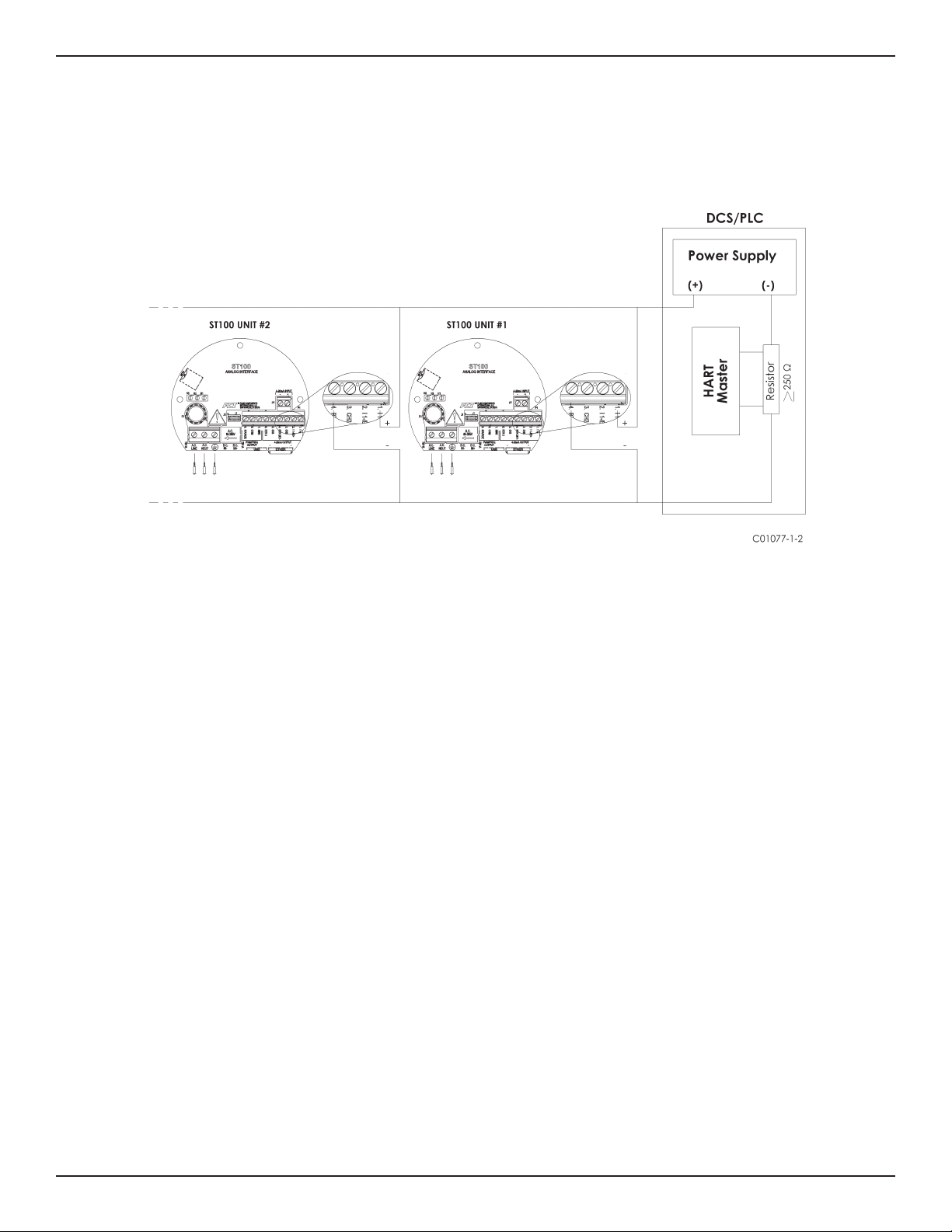
Topology and Network Configuration
The ST100 supports Multidrop topology. In multidrop operation, the devices exchange data and measured values only via the HART protocol/HART
Network. In Network configuration the analog current signal serves just to energize the two-wire devices, providing a current of 4 mA per instrument.
In multidrop mode, up to 15 field devices are connected in parallel to a single wire pair or segment (Figure 4). The host distinguishes the field devices
by their preset addresses that range from 1 to 255. The factory preset address is 0.
Figure 4 - Multidrop Mode with HART Transmitters

ST100 Series HART
Fluid Components International LLC 5
Operation
Functional Description
The primary function of the HART protocol is to present the instruments process data through its process data commands. Command 1, command 3
and command 9.
The ST100 does not implement the HART Burst mode. A HART master that supports HART 7.0 and higher is required. A HART communicator that
supports HART 7.0 and higher is required (e.g., Emerson 475 Communicator.)
Process Data Operation
Even though HART 7.0 is compatible with older versions of the HART protocol, the ST100 HART implementation and commands 1 and 3 are still sup-
ported, they contain the Flow Variable only, for the full set of Dynamic variables it is recommended that the HART master use command 9 to request
process data of dynamic variables and status.
ST100 HART Process Data Organization
It is important to briefly review how the ST100 Process data is organized under the HART command 9. For Details on Command 9 see the HART
Specification “Universal Commands Specification” HCF_SPEC-127, Revision 7.1.
Not all the variables described in this section are available in all configurations of the ST100 flow meter. For example not all configurations have
Process Pressure, and instruments that output Mass Flow or Volumetric flow, the Flow Totalizer may be turned on or off.
The following are the ST100 process variables that are provided through HART command 9.
There are 3 flow classes or types, and these are “Exclusively OR” meaning that only one class of flow is active at a time.
PROCESS VARIABLE SLOT # HART VARIABLE CODE
DESCRIPTION DEVICE VARIABLE CODE DEVICE VARIABLE
CLASSIFICATION
VOLUMETRIC FLOW * 0 PRIMARY VARIABLE 0 66
MASS FLOW * 2 PRIMARY VARIABLE 2 72
VELOCITY FLOW * 4 PRIMARY VARIABLE 4 67
VOLUME (TOTALIZER) 1 SECONDARY VARIABLE 1 68
MASS (TOTALIZER) 3 SECONDARY VARIABLE 3 71
TEMPERATURE 5 TERTIARY VARIABLE 5 64
PRESSURE 6 QUATERNARY VARIABLE 6 65
* Implies an “Exclusive OR” Releationship
Under the “Device Variable Status” parameter, for each process variable, only the four most significant bits are used.
The two most significant bits contain
“Process Data Status”: 11 = good
01 = Poor Accuracy
10 = manual/fixed
00 = bad
The two bits after the two most significant contain
“Limit Status”: 11 = constant
01 = low limited
10 = high limited
00 = not limited
Device variable status example: 1100XXXX.X, variable values indicated in positions represented by an ‘X’ can be ignored.

ST100 Series HART
6 Fluid Components International LLC
Device Description Files
EDDL Files
TThe ST100 EDDL files are support files that provide an extended description of each object in the Virtual Field Device (VFD), and provide information
needed for a control system or host to understand the meaning of the data in the VFD including the human interface. The EDDL file can be thought as
a “driver” for the device.
FCI provides two types of files; first the standard EDDL files located in the folder A67F0101, and the Emerson 375 and 475 files located in the folder
DDP.
A67F0101Folder:
0101.fm8
A67F0101.ddl
DDP Folder:
00A67F0101.hdd
00A67F0101.hhd
0101.fm8
A67F0101.ddl
Loading the DD Files to the 475 Field Communicator
In order to load the DDPs into the Field Communicator the “Easy Upgrade Utility from EMERSON must be used. Below is the procedure for how to
load DD files into the 475-Field communicator.
Open Field Communicator Easy Upgrade Utility program and click Utilities on the left hand menu; select Import DDs from local source. The following
window should pop up:
Select the FCI files and press “OK”.

ST100 Series HART
Fluid Components International LLC 7
Service Data Operation
The Service Data functions are organized into 3 areas:
1. ST100 Basic Setup
2. ST100 Configuration
3. ST100 Factory Calibration Limits
The service information is presented here as seen through the 475 HART communicator, with FCI’s EDDL files loaded. The same information seen by
the 475 is shown in the DCS when the ST100 HART EDDL files are loaded.
ST100 Basic Setup
The Basic Setup function includes the ability to review and change the
engineering units of the process variables, review and change the Plenum or
pipe size, enable or disable the Totalizer, review and change device informa-
tion, reset the operation of the ST100 to the factory settings, enable or disable
the write protect, and PV Setup.
Engineering Units Information

ST100 Series HART
8 Fluid Components International LLC
Factory Reset
WARNING
The factory Reset command re-loads the configuration and calibration
parameters that were loaded into the instrument during the original cal and
setup. Any changes made to the configuration of calibration parameters will be
lost when the Factory Reset command is executed.
ST100 Configuration
The configuration functions facilitate the setup of the individual 4 - 20 mA
current output channels.
ST100 Calibration Limits (example)
The ST100 Calibration Limits function provide you with the ability to review the
limits that have been set for each of the following process parameters: Flow,
Temperature, and Pressure.

ST100 Series HART
Fluid Components International LLC 9
Setting the ST100 for the HART Protocol Operation
Note:
If the ST100 was ordered as a 4-20 mA analog current output or a HART device, the factory will have configured the instrument for
HART operation, and it should not be necessary to do any instrument configuration.
The ST100 PC Configurator tool is used to select the communication protocol with instrument power ON. In normal operating conditions, connect the
PC with the configurator software to the ST100 USB port using FCI’s cable (P/N 022646).
To configure the ST100 for HART open the ST100 Configurator . From the tree menu, on the left side select “Configuration”, and then select the
“Output” tab. In the Output tab select “Analog Output Board” and then select “4-20mA channel #1 as HART”. Verify the 4-20mA range values meet
the process requirements. Then press the “Send to Device” button to download the setting to the ST100 instrument.
Figure 5 - Communication via the USB Port
C01078-1-2

ST100 Series HART
10 Fluid Components International LLC
ST100 HART Command List
The ST100 HART commands are divided into three classes.
• Universal Commands
• Common Practice Commands
• Device Specific Commands
ST100 HART Universal Commands
The ST100 HART supports Universal Commands 0 through 22. Commands 4 and 5 are reserved under Universal Command
Specification Rev. 7.1 (HCF_SPEC-127, Revision 7.1) and not implemented in this specification. There is no HART command 10.
HART COMM NUMB. HART COMMAND DESCRIPTION HART DATA TYPE & SIZE
0
READ UNIQUE IDENTIFIER -
"254" "254"
UNSIGNED-8
EXPANDED DEVICE TYPE EXPAND DEV TYPE
ENUM (2 BYTE)
MINIMUM PREAMBLES - REQUEST MIN # PREAMBLES
UNSIGNED-8
HART PROTOCOL MAJOR REV HART PROTOCOL REV.
UNSIGNED-8
DEVICE REVISION LEVEL DEV. REV LEVEL
UNSIGNED-8
DEVICE SOFTWARE REVISION LEVEL SOFTWARE REV. LEVEL
UNSIGNED-8
ELECTRONICS REVISION LEVEL (HARDWARE) ELECTRONICS REV. LEVEL
UNSIGNED-8
PHYSICAL SIGNALING CODE STAK SOFT. REV
CODE 0 = BELL 202 CURRENT ENUM (1 BYTE)
FLAGS FLAGS
CODE 01 = MULTI SENSOR ENUM (1 BYTE)
DEVICE ID DEV. ID NUMB.
UNSIGNED-24
MINIMUM PREAMBLES - RESPONSE
UNSIGNED-8
MAXIMUM # OF VARIBLES MAX # VARIABLES
UNSIGNED-8
CONFIGURATION CHANGE COUNTER CONFIG CHANGE COUNT
UNSIGNED-16
EXTENDED FIELD DEVICE STATUS
UNSIGNED-8
MANUFACTURER ID CODE
FCI CODE = 166 DEC (00A6) ENUM (2 BYTES)
PRIVATE LABEL DIST. CODE
ENUM (2 BYTES)
DEVICE PROFILE CODE
ENUM (2 BYTES)

ST100 Series HART
Fluid Components International LLC 11
HART COMM NUMB. HART COMMAND DESCRIPTION HART DATA TYPE & SIZE
1
READ PV VARIABLE (FLOW PV UNITS CODE
UNITS, & FLOW VALUE) CHAR (1 BYTE)
PV VALUE
FLOAT (4 BYTE)
2
READ PV CURRENT AND % PV I VALUE (mA)
RANGE FLOAT (4 BYTE)
% PV VALUE
FLOAT (4 BYTE)
3
READ PV CURRENT OUT & ALL PV I VALUE (mA)
DYNAMIC VARIABLES FLOAT (4 BYTE)
FLOW UNITS PV UNITS CODE
CHAR (1 BYTE)
FLOW VALUE PV VALUE
(4 BYTE)
6
WRITE NODE ID (WRITE POLLING ADDRS
POLLING ADDRESS) CHAR (1 BYTES)
LOOP CUR MODE
CHAR (1 BYTES)
7
READ LOOP CONFIGURATION POLLING ADDRS
CHAR (1 BYTES)
LOOP CUR MODE
CHAR (1 BYTES)
8 READ DYNAMIC VARIABLE ENUM
CLASSIFICATIONS (4 BYTES)
9
READ DEVICE VARIABLES
WITH STATUS (UP TO 8 SLOTS)
EXTENDED FIELD DEVICE STATUS BITMAP
SLOT X DEV. VARIABLE CODE UNSIGNED-8
(1 BYTE)
SLOT X DEV. VARIABLE CLASS ENUM
(1 BYTE)
SLOT X UNITS COD ENUM
(1 BYTE)
SLOT X DEV. VARIABLE VALUE FLOAT
(4 BYTE)
SLOT X DEV. VARIABLE STATUS BITS
(1 BYTE)
9
SLOT X DATA TIME STAMP UNSIGNED-8
(BYTES 65 - 68) (4 BYTES)
11 READ UNIQUE IDENTIFIER ASSOCIATED W/TAG UNIQ. ID (TAG)
NOTE: SAME AS COMMAND "0" ( SEE COMMAND "0") BITSTRING (12 BYTES)

ST100 Series HART
12 Fluid Components International LLC
HART COMM NUMB. HART COMMAND DESCRIPTION HART DATA TYPE & SIZE
12 READ USER MESSAGE DEV. ID NUMB.
BITSTRING (12 BYTES)
13
READ TAG TAG
ASCII BIT STRING (6 BYTES)
READ DESCRIPTOR DESCRIPTOR
ASCII BIT STRING (12 BYTES)
READ DATE CODE DATE
ASCII BIT STRING (5 BYTES)
14
READ PV SENSOR INFO
SENSOR SERIAL NUMBER SENSOR S/N
UNSIGNED-24
LIMITS UNITS CODE - PV LIMITS UNITS CODES
ENUM (1BYTE)
UPPER SENSOR LIMIT - PV UPPER SENSOR LIMIT
FLOAT (4 BYTES)
LOWER SENSOR LIMIT - PV LOWER SENS LIMITS
FLOAT (4 BYTES)
MIN SPAN - PV MIN SPAN
FLOAT (4 BYTES)
15
READ OUTPUT INFORMATION
ALARM SELECT CODE ALRM SEL. CODE
ENUM (1BYTE)
TRANSFER FUNCTION CODE TRN. FUNC. CODE
CHAR (1BYTE)
FLOW RANGE UNITS CODE RNG UNITS CODE
CHAR (1BYTE)
FLOW UPPER-RANGE VAL UP RANG VALUE
FLOAT (4 BYTES)
FLOW LOWER-RANGE VAL LO RANG VALUE
FLOAT (4 BYTES)
FLOW DAMPING VALUE DAMPING VALUE
FLOAT (4 BYTES)
WRITE PROTECT CODE W PROTECT CODE
ENUM (1BYTE)
RESERVED (SET TO 250) RESERVED
ENUM (1BYTE)
16
READ FINAL ASSEMBLY NUMBER
ASSEMBLY NUMBER ASSEMB. #
UNSIGNED-24
17
WRITE MESSAGE
MESSAGE BITSTRING (24 BYTES)

ST100 Series HART
Fluid Components International LLC 13
HART COMM NUMB. HART COMMAND DESCRIPTION HART DATA TYPE & SIZE
18
WRITE TAG, DESCRIPTOR, DATE
TAG TAG
BITSTRING (6 BYTES)
DESCRIPTOR DESCRIPTOR
BITSTRING (12 BYTES)
DATE DATE
CHAR (3 BYTES)
19
WRITE FINAL ASSEMBLY NUMBER
ASSEMBLY NUMBER ASSEMB. #
UNSIGNED-24
20
READ LONG TAG
LONG TAG LONG TAG
BITSTRING (32 BYTES)
21
READ UNIQUE INDENTIFIER ASSOCIATED WITH LONG
TAG
UNIQUE IDENTIFIER
UNIQ. ID
BITSTRING (32 BYTES)
22
WRITE LONG TAG
LONG TAG LONG TAG
BITSTRING (32 BYTES)

ST100 Series HART
14 Fluid Components International LLC
ST100 HART Common Practice Commands
The ST100 HART supports Common Practice commands 35, 38, 40, 42, 44, 45, 46, 48, 50, and 51.
HART COMM NUMB. HART COMMAND DESCRIPTION HART DATA TYPE & SIZE
35
WRITE PV RANGE VALUES
RNG UNITS CODE
UNSIGNED-8
UPPER RANGE VALUE UPPER-RNG VAL
FLOAT (4 BYTES)
LOWER RANGE VALUE LOWER-RANGE VALUE
FLOAT (4 BYTES)
38 RESET "CONFIGURATION CHANGE" FLAG RESET CONFIG. CHANGE. FLAG
UNSIGNED-8
40 ENTER/EXIT FIXED CURRENT MODE (IN mA) I MODE SELECT
Value =0 means exit fixed current mode FLOAT (4 BYTES)
42
PERFORM DEVICE RESET
RESET INSTRUM.
UNSIGNED-8
44
WRITE PV UNITS
PV UNITS CODE
ENUM (1BYTE)
45
TRIM DAC ZERO - MEASURED CURRENT CHAN #1 IN
(mA)
TRIM_DAC_ZERO
FLOAT (4 BYTES)
46
TRIM DAC GAIN - MEASURED CURRENT CHAN #1 IN
(mA)
TRIM_DAC_GAIN
FLOAT (4 BYTES)
48
READ ADDITIONAL DEVICE STATUS 25 BYTES
DEVICE-SPECIFIC STATUS
6 BYTES
EXTENDED DEVICE STATUS
1 BYTE
DEVICE OPERATING MODE
1 BYTE
STANDARIZED STATUS 0
1 BYTE
STANDARIZED STATUS 1
1 BYTE
ANALOG CHAN SATURATED
1 BYTE
STANDARIZED STATUS 2
1 BYTE

ST100 Series HART
Fluid Components International LLC 15
HART COMM NUMB. HART COMMAND DESCRIPTION HART DATA TYPE & SIZE
48
STANDARIZED STATUS 3
1 BYTE
ANALOG CHAN FIXED
1 BYTE
DEVICE SPECIFIC STATUS
11 BYTES
50
READ DYNAMIC VARIABLE ASSIGNMENTS
PRIMARY DEVICE VARIABLE 1 BYTE
SECONDARY DEVICE VARIABLE N/A
TERTIARY DEVICE VARIABLE N/A
QUATERNARY DEVICE VARIABLE N/A
51
WRITE DYNAMIC VARIABLE ASSIGNMENTS 1 BYTE
PRIMARY DEVICE VARIABLE 1 BYTE
SECONDARY DEVICE VARIABLE N/A
TERTIARY DEVICE VARIABLE N/A
QUATERNARY DEVICE VARIABLE N/A
ST100 HART Device Specific Commands
The ST100 HART supports 20 Device Specific commands.
HART COMM NUMB. HART COMMAND DESCRIPTION HART DATA TYPE & SIZE
137
READ TOTALIZER VALUE
READ TOTALIZER
FLOAT (4BYTES)
138
READ TOTALIZER STATE
READ TOT STATE
UNSIGNED-8
139
WRITE TOTALIZER STATE
READ TOT STATE
UNSIGNED-8
140
READ DEVICE INFORMATION
DEVICE CO DEVICE CO
ASCII BITSTRING (10 BYTES)
DEVICE SERIAL NUMBER DEVICE S/N
ASCII BITSTRING (10 BYTES)
DEVICE SOFTWARE VER DEV SOFTW VER
ASCII BITSTRING (4 BYTE)
159 WRITE FACTORY RESTORE FACT_RESTORE
ENUM (1 BYTE)

ST100 Series HART
16 Fluid Components International LLC
HART COMM NUMB. HART COMMAND DESCRIPTION HART DATA TYPE & SIZE
145
READ CUSTOMER ENGINEERING UNITS
FLOW UNITS CODE FLOW CODE
UNSIGNED-8
TEMPERATURE UNITS CODE TEMP CODE
UNSIGNED-8
TOTALIZER UNITS CODE TOTAL CODE
UNSIGNED-8
PRESSURE UNITS CODE PRESS CODE
UNSIGNED-8
146
WRITE CUSTOMER ENGINEERING UNITS
FLOW UNITS CODE FLOW CODE
UNSIGNED-8
TEMPERATURE UNITS CODE TEMP CODE
UNSIGNED-8
TOTALIZER UNITS CODE TOTAL CODE
UNSIGNED-8
PRESSURE UNITS CODE (optional) PRESS CODE
UNSIGNED-8
148
READ PLENUM INFORMATION (PIPE SIZE)
PLENUM HEIGHT VALUE PIPE_HEIGHT
FLOAT (4BYTES)
PLENUM WIDTH (DIAM) VALUE PIPE_WIDTH
FLOAT (4BYTES)
PLENUM UNITS CODE PIPE_CODE
UNSIGNED-8
149
WRITE PLENUM INFORMATION (PIPE SIZE)
PLENUM HEIGHT VALUE PIPE_HEIGHT
FLOAT (4BYTES)
PLENUM WIDTH (DIAM) VALUE PIPE_WIDTH
FLOAT (4BYTES)
PLENUM UNITS CODE PIPE_CODE
UNSIGNED-8
150 WRITE "WRITE PROTECT" MODE WRITE_PROT
UNSIGNED-8
Other manuals for ST100 series
4
Table of contents
Other FCI Measuring Instrument manuals

FCI
FCI ST51 Operating instructions

FCI
FCI ST75 Operating instructions

FCI
FCI FLT93B Instruction manual

FCI
FCI ST51-1 Operating instructions

FCI
FCI ST100 series Mounting instructions

FCI
FCI MT100 User manual

FCI
FCI ST100 series Mounting instructions

FCI
FCI ST100 series Owner's manual

FCI
FCI ST80 Series Instruction manual

FCI
FCI ST50 User manual


Popular Measuring Instrument manuals by other brands


PHYWE
PHYWE Cobra SMARTsense Chloride Ion operating instructions

Endress+Hauser
Endress+Hauser EngyCal RS33 Brief operating instructions

Tegam
Tegam AVM-2000 Instruction and service manual

Sokkia
Sokkia CX-52 Operator's manual

Geometrics
Geometrics G-877 Operation manual

SolarV
SolarV EPEVER MT11 instruction manual


