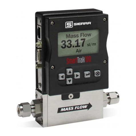
FCI ST100 series Mounting instructions

ST100 Series
Thermal Mass Flow Meter
Configuration Software
Manual
Fluid Components International LLC (FCI). All rights reserved.

ST100 Series Conguration Software
Fluid Components International LLC
Notice of Proprietary Rights
This document contains confidential technical data, including trade secrets and proprietary information which is the property of Fluid Components International LLC (FCI).
Disclosure of this data to you is expressly conditioned upon your assent that its use is limited to use within your company only (and does not include manufacture or
processing uses). Any other use is strictly prohibited without the prior written consent of FCI.
© Copyright 2015 by Fluid Components International LLC. All rights reserved. FCI is a registered trademark of Fluid Components International LLC. Information subject to change without notice.

ST100 Series Conguration Software 06EN003403 Rev. B
Fluid Components International LLC i
Table of Contents
List of Figures
Introduction.......................................................................................................................................................................................................................1
Installation........................................................................................................................................................................................................................1
Running the PC Configuration Application via USB ........................................................................................................................................................1
Basic Setup Tab Screens ..................................................................................................................................................................................................3
Advanced Setup Tab Screens...........................................................................................................................................................................................6
Configuration Tab Screens................................................................................................................................................................................................8
Diagnostics Tab Screens ................................................................................................................................................................................................10
Factory ............................................................................................................................................................................................................................12
FE1 Process Data............................................................................................................................................................................................................14
Parameter Reports..........................................................................................................................................................................................................15
Customer Service/Technical Support .............................................................................................................................................................................16
List of Tables
Figure 1 – Welcome Screen.............................................................................................................................................................................................1
Figure 2 – USB Connector on Customer Interface Board (Digital Interface Shown) .......................................................................................................1
Figure 3 – USB Connect Button, Welcome Screen..........................................................................................................................................................2
Figure 4 – Example Process Data Screen.........................................................................................................................................................................2
Figure 5 – Example Groups Tab Screen (Basic Setup) .....................................................................................................................................................3
Figure 6 – Example Units Screen .....................................................................................................................................................................................4
Figure 7 – Example Pipe Size Screen...............................................................................................................................................................................4
Figure 8 – Example Alarms Screen ..................................................................................................................................................................................4
Figure 9 – Example SD Card Logging Screen...................................................................................................................................................................5
Figure 10 – Example Totalizer Screen ..............................................................................................................................................................................5
Figure 11 – Example Pressure Offset Screen...................................................................................................................................................................5
Figure 12 – Example User Parameters Tab (Advanced Setup).........................................................................................................................................6
Figure 13 – Example Ethernet Tab (Advanced Setup) ......................................................................................................................................................7
Figure 14 – Example Data and Time Tab (Advanced Setup) ............................................................................................................................................7
Figure 15 – Example Download Calibration Tab (Advanced Setup).................................................................................................................................7
Figure 16 – Example Output Tab (Configuration)..............................................................................................................................................................8
Figure 17 – Example 4-20mA User Tab (Configuration) ...................................................................................................................................................9
Figure 18 – Example Modbus Tab (Configuration) ...........................................................................................................................................................9
Figure 19 – Example Extended Op. Mode Tab (Configuration).........................................................................................................................................9
Figure 20 – Example Group Switch Tab (Configuration).................................................................................................................................................10
Figure 21 – Example Status Screen (Diagnostics) .........................................................................................................................................................10
Figure 22 – Example Fault Log Tab (Diagnostics)...........................................................................................................................................................11
Figure 23 – Example Scheduled Tests Tab (Diagnostics)...............................................................................................................................................11
Figure 24 – Example Test Logs Tab (Diagnostics) ..........................................................................................................................................................11
Figure 25 – Example Factory Parameters Tab (Factory) .................................................................................................................................................12
Figure 26 – Example Identification Tab (Factory) ...........................................................................................................................................................12
Figure 27 – Example 4-20mA Factory Tab (Factory) .......................................................................................................................................................13
Figure 28 – Example Options Tab (Factory) ....................................................................................................................................................................13
Figure 29 – Example HART Tab (Factory) .......................................................................................................................................................................13
Figure 30 – Example Memory Tab (Factory) ...................................................................................................................................................................14
Figure 31 – Example Process Data Screen (FE1)............................................................................................................................................................14
Figure 32 – Example Parameter Report, Group 1...........................................................................................................................................................15
Figure 33 – Example Parameter Report, Group 5...........................................................................................................................................................15
Table 1 – Basic Setup Tabs ..............................................................................................................................................................................................3
Table 2 – Advanced Setup Tabs .......................................................................................................................................................................................6
Table 3 – Configuration Tabs............................................................................................................................................................................................8
Table 4 – Diagnostics Tabs.............................................................................................................................................................................................10
Table 5 – Factory Tabs....................................................................................................................................................................................................12

06EN003403 Rev. B ST100 Series Conguration Software
ii Fluid Components International LLC
INTENTIONALLY LEFT BLANK

ST100 Series Conguration Software
Fluid Components International LLC 1
Introduction
The ST100 Configuration software is a PC application that lets the user easily set up and configure the ST100 Series Thermal Mass Flow Meter
products. Use this tool for all instrument commissioning activity. This manual covers ST100 Configuration software v2.2.0.0.
Installation
Find the Software Configurator MSI install file in the Software folder on the product documentation CD. The file can be identified by name –
ST100
Configurator Setup.msi
. Copy this file to a location on your PC designated for ST100 documentation.
Run the MSI installer file and follow the on-screen instructions to complete the installation. The installation process places an application shortcut
icon on your PC desktop.
The ST100 Configurator icon looks like a pair of Binoculars.
Running the PC Conguration Application via USB
Double click the ST100 Configurator icon. The application opens to the Welcome Screen as shown below.
Connect the instrument to the PC using the USB cable provided then turn the power ON. The ST100 USB connector is located on the customer inter-
face board as shown in the figure below (remove blind lid for access).
Figure 1 – Welcome Screen
Figure 2 – USB Connector on Customer Interface Board (Digital Interface Shown)
ST100 Body
(Blind Lid
Removed)
Customer
Interface
Board
USB Connector
C01264-1-1

ST100 Series Conguration Software
2 Fluid Components International LLC
Click the USB connect button at the top of the Welcome Screen.
The ST100 Process Data screen shows the same data available on the instrument LCD display.
• Percent of range scale located on the top of the screen
• Flow
• Total Flow (if Mass or Volumetric units used)
• Temperature
• Pressure (for STP Series only)
• Calibration Group number and Group name
• Alarm and Fault indicators
The ST100 Series is set up using the configuration menu on the left side of the screen. The menu is displayed in a hierarchical tree structure:
Once connected, the ST100 Configuration application shows the Process Data screen as shown in the figure below.
Percent of Range
Configuration Menu
Flow
Temperature
Pressure
Group Number/Name
Alarm/Fault Indicators
C01261-1-1
Figure 4 – Example Process Data Screen
Figure 3 – USB Connect Button, Welcome Screen
USB Connect
Button
C01263-1-1

ST100 Series Conguration Software
Fluid Components International LLC 3
Basic Setup Tab Screens
Select the Basic Setup branch on the menu tree. The Groups Tab is the first of several tabs across the top of the screen. Each tab provides a
particular menu within the Basic Setup branch.
Figure 5 – Example Groups Tab Screen (Basic Setup)
The table below summarizes the tabs within the Basic Setup branch.
Table 1 – Basic Setup Tabs
Tab Name Tab Description Password Level
Groups Select and name groups. User
Units Select flow, temperature and pressure units. User
Pipe Size Select pipe type and dimensions. User
Alarms Select and set alarm requirements; select for logging. User
SD Card Logging Select logging requirements. User
Totalizer Select and reset Totalizer requirements. User
Pressure Offset Offset pressure transducer. User
[User password 2772]
To verify the current configuration of any setup parameter, click the Get from Device button on any of the Setup menus. After changing any of the
setup parameters, click the Send to Device button. Verify the parameter change by clicking the Get from Device button again. Observe that the
changed parameters are now displayed. The Basic Setup tab screens are shown below.
C01262-1-1
Tabs

ST100 Series Conguration Software
4 Fluid Components International LLC
Figure 6 – Example Units Screen
Figure 7 – Example Pipe Size Screen
Figure 8 – Example Alarms Screen

ST100 Series Conguration Software
Fluid Components International LLC 5
Figure 9 – Example SD Card Logging Screen
Figure 10 – Example Totalizer Screen
Figure 11 – Example Pressure Offset Screen

ST100 Series Conguration Software
6 Fluid Components International LLC
Advanced Setup Tab Screens
Select the Advanced Setup branch on the menu tree. The User Parameters Tab is the first of several tabs across the top of the screen. Each tab
provides a particular menu within the Advanced Setup branch.
The table below summarizes the tabs within the Advanced Setup branch.
Table 2 – Advanced Setup Tabs
Tab Name Tab Description Password Level
User Parameters Shows min/max process variable limits, K Factor, Density, Damping. User
Ethernet Sets Ethernet address values. User
Date and Time Set Clock date and time. User
Download Calibration
Lets users download a full calibration to their ST100 via a text file.
Contact FCI to obtain the .txt file that was generated by the factory
linearization software (Cal2).
User
[User password 2772]
To verify the current configuration of any setup parameter, click the Get from Device button on any of the Setup menus. After changing any of the
setup parameters, click the Send to Device button. Verify the parameter change by clicking the Get from Device button again. Observe that the
changed parameters are now displayed. The Advanced Setup Tab screens are shown below.
Figure 12 – Example User Parameters Tab (Advanced Setup)

ST100 Series Conguration Software
Fluid Components International LLC 7
Figure 13 – Example Ethernet Tab (Advanced Setup)
Figure 14 – Example Data and Time Tab (Advanced Setup)
Figure 15 – Example Download Calibration Tab (Advanced Setup)

ST100 Series Conguration Software
8 Fluid Components International LLC
Conguration Tab Screens
Select the Configuration branch on the menu tree. The Output Tab is the first of several tabs across the top of the screen. Each tab provides a
particular menu within the Configuration branch.
The table below summarizes the tabs within the Configuration branch.
Table 3 – Configuration Tabs
Tab Name Tab Description Password Level
Output Sets: 4-20 mA channels zero and span values, Freq and Pulse parameters. User
4-20mA User Manual mA Output loop check; configure/enable NAMUR fault. User
Modbus Sets Modbus communication parameters. User
Extended Op. Mode
Expands flow measurement capabilities by providing 4 additional modes
of operation. Refer to “Extended Operational Modes” in Complete Manual
06EN003400 for detailed information.
User
Group Switch Setup
Sets up automatic calibration group switching depending on specific pro-
cess data values or an external 4-20 mA output driving the ST100 auxiliary
input port. Refer to “Auto FE Calibration Group Switch (FCS)” and “Exter-
nal Control Group Switching (EGS)” in Complete Manual 06EN003400 for
detailed information.
User
[User password 2772]
To verify the current configuration of any setup parameter, click the Get from Device button on any of the Setup menus. After changing any of the
setup parameters, click the Send to Device button. Verify the parameter change by clicking the Get from Device button again. Observe that the
changed parameters are now displayed. The Configuration Tab screens are shown below.
Figure 16 – Example Output Tab (Configuration)

ST100 Series Conguration Software
Fluid Components International LLC 9
Figure 17 – Example 4-20mA User Tab (Configuration)
Figure 18 – Example Modbus Tab (Configuration)
Figure 19 – Example Extended Op. Mode Tab (Configuration)

ST100 Series Conguration Software
10 Fluid Components International LLC
Diagnostics Tab Screens
Select the Diagnostics branch on the menu tree. The Status Tab is the first of several tabs across the top of the screen. Each tab provides a par-
ticular menu within the Diagnostics branch.
Figure 20 – Example Group Switch Tab (Configuration)
The table below summarizes the tabs within the Diagnostics branch.
Table 4 – Diagnostics Tabs
Tab Name Tab Description Password Level
Status Indicates system status and fault flags. Read only
Fault Log Shows fault history. User
Scheduled Tests Enable/disable internal Delta R resistance check – results logged to SD card. User
Test Logs Shows internal Delta R resistor check (IDR) log results. User
[User password 2772]
Figure 21 – Example Status Screen (Diagnostics)

ST100 Series Conguration Software
Fluid Components International LLC 11
Figure 22 – Example Fault Log Tab (Diagnostics)
Figure 23 – Example Scheduled Tests Tab (Diagnostics)
Figure 24 – Example Test Logs Tab (Diagnostics)

ST100 Series Conguration Software
12 Fluid Components International LLC
Factory
Table 5 – Factory Tabs
Tab Name Tab Description Password Level
Factory Parameters For Factory use only. Factory
Identification For Factory use only. Factory
4-20mA Factory For Factory use only. Factory
Options For Factory use only. Factory
HART For Factory use only. Factory
Memory For Factory use only. Factory
Figure 25 – Example Factory Parameters Tab (Factory)
Figure 26 – Example Identification Tab (Factory)

ST100 Series Conguration Software
Fluid Components International LLC 13
Figure 27 – Example 4-20mA Factory Tab (Factory)
Figure 28 – Example Options Tab (Factory)
Figure 29 – Example HART Tab (Factory)

ST100 Series Conguration Software
14 Fluid Components International LLC
This screen displays the real time values of the following flow element parameters:
• RefR – Reference RTD resistance
• dR – Delta resistance between the active and reference RTDs
• TcdR – Temperature Compensated dR value
• Temperature – Real time temperature value
• Flow – Real time flow value
• Pressure – Real time pressure value (for STP models)
This screen can be helpful when diagnosing system faults.
FE1 Process Data
The FE1 description refers to Flow Element 1 of the system. The system is capable of supporting multiple flow elements but for the purpose of this
manual we will discuss a single point system with one flow element. Select the FE1 Process Data branch on the menu tree. The figure below
shows an example FE1 Process Data screen.
Figure 30 – Example Memory Tab (Factory)
Figure 31 – Example Process Data Screen (FE1)

ST100 Series Conguration Software
Fluid Components International LLC 15
Parameter Reports
A Parameter Reports screen displays the calibration information saved in the ST100 Series unit for a particular calibration group numbered 1-5.
Selecting a parameter report for a particular calibration group displays that group’s info/data. Similar to other setup menus there are Get and Send
buttons to receive (from ST100) and transmit (to ST100) a calibration parameter. Use of the Send button, however, is a factory-only operation that
requires a special password.
Figure 32 – Example Parameter Report, Group 1
Figure 33 – Example Parameter Report, Group 5

ST100 Series Conguration Software
16 Fluid Components International LLC
Customer Service/Technical Support
FCI provides full in-house technical support. Additional technical representation is also provided by FCI field representatives.
By Mail
Fluid Components International LLC
1755 La Costa Meadows Dr.
San Marcos, CA 92078-5115 USA
Attn: Customer Service Department
By Phone
Contact the area FCI regional representative. If a field representative is unable to be contacted or if a situation is unable to be resolved,
contact the FCI Customer Service Department toll free at 1 (800) 854-1993.
By Fax
To describe problems in a graphical or pictorial manner, send a fax including a phone or fax number to the regional representative. Again,
FCI is available by facsimile if all possibilities have been exhausted with the authorized factory representative. Our fax number is 1 (760)
736-6250; it is available 7 days a week, 24 hours a day.
By Email
FCI Customer Service can be contacted by email at: techsupport@fluidcomponents.com.
Describe the problem in detail making sure a telephone number and best time to be contacted is stated in the email.
International Support
For product information or product support outside the contiguous United States, Alaska, or Hawaii, contact your country’s FCI International
Representative or the one nearest to you.
After Hours Support
For product information visit FCI at www.fluidcomponents.com. For product support call 1 (800) 854-1993 and follow the prerecorded
instructions.
Point of Contact
The point of contact for service, or return of equipment to FCI is your authorized FCI sales/service office. To locate the office nearest you,
please go to www.fluidcomponents.com.
Other manuals for ST100 series
4
Table of contents
Other FCI Measuring Instrument manuals
FCI
FCI ST100A Series User manual

FCI
FCI ST100 series Mounting instructions
FCI
FCI PETROSENSE PHA-100Plus Setup guide

FCI
FCI MT86 Instruction manual
FCI
FCI ST51-1 Operating instructions

FCI
FCI ST100 series Owner's manual

FCI
FCI ST100 series User manual
FCI
FCI FLT93B Instruction manual
FCI
FCI ST50 Operating instructions

FCI
FCI MT100 User manual
