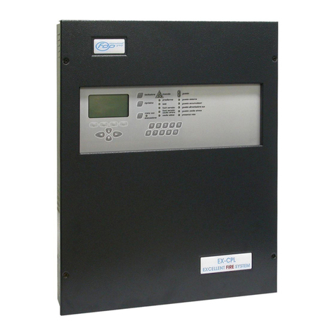
FDP CFN User guide

Page2of35
Rev. 1.03
INDEX
PART1PRELIMINARY REMARKSFORACORRECTWORKING..........................................4
1.1LINE CABLE TEST PROCEDURE BEFORE LOOP CONNECTION....................................4
1.1.1 Linecontinuity.................................................................................................................4
1.1.2 Isolation between+/-ofloop.........................................................................................4
PART2DETAILS................................................................................................................................5
PART3CONTROLPANELINSTALLATION.................................................................................6
3.1ABOUT SAFETY...................................................................................................................6
3.2HOWTO FIX THE CASE.......................................................................................................7
3.2.1 Metalcase.......................................................................................................................7
3.3CONNECTION......................................................................................................................8
3.3.1 Block powersupply.........................................................................................................9
3.3.2 Motherboard.................................................................................................................10
3.3.3 Connection tothepowersupply.....................................................................................11
3.4INSERTION AND REMOVING POINTS............................................................................11
3.5PANELDESCRIPTION.......................................................................................................11
3.5.1 Ledforsharedfunctions................................................................................................12
3.5.2 Ledofthezone..............................................................................................................12
3.5.3 Button descriptions........................................................................................................12
3.6MAINTENANCE.................................................................................................................13
3.6.1 Leds/buzzertest.............................................................................................................13
3.6.2 Dailycontrol.................................................................................................................13
3.6.3 Weeklycontrol...............................................................................................................13
3.6.4 Four-monthlycontrol....................................................................................................13
3.6.5 Yearlycontrol................................................................................................................14
PART4RAPIDPROCEDUREOFCONFIGURATIONCONTROLPANEL..............................15
4.1DEFAULT SETTING...........................................................................................................15
PART5ABOUTPROGRAMMING.................................................................................................16
5.1ACCESS LEVELS................................................................................................................16
5.1.1 Levelsfor finaluserand installer..................................................................................16
5.1.2 Level1...........................................................................................................................16
5.1.3 Level2...........................................................................................................................16
5.1.4 Level3...........................................................................................................................17
PART6ALARM–PREALARM-FAULT......................................................................................18
6.1ALARM................................................................................................................................18
6.2PRE-ALARM.......................................................................................................................18
6.3FAULT.................................................................................................................................19
6.3.1 Zonefault......................................................................................................................19
6.3.2 Outputfault...................................................................................................................19
6.3.3 Powerfault....................................................................................................................19
6.4SYSTEMFAULT.................................................................................................................19
6.5SILENCE (1ST LEVEL).........................................................................................................19
6.6SILENCE (2ND LEVEL)........................................................................................................20
6.7RESET..................................................................................................................................20
6.8DEFAULT SETTING RESTORATION................................................................................20
6.9PROGRAM SCHEMATICS.................................................................................................21

Page3of35
Rev. 1.03
PART7ZONEPROGRAMMING...................................................................................................22
7.1OUT OF SERVICE OF ZONE..............................................................................................22
7.2ZONE TEST.........................................................................................................................22
7.3ZONE PREALARM..............................................................................................................23
7.3.1 Automaticactivation<Out1>........................................................................................23
PART8SIRENOUTPUTPROGRAMMING..................................................................................25
8.1MANUAL ACTIVATION OUTPUT....................................................................................25
8.2SIREN OUTPUT SILENT....................................................................................................25
8.3OUTPUT DELAY.................................................................................................................25
PART9TECHNICALCHARACTERISTICS.................................................................................27
PART10 INSTALLERMENU..........................................................................................................29
10.1LEVEL1...............................................................................................................................29
10.2LEVEL2...............................................................................................................................29
10.3LEVEL3...............................................................................................................................29
PART11 POINTSDESCRIPTIONAND UTILIZATION..............................................................30
11.1DETECTOR.........................................................................................................................30
11.1.1 Smoke detector..............................................................................................................30
11.1.2 Heatdetector.................................................................................................................30
11.1.3 Multicriterion detector..................................................................................................30
11.1.4 Electricalschemes.........................................................................................................31
11.2CONVENTIONAL BUTTON...............................................................................................31
11.2.1 Glass break/Pushbutton..............................................................................................31
11.2.2 Glass breakbutton withled...........................................................................................31
11.2.3 Rearmablebutton withkey............................................................................................32
PART12 GENERICELECTRICALSCHEMES............................................................................33
12.1SIREN AND ELECTROMAGNET CONNECTION TO THE CONTROL PANEL...............33
12.2SOME CONNECTION POINTS...........................................................................................34
12.3OPEN COLLECTOR CONNECTION..................................................................................34
PART13 HOWTOSOLVETHEPROBLEMS...............................................................................35

Page4of35
Rev. 1.03
1.1LINECABLETESTPROCEDUREBEFORELOOPCONNECTION
1.1.1Linecontinuity
Check the resistorofline electroconductivecableswithtesterat200 Ωofresistorforline
electroconductivecablessuperiorto40 Ωistoo high!!
Possiblecausescan be:
-the line istoolong;
-looseclips;
-falsecontacts;
-cableofinsufficient section;
-partlycut off ordamaged cable.
The cablesmust usuallypresent aresistorbetween 10 and 15 Ω.
Besidesthe resistorofthe negativecableandthe positiveone must result similar.
1.1.2Isolationbetween+/ -ofloop
Withtesterat20KΩand the detectorsinsert, itmustmeasureaaboutvalue ofthe endofline
resistor.
PART 1
PRELIMINARYREMARKSFORACORRECT WORKING

Page5of35
Rev. 1.03
The fire-prevention CFN controlpanelwasdesigned inobservancetotherulesEN54-2and
EN54-4, and ithasthefollowing characteristics:
üThe availableversionsof thecontrolpanelareat 2–4–6zones.
üIt ispossibletoinstallonasinglezone upto20 activepoints(detectors,pointssupplied
fromzone line)pluspassivepoints(buttons,smokelinearbarrier,...)untiltoa
maximumof 32 totalpointsforzone.
The powersupplytothedeviceoccursthroughonly2cables.
Connectibledetectors:
Smokedetectors: RF1, SOD
Heat detectors: RT, TV
Multi-criteriadetectors: RFT1
Connectiblemodules:
Manualbuttons: P, P1, P5
Linearbarriersmokedetectors: RLF1
GAS detectors: GMR, GGR, GCR
Relayoutput modules: All devices witharelayoutput
•The detectorsmustbe plainwithalowpowersupplyof50µA,when the detectorisin
normallyfunctioning. If it goestoalarmmode,the currentis25mA.
•The controlpanelhavethe panelwithledsand buttonstoviewthe statussignaland to
programmerthe controlpanel.Faultsand alarmsarevisualizethrough the led luminous
and theyaresignalthrough the buzzeracousticof controlpanelthem.
•The controlpanelhas:
oasupervisedsiren outputforthe alarmsignalling (out1);
oasupervisedsiren outputforthe alarm/pre-alarmsignalling (out2);
oarelayoutput C-NO-NC forthe alarmsignalling(Relay1);
oarelayoutput C-NO-NC normallyon forthefault signalling (Relay2);
osixopen collectoroutputsof zone alarm.
•Allcontrolpanelprogramming must be made through the panelbuttons.
PART 2
DETAILS

Page6of35
Rev. 1.03
3.1ABOUTSAFETY
The controlpanelinstallation mustbe performedbyqualified staff. Onlyauthorized personnel
aredesignated toopenthe controlpanel;inside itispossibletofind somepartswithtension.
Productinstallationlocation.
Install theproductinadryplacetoprotectitfromatmosphericagents.Allowplentyofspace
around the producttoensureventilation.DoNotinstallthe productacrossornearanyheat
sourcesorindirtyplaceorexposing it tocorrosivesubstances.
Excessiveheatand/orheatingdevicescancompromisethe working and the productintegrity.
Ensureaproperventilationforthe product.
Humidityorpresenceofcondensation dropscan damage the product. Ifthereiscondensation,
makesuretowaitforthe producttodry.If theproducthasbeen conserved incoldplacefora
long time, itisnecessarylocateitinthe installationplaceand wait twohoursbeforeconnecting
it tothe 230Vacnetline.
WARNING:Onlyauthorized personnelaredesignated toopen the controlpanel.DONOTtry
torepairthe productorelsethe warrantyisnotvalid.Disconnectthe powermainand the
batteriesbeforeperforming themaintenanceon the product.
PART 3
CONTROL PANEL INSTALLATION

Page7of35
Rev. 1.03
3.2HOWTOFIXTHECASE
3.2.1Metalcase
The controlpanelweighsabout3.5Kgwithoutbatteriesinside.When fixing the caseata
surface,makesuretousesupportingelementsfittosupportthisweight. Incasereinforcethe
surfaceif necessary.
Precaution:onlyqualifiedstaffwhoiswellacquaintedwiththeprocedures describedin
thismanual.
Insertthe230Vac netlineinthecase,keepingfarawaythesameonefromtheprinted
circuitsandtherestofwiring.
Supplytothecontrolpanelthroughasuitablemagneto-thermicpowerswitch.Thenet
cablemusthaveminimumsectionof1.5mm andworkvoltageof250Vac.
ASSEMBLY(see picturefig. 1)
1.open thecontrolpanel;
2.removethe completepanelof motherboard;
3.punchoutthe pre-cut holesthat arenecessarytoinsertthe cables;
4.installthe caseinthe desired placeusingthe foursupportingholes;
5.replacethepanel.
fig.1

Page8of35
Rev. 1.03
3.3CONNECTION
The motherboardofthecontrolpanelinpicture2.The positionsoftheclipsand fusesare
pointed out.
+B
-B
~ ~ Batteryfuse
AUX24VFUSE CNCNO
Relay1 +-
24Vaux
.+-
Out1.+-
Out2.CNCNO
Relay2 +-
Line1
.+-
Line2.+-
3Line +-
4.Line +-
5.Line +-
6.Line 123456
Opencollector
Batteryfuse
Transformer
GND
Battery
24Vauxfuse Reay2
Relay1 24Vaux Output 1
Output 2 Zones Opencollector
Fig.2
Description of motherboardofthe controlpanel.

Page9of35
Rev. 1.03
3.3.1Blockpowersupply
+B
-B
~ ~ Battery fuse
Batteryfuse
Transformer
GND
Battery
N L
CASE
TRANSFORMER
+
-
+
-
12V7Ah 12V7Ah
DOOR
The block powersupplyiscomposed of:
1)Toroidaltransformer230Vac/ 33Vac.
2)Clipsforthe connectiontothe230Vac:
a.Neutral.
b.Line.
c.GND.
d.GND of the case.
e.Protection fusefromthe 230Vac.
3)Twobatteriespadof 12V7Ah.
4)Clipsforthe motherboardpowersupply:
a.(-B, +B)batterypad.
b.GND.
c.(~~)transformer.
d.Protection fusefromthe batteryconnection.
WARNING:afterthe cableconnectionofthe powersupplytothe GND-N-LclipsofAC-DC
Adaptor,itisimportanttoimmobilizethe three electricalcableswithaplasticstrip.Itis
necessarytoprevent that electricalcablesarefree tomove.
WARNING:the powersupplycablemusthavethe ground electricalcable(GND)morelong
respect theline (L)andneuter(N)cables.

Page10 of35
Rev. 1.03
3.3.2Motherboard
AUX24VFUSE CNCNO
Relay1 +-
24Vaux
.+-
Out1.+-
Out2.CNCNO
Relay2 +-
Line1.+-
2.Line +-
3.Line +-
4.Line +-
5.Line +-
6.Line 123456
Opencollector
24Vauxfuse Relay1
Relay2
24Vaux Output 2
Output 1 Zones Opencollector
Endof lineresistors: 10Kohm1/4W 3.9Kohm½W
The motherboardiscomposed of:
1)One fuseforthe24Vdcauxoutputprotection.
2)Tworelayoutputs(N-NC-NO):
a.Relay1forthe alarmsignalling.
b.Relay2normallyon forthefault signalling.
3)Twosupervised sirenoutputs:
a.Output 1forthealarmsignalling.
b.Output 2forthepre-alarm/alarmsignalling.
4)Two,fourorsixsupervisedzone inputs(variablenumberatdepending ontype ofthe
controlpanel).
5)Outputsofzonerepeat; two,fourorsixopen collectoroutputs(variablenumberat
dependingon typeof thecontrolpanel).

Page11 of35
Rev. 1.03
3.3.3Connectiontothepowersupply
Executethe connectionswithsuitablematerialsand proceduresprescribedbythe rulesin
force.Donotexecutethe connection tothe netwithoutfirstdisconnecting the external
magneto-thermic.
NOTE
•Atthe timeofinstallation always connectfirstthe net230Vacand then the batteries.In
that waydangeroussparks areavoided.
•The netinputcabletothe controlpanelmustbe connected toasuitablemagneto-
thermicpowerswitchtomakeeasierthemaintenance.The minimumsection ofnet
cablemust be of 1.5mm.
•All thecablesconnected tothe controlpanelmustbe fireproof. The cableofearth,the
net ground must be connectedtotheearthclipof netinput.
3.4INSERTIONAND REMOVING POINTS
Tomodify/insert/removepointsofazone,itisnecessarytoputitinoutofserviceandto
disconnect thecablesfromthe controlpanelclips.
The usermustnotinstall otherbypass orexpansion whichdo notbelong tosameproduction
range, becausethe controlof the cablestatusisonlyguaranteed at the line that hasthe endof
line resistor.
Forthe pointconnectionstothezone (detector,button,etc…),the usermustreferenceatthe
chapter PART9.
3.5PANELDESCRIPTION
ZONES
ZONE ALARMS
FAULT
-
DIS
ABLE/TEST
ZONE BUTTONS
ACCESS LEVEL
SIREN
OUT OF SERVICE
SILENT MODE
RESET
TEST
POWER SUPPLY
ALARM
PREALARM
FAULT
POWER FAULT
SYSTEM FAULT

Page12 of35
Rev. 1.03
3.5.1Ledforsharedfunctions
Listedbelowtherearethe description ofthe corresponding mainleds:
LED Colour Description
POWERSUPPLY Green
Normally on,it indicatesif the control panelissupplied.
Slow flashing it indicatesif the 230Vacpowerismissing.Afterabout20
minutesfromthe 230Vacismissing,the control panelgoesto fault.
Off whenthe control panelisnot supplied.
ALARM Red Normally off.
Slow flashing it indicatesthe alarm status.
Fixed lightit indicatesthatthe alarm issilenced.
PREALARM Red Normally off.
Slow flashing it indicatesthe pre-alarm status.
Fixed lightit indicatesthatthe pre-alarm issilenced.
FAULT Yellow Normally off.
Slow flashing it indicatesthe fault status.
Fixed lightit indicatesthatthe fault relay outputisplaced to outof service.
POWERFAULT Yellow Normally off.
Slow flashing it indicatesthatthe 230Vacismissing.
Fixed lightit indicatesthe battery fault.
SYSTEM FAULT Yellow Normally off.
Fixed lightit indicatesthe control panelfault.
TEST Yellow Normally off.
Fastflashing whenthe control panelisinthe zone teststatus.
OUTOF SERVICE Yellow Normally off.
Fixed lightwhenatlastazone oraoutput(sirenorrelay)isinoutof service.
SIREN Yellow
Normally off.
Slow flashing it indicatesthe fault statusof the sirenoutput(opencircuit or
shortcircuit).
Fastflashing it indicatesthatasirenoutputisactive.
Fixed lightit indicatesthatthe alarm/pre-alarmoutputsareinoutof service.
LEVEL Yellow
Normally off.
Fixed lightit indicatesthatthe level2isactive.
Slow flashing it indicatesthatthe level3isactive.
Fastflashing it indicatesthatthe levelaccessisactive.
3.5.2Ledofthezone
Listedbelowtherearethe description ofthe corresponding ledsforthe zones:
LED Colour Description
ZONEALARM Red
Normally off.
Fixed lightit indicatesthe alarm/pre-alarm of the zone.
Fastflashing it indicatesthe alarmstatusof the zone causesfromamanual
alarm.
FAULT –OOS/TEST Yellow
Normally off.
Fixed lightit indicatesthatthe zone isto outof service.
Slow flashing it indicatesthe fault statusof the zone.
Fastflashing it indicatesthe teststatusof the zone.
3.5.3Buttondescriptions
Listedbelowtherearethe description ofthe corresponding button commands:
Button Description
SILENT Level1: it permitsthe silentof the internalbuzzer.
Level2: it permitsthe silentof the internalbuzzerand sirenand relay outputs.
RESET Level2: it permitsthe resetof the alarmsand faultssignalling (led,relay and siren
outputs).
Level3: it permitsthe resetof the alarmsand faultssignalling,and the default setting

Page13 of35
Rev. 1.03
restorationof the control panel.
TEST Level2: it lightsall ledsand internalbuzzerforatime of 5s.
Level3: it permitsto putazone intestmode.
OUTOF SERVICE Level2: it permitsto setthe zone and the siren/relay outputsto outof service.
Level3: it permitsto setthe zone asalarmorpre-alarm mode.
SIREN Level2: it permitsto active the sirenoutputs.
Level2, onalarm status,it permitsto putthe delaysto zeroof sirenoutput.
Level3: it permitsto setthe sirenoutputdelays.
LEVEL
Itpermitsto access to 2and 3levels.
Itpermitsto escape frommenuswithoutmodification.
Level2: it permitsto change the password of 2level.
Level3: it permitsto change the password of 3level.
3.6MAINTENANCE
The maintenancemeasuresadvised inEN54-14 must be followed.
3.6.1Leds/buzzertest
It ispossibletoexecutethe ledsand buzzertest fromthe controlpanel.
Procedure:
•Access at level2.
•Push<TEST>button.
Thisfunctionlightsupallledsandit activestheinternalbuzzerand fault relayforatimeof 5s.
3.6.2Dailycontrol
The userwillcheck that:
üThe controlpanelworks properly.Otherwisethe faultswillbe reported and registered
and the maintenancestaff must be informed.
üIt isadvisablethat alloranyfaultsduring testing ornoted previously, aresolved assoon
aspossible, foracorrectfunctioning of the controlpanel.
3.6.3Weeklycontrol
üIt isadvisabletocheck thestatusof disconnected and connectedbatteries.
üAdetectororabutton willbe started up totestthe controlpaneland theconnected
fittingsof alarm. It issuitabletocheck adifferent zone everymonth.
üWhereitisadmitted,informthe firebrigade orthe controlcentre.
Anymalfunctioning mustbe noted inthe eventregister.The problemsmustbe solved assoon
aspossible,incasecontacting theinstaller.
3.6.4Four-monthlycontrol
The maintenancestaff must carryout the following controls:
üLookoverthe notesofthe event register.
üExamine allthe connectionsof batteries.
üCheck the alarmfunctioning,auxiliaryfault of the controldeviceand signaller.

Page14 of35
Rev. 1.03
üVisualinspectionofthe controldevicesandsignaller,apossibleriseinhumidityorany
othertypeof decay.
üCheck therearenotstructuralchangesthatcan causethemalfunctioningofthe
detectors,manualbuttonsorsirens. Inthiscasecarryout avisualinspection, too.
Anyproblemmustbe notedintheeventregister,solvingtheprobableproblemsassoonas
possible.
3.6.5Yearlycontrol
The maintenancestaff must havethedutytoperformthe following controls:
üCarryoutthe controlproceduresadvised daily, monthlyand four-monthly.
üTestthe controlpanelandcheckallthe detectorsworkasrecommended bythe
manufacturer(check the parameters).
üLookovervisuallyallthe connectionstothe devicesandrelativesupportsaresafe, they
arenotdamaged and areprotected properly.
üExamine and check allthebatteries.
Anyfaultmust be noted intheeventregister,solving the problemsassoon aspossible.

Page15 of35
Rev. 1.03
WARNING:IMPORTANTNOTES FORTHESTARTUPOFTHECONTROLPANEL
All the zonesand siren outputsmusthavetoconnectthe end ofline resistors(foryourvalues
tosee PART9).Atfirstactivation ofthecontrolpanel,toconnectthe powersupplyand after
the batteries.
Toverifythat thestart test hasnot faults.
4.1DEFAULT SETTING
At firsttimethe controlpanelhasthefollowingsetting:
1)allzonesareinservice(no out ofservice);
2)allzonesareinalarmmode (singleconsent)and the “Automaticactivation”propertyof
the <Out1>outputisdisabled (see chapter 7.3.1);
3)the siren outputdelayissetup onzeroseconds(0s).
The controlpanelprogramming remainsinthe memory,alsoifthe controlpanelisoff. Ifthe
userwantstorestorethe defaultparameters,itisnecessarytodo a2nd levelreset(see the
chapter 6.8).
PART 4
RAPIDPROCEDUREOF CONFIGURATIONCONTROL
PANEL

Page16 of35
Rev. 1.03
5.1ACCESS LEVELS
5.1.1Levelsforfinal userandinstaller
The controlpanelishasbeen planned following the EN54-2norms.Thisrulegivesatleast
three different access level.
The access levelsaredivided asdescribed below.
The controlpanelisnormalitystatusatlevel1.Toaccess tosuperiorlevels,itisnecessaryto
insert the appropriated codes.
N.B.:thecodeoflevel3mustbeusedonlybythequalifiedtechniciantothe
programmingofthecontrol panel.
5.1.2Level1
Levelforthe finaluser.It permitstocheck the controlpanelstatusand todo the silencemode
of the internalbuzzer.
5.1.3Level2
Access allowed tothe systemmanagement. All signalsand commandsof the controlpanelare
available.Inthislevelitispossibletoenabledordisabled thezones,toactivatetheoutputs,to
test the ledsand the internalbuzzer, torestorealarmsorfaultsand tosilenceoutputs.
Procedure:
•Push<LEVEL>button (the led flashesfast).
•Insert thepasswordoflevel2(default 222).
The led <LEVEL>isonat fixed light.
Toabort theprocedure, push<LEVEL>button.
Proceduretomodifythe passwordoflevel2:
•Push<LEVEL>button (the led flashesfast).
•Insert thepasswordoflevel2.
•Push<LEVEL>button within2seconds(theleds<TEST>,<OUT OF SERVICE>and
<SIREN>flashfast).
•Insert thenewpasswordoflevel2.
•Reinsert the newpasswordof level2(adoublebeep givesthe passwordchange; along
beep givesachangeerror).
It isnot possibletohavethe passwordoflevel3equaltolevel2.
Toabort theprocedure, push<LEVEL>button.
PART 5
ABOUT PROGRAMMING

Page17 of35
Rev. 1.03
5.1.4Level3
Access allowed onlytothe installer.Allfunctionsareaccessibleinthisleveland itispossible
whichevermodificationtochange everysetting:torestorethe defaultconfiguration,tostart the
test function, tosetalarmorpre-alarmof the zonesand todelaythe sirenoutputs.
Procedure:
•Push<LEVEL>button (the led flashesfast).
•Insert thepasswordoflevel3(default 333).
The led <LEVEL>isonand itflashesslow.
Toabort theprocedure, push<LEVEL>button.
Proceduretomodifythe passwordoflevel3:
•Push<LEVEL>button (the led flashesfast).
•Insert thepasswordoflevel3.
•Push<LEVEL>button within2seconds(theleds<TEST>,<OUT OF SERVICE>and
<SIREN>flashfast).
•Insert thenewpasswordoflevel3.
•Reinsert the newpasswordof level3(adoublebeep givesthe passwordchange; along
beep givesachangeerror).
It isnot possibletohavethe passwordoflevel2equaltolevel2.
Toabort theprocedure, push<LEVEL>button.

Page18 of35
Rev. 1.03
When the controlpanelworks innormalmode,itisinzonesand siren outputscontrolstatus.
The controlpanelchangesstatusonlywhen therearethesecases:
1.Alarm
2.Pre-alarm
3.Fault
4.Systemfault
6.1ALARM
Whenthe controlpanelfindsaalarm, it gives:
üled <ALARM>on, slowflashing;
üled<ALARM ZONE>on,continuousifone ortwodetectorshavegone intoalarm;on
withquickintermittentflashesif amanualalarm hasbeen triggered;
üinternalbuzzerisactiveand led <SILENCE>on, slowflashing;
üthe outputs<Out1>and <Out2>areactivatedafterthe presetdelaytimehaselapsed;
atthe activation ofoneofthe twooutputs,the led <SIREN>flashesquicklywhenever
one ofthe twosiren outputsisactivated.Thedelays areresetto0value ifand when:
anotherdetectorofthe zoneinalarmisactivated,orifamanualalarmistriggered.
When severaldetectorsareinalarmsimultaneouslyon differentzones,thedelaywill
not be automaticallyreset;
üthe Open Collectoroutputof the alarmed zone isactivated;
üoutput <Relay1>active.
Incaseof silencemode the leds<ALARM>and<SILENCE>remainalways on.
6.2PRE-ALARM
Incaseapre-alarmmode isengaged(justwithone detectorinalarmand one zonepresetfor
the pre-alarmmode), the controlpanelrevealsthe following signals:
üled < PRE-ALARM>on, slowflashing;
üled <ALARM ZONE>on, continuous;
üinternalbuzzerisactiveand led <SILENCE>on, slowflashing;
üthe output<Out2>isactivated afterhaving waited the presetdelay;the activation of
bothoutputs,theled <SIREN>hasquickintermittentflashing signaltoconfirmthe
<Out2> ison.The delays areresetto0value ifand when:anotherdetectorofthe
zone inalarmisactivated,orifamanualalarm istriggered.When severaldetectorsare
inalarmsimultaneouslyon different zones,thedelaywillnot beautomaticallyreset;
üthe output<Out1>remainsoff and itactivatesif“Automaticactivation”setting is
enabled (see chapter 7.3);
üthe Open Collectoroutputof the alarmed zone isactivated.
Incaseof silencemode the leds<PRE-ALARM>and <SILENCE>remainalways on.
If the ControlPanelrevealsanotheralarmactivity,itswitchesfromthe pre-alarmstateto
Alarm.
PART 6
ALARM–PREALARM-FAULT

Page19 of35
Rev. 1.03
6.3FAULT
Whenthe controlpanelfindsafault:
üled < FAULT>on, slowflashing;
üintermittent buzzeractive;
üthe output switchesto<Relay2>;
üthe powersourceled turnson.
Thisfault statusremainsuntilthe faultsarerestored.
6.3.1Zonefault
If azone goestofault (short circuitoropen circuit)the led zone relativetothe zonewillturnon
and giveaslowflashintermittence.Asthe faulton the zone isrestored,the controlpanelis
restoredtoo.
6.3.2Outputfault
If asiren outputgoestofault(shortcircuitoropen circuit)The<SIREN>led ison withaslow
flashintermittence.Asthe faultof theoutputisrestored, thecontrolpanelisrestored too.
6.3.3Powerfault
Therearetwotypesof powerfaults:
230Vac fault
If the 230Vacismissing formore5minutes,the powerfaultsignallingisgiven,the <POWER
FAULT>ledbeginstoflashwithaslowflashintermittenceand the controlpanelgoestofault
status.
If the faultisrestored,the controlpanelisrestored too.
Batteryfault
If thebatteryismissing/foultformore5minutes,thepowerfaultsignalling isgiven,the
<POWER FAULT>led isonand the controlpanelgoestofault status.
If the faultisrestored,the controlpanelisrestored too.
6.4SYSTEMFAULT
Thisfaulttypehassourcefromabad functioningofthemicro-controller.Thisfaultisnot
resolved fromfinaluser, butitisnecessarytocontact thesysteminstaller.
Toresolvethisproblemitispossibletoputoffthe controlpanel(totakeoff powersupplyand
battery).Towaitmoreor10s(+/-) and then connectagainthe batteryand powersupply.If the
fault persists;contactthe manufacturer.
During thisprocedure, the <Relay2>faultrelayand internalbuzzerwillbe activated.
6.5SILENCE(1st LEVEL)
Firstlevelsilencepermitsonlytosilent theinternalbuzzer.
Procedure:
•Push<SILENCE>button.

Page20 of35
Rev. 1.03
The <SILENCE>led isonuntil:
1)anewstatuschangeof thecontrolpanelthatrequiresthe buzzeractivations;
2)thereisanautomaticreset ofthe fault whichhasgenerated the buzzeractivation;
3)the resetprocedureislaunched.
6.6SILENCE(2nd LEVEL)
Second levelsilencepermitstosilentthe internalbuzzerand torestorethesiren relayoutputs.
Procedure:
•Access at level2.
•Push<SILENCE>button.
The <SILENCE>led isonuntil:
1)anewstatuschangeof thecontrolpanelthatit requiresthe buzzeractivations;
2)thereisanautomaticreset ofthe fault whichhasgenerated the buzzeractivation;
3)the resetprocedureislaunched.
6.7RESET
The controlpanelreset permitstorestorethenormalstatusofthe controlpanel.
The reset command does:
1)restoration of the sirenand relayoutputs;
2)silent mode of the internalbuzzer;
3)restoration ofallzones(duringthe reset, allzone outputsareset to0V);
4)restoration ofallfault andalarmsignals.
Procedure:
•Access at level2.
•Push<RESET>button.
The resetemploys approximately10s;duringthisprocedure,allledsareon.The opearation
terminateswiththesound of adouble“beep”.
6.8DEFAULT SETTING RESTORATION
Thisprocedurehassamefunctionsofreset(chapter 6.7)andbesidesitpermitstosetthe
controlpanelwithfactorydefault values(seechapter 4.1).
Procedure:
•Access at level3.
•Push<RESET>button.
The resetemploys approximately10s;duringthisprocedure,allledsareon(withthe exception
of the onethatindicatesthe systemfault).
Table of contents
Other FDP Control Panel manuals
Popular Control Panel manuals by other brands
Nakanishi
Nakanishi E4000-PB Operation manual
Radionics
Radionics D10024A user manual
DMP Electronics
DMP Electronics XR550 series installation guide
Bentel Security
Bentel Security K-NET installation manual
BLUGUARD
BLUGUARD SmartBus P900-TI6N user manual
Pentair
Pentair Hydromatic H-03-000 Installation and service manual

