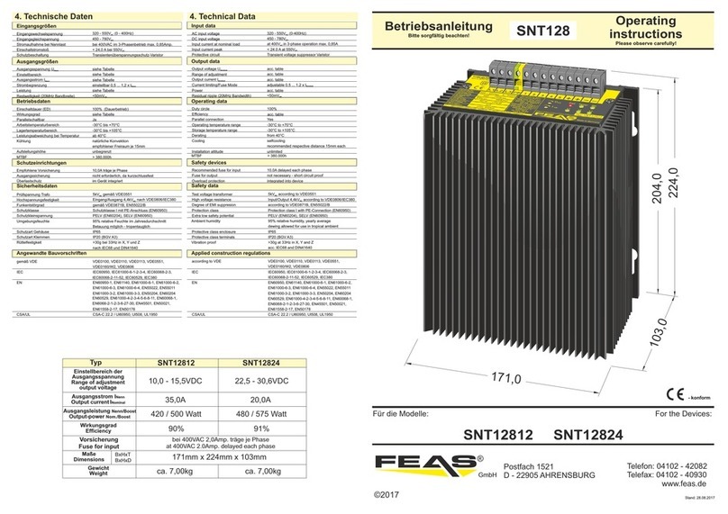
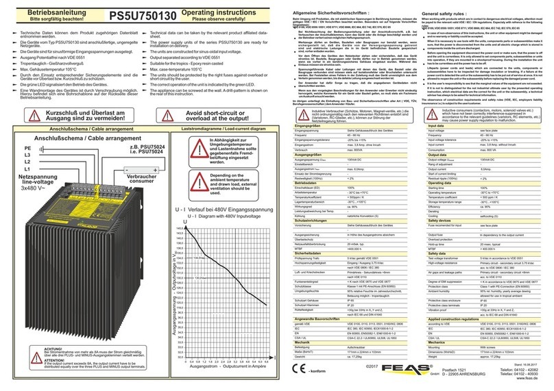
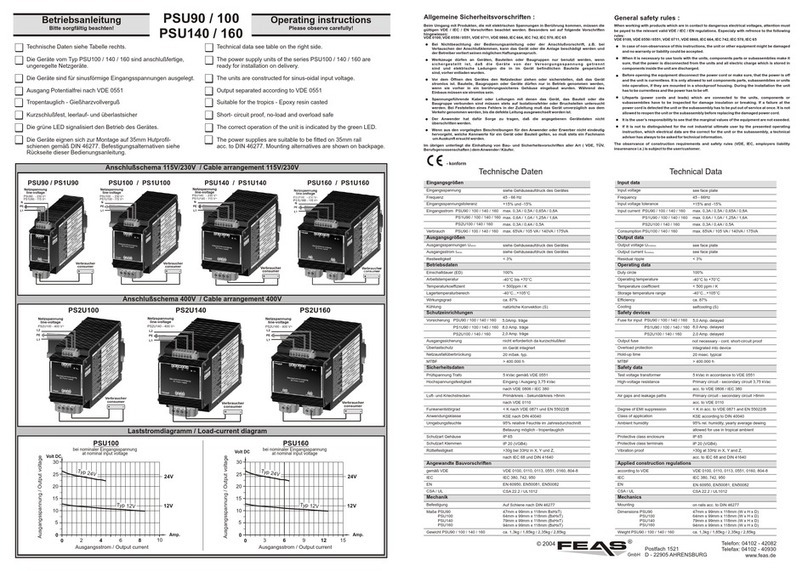
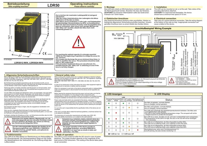
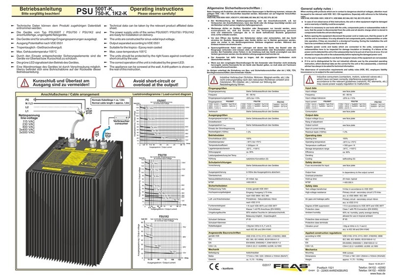
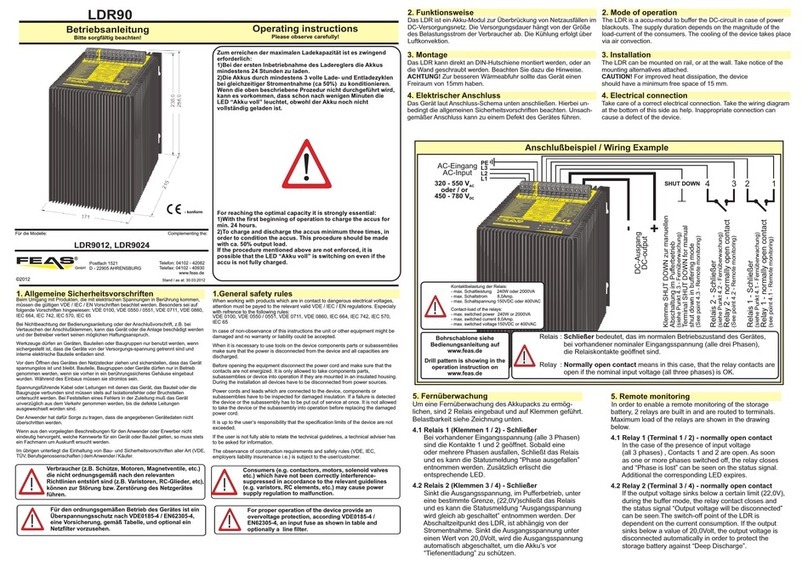
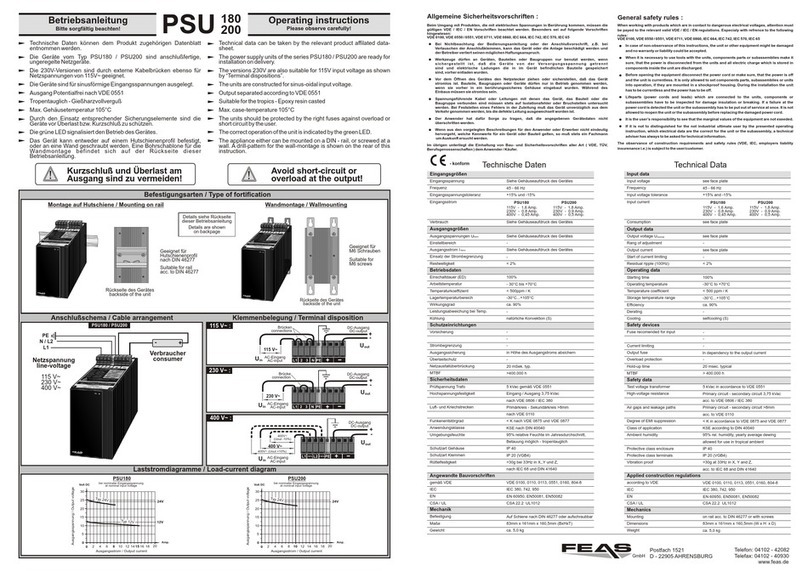
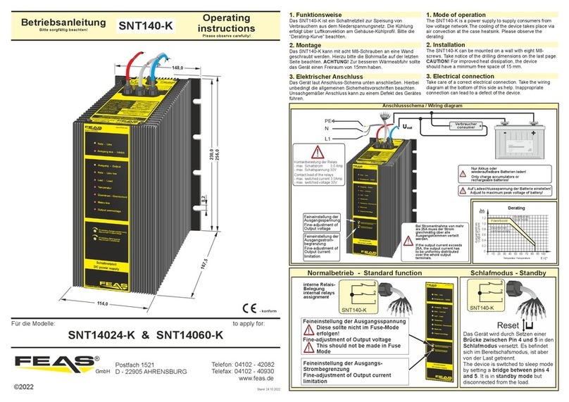
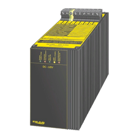
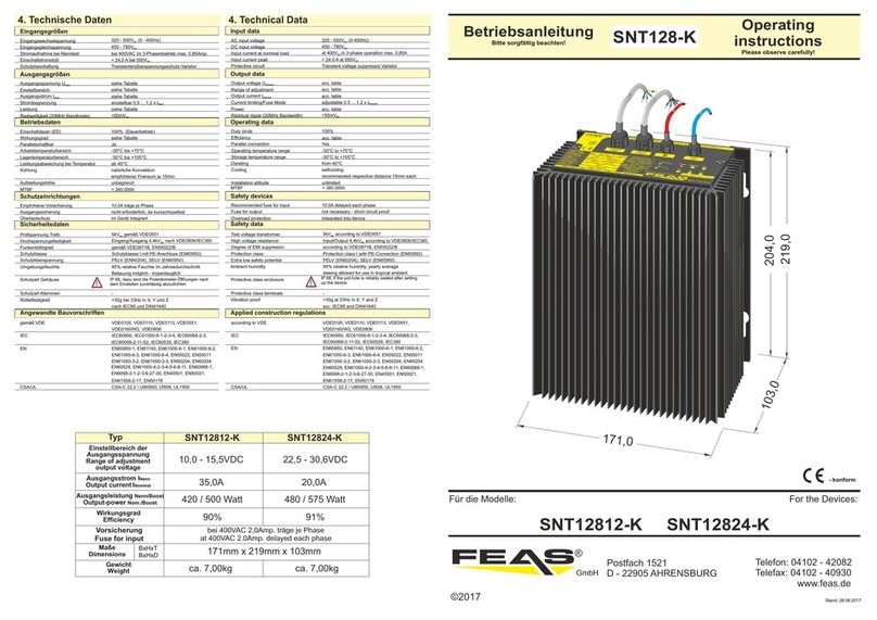
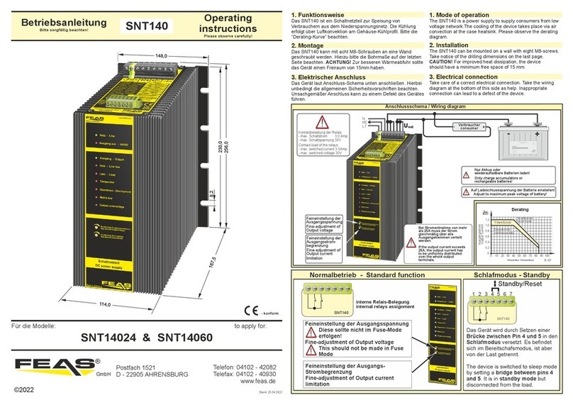
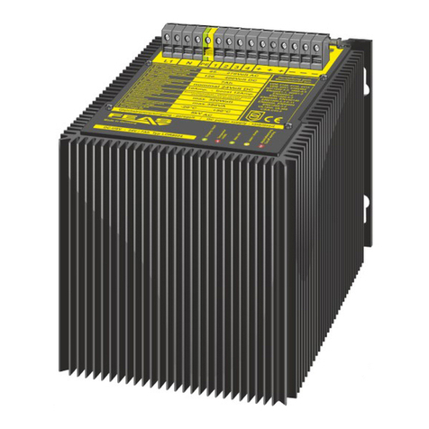
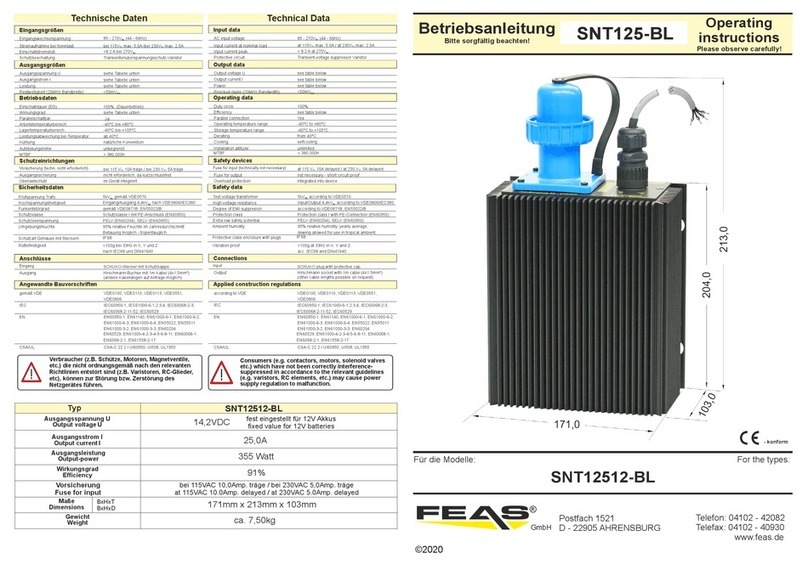
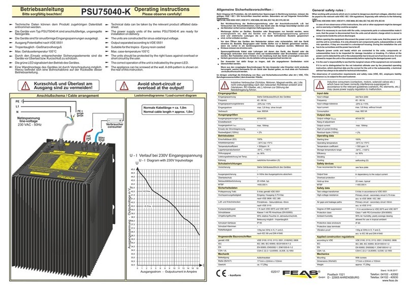
FEAS LDR8024-RS User manual

Stand / as at: 23.11.2017
© 2011
Postfach 1521
D - 22905 Ahrensburg
Telefon: +49 4102 42082
Fax: +49 4102 40930
E-Mail: [email protected]
Internet: www.feas.de
Betriebsanleitung
Bitte sorgfältig beachten!
Operating instructions
Please observe carefully!
LDR8024-RS Bitte sorgfältig beachten! Please observe carefully!
- konform
- LDR8024-RS -
Für die Modelle: Complementing the:
GmbH
Postfach 1521
D - 22905 AHRENSBURG
Telefon: 04102 - 42082
Telefax: 04102 - 40930
www.feas.de
©2011
®
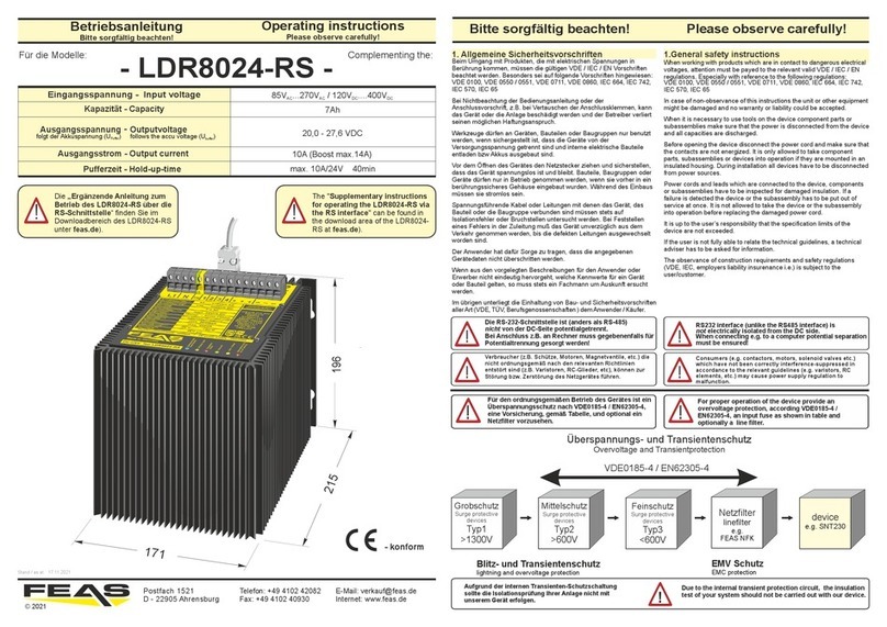
Verbraucher (z.B. Schütze, Motoren, Magnetventile, etc.) die
nicht ordnungsgemäß nach den relevanten Richtlinien
entstört sind (z.B. Varistoren, RC-Glieder, etc), können zur
Störung bzw. Zerstörung des Netzgerätes führen.
Die RS-232-Schnittstelle ist (anders als RS-485)
nicht von der DC-Seite potentialgetrennt.
Bei Anschluss z.B. an Rechner muss für Potential-
trennung gesorgt werden!
Consumers (e.g. contactors, motors, solenoid valves etc.)
which have not been correctly interference-suppressed in
accordance to the relevant guidelines (e.g. varistors, RC
elements, etc.) may cause power supply regulation to
malfunction.
RS232 interface (unlike the RS485 interface) is
not electrically isolated from the DC side.
When connecting e.g. to a computer potential separation
must be ensured!
Für den ordnungsgemäßen Betrieb des Gerätes ist ein
Überspannungsschutz nach VDE0185-4 / EN62305-4,
eine Vorsicherung, gemäß Tabelle, und optional ein
Netzfilter vorzusehen.
For proper operation of the device provide an
overvoltage protection, according VDE0185-4 /
EN62305-4, an input fuse as shown in table and
optionally a line filter.
1. Allgemeine Sicherheitsvorschriften
Beim Umgang mit Produkten, die mit elektrischen Spannungen in Berührung kommen,
müssen die gültigen VDE / IEC / EN Vorschriften beachtet werden. Besonders sei auf
folgende Vorschriften hingewiesen: VDE 0100, VDE 0550 / 0551, VDE 0711, VDE
0860, IEC 664, IEC 742, IEC 570, IEC 65
Bei Nichtbeachtung der Bedienungsanleitung oder der Anschlussvorschrift, z.B. bei
Vertauschen der Anschlussklemmen, kann das Gerät oder die Anlage beschädigt
werden und der Betreiber verliert seinen möglichen Haftungsanspruch.
Werkzeuge dürfen an Geräten, Bauteilen oder Baugruppen nur benutzt werden, wenn
sichergestellt ist, dass die Geräte von der Versorgungsspannung getrennt sind und
interne elektrische Bauteile entladen bzw Akkus ausgebaut sind.
Vor dem Öffnen des Gerätes den Netzstecker ziehen und sicherstellen, dass das Gerät
spannungslos ist und bleibt. Bauteile, Baugruppen oder Geräte dürfen nur in Betrieb
genommen werden, wenn sie vorher in ein berührungssicheres Gehäuse eingebaut
wurden. Während des Einbaus müssen sie stromlos sein.
Spannungsführende Kabel oder Leitungen mit denen das Gerät, das Bauteil oder die
Baugruppe verbunden sind müssen stets auf Isolationsfehler oder Bruchstellen
untersucht werden. Bei Feststellen eines Fehlers in der Zuleitung muß das Gerät
unverzüglich aus dem Verkehr genommen werden, bis die defekten Leitungen
ausgewechselt worden sind.
Der Anwender hat dafür Sorge zu tragen, dass die angegebenen Gerätedaten nicht
überschritten werden.
Wenn aus den vorgelegten Beschreibungen für den Anwender oder Erwerber nicht
eindeutig hervorgeht, welche Kennwerte für ein Gerät oder Bauteil gelten, so muss
stets ein Fachmann um Auskunft ersucht werden.
Im übrigen unterliegt die Einhaltung von Bau- und Sicherheitsvorschriften aller Art (VDE,
TÜV, Berufsgenossenschaften ) dem Anwender / Käufer.
1.General safety instructions
When working with products which are in contact to dangerous electrical voltages,
attention must be payed to the relevant valid VDE / IEC / EN regulations. Especially
with reference to the following regulations:
VDE 0100, VDE 0550 / 0551, VDE 0711, VDE 0860, IEC 664, IEC 742, IEC 570,
IEC 65
In case of non-observance of this instructions the unit or other equipment might be
damaged and no warranty or liability could be accepted.
When it is necessary to use tools on the device component parts or subassemblies
make sure that the power is disconnected from the device and all capacities are
discharged.
Before opening the device disconnect the power cord and make sure that the
contacts are not energized. It is only allowed to take component parts,
subassemblies or devices into operation if they are mounted in an insulated housing.
During installation all devices have to be disconnected from power sources.
Power cords and leads which are connected to the device, components or
subassemblies have to be inspected for damaged insulation. If a failure is detected
the device or the subassembly has to be put out of service at once. It is not allowed
to take the device or the subassembly into operation before replacing the damaged
power cord.
It is up to the user’s responsibility that the specification limits of the device are not
exceeded.
If the user is not fully able to relate the technical guidelines, a technical adviser has
to be asked for information.
The observance of construction requirements and safety regulations (VDE, IEC,
employers liability insurenance i.e.) is subject to the user/customer.
!
Zum Erreichen der maximalen Ladekapazität bitte
beachten:
1) Bei der ersten Inbetriebnahme des Ladereglers
die Akkus mindestens 24 Stunden laden!
2) Die Akkus durch mindestens 3 volle Lade- und
Entladezyklen bei gleichzeitiger Stromentnahme
(ca. 60%) konditionieren!
Ansonsten kann es vorkommen, dass schon nach wenigen
Minuten die LED “Akku voll” leuchtet, obwohl der Akku
noch nicht vollständig geladen ist.
For reaching the maximum capacity it is strongly
recommended:
1) Charge the batteries for at least 24 hours
when using the charge controller for the very first time!
2) Condition the batteries by at least 3 full charge and
discharge cycles with simultaneous current drain
(approx. 60%)!
Otherwise, the "Akku voll" LED may light up after just a
few minutes, even though the battery is not yet fully
charged.
171
196
215

2. Funktionsweise
Das LDR ist ein Akku-Modul zur Überbrückung von Netzausfällen
im DC-Versorgungsnetz. Die Versorgungsdauer hängt von der
Größe des Belastungsstroms der Verbraucher ab. Die Kühlung
erfolgt über Luftkonvektion.
3. Montage
Das LDR kann direkt an die Wand oder ein Montageblech
geschraubt werden. Beachten Sie dazu die Hinweise.
ACHTUNG! Zur besseren Wärmeabfuhr sollte das Gerät einen
Freiraum von min. 15mm haben.
3. Installation
The LDR can be mounted at the wall or any mounting sheet. Take
notice of the mounting alternatives attached.
CAUTION! For improved heat dissipation, the device
should have a minimum free space of 15mm.
4. Elektrischer Anschluss
Das Gerät laut Anschluss-Schema unten anschließen. Hierbei un-
bedingt die allgemeinen Sicherheitsvorschriften beachten. Unsach-
gemäßer Anschluss kann zu einem Defekt des Gerätes führen.
4. Electrical connection
Take care of a correct electrical connection. Take the wiring
diagram at the bottom of this side as help. Inappropriate connection
can cause a defect of the device.
2. Mode of operation
The LDR is a buffer-modul to buffer the DC-circuit in case of power
blackouts. The supply duration depends on the magnitude of the
load-current of the consumers. The cooling of the device takes
place via air convection.
5. RS-232/RS-485 interface
The unit can be connected to a computer via the D-Sub-9 socket
of the LDR80-RS. RS-232 or RS-485 data can be exchanged. The
decisive factor here is the pin assignment of the interface cable
used (see tables on the right).
5. RS-232/RS-485-Anschluss
Das Gerät kann über die D-Sub-9 Buchse des LDR80-RS an
einen Computer angeschlossen werden. Dabei können RS-232-
oder RS-485-Daten ausgetauscht werden. Entscheidend ist
dabei die Steckerbelegung des verwendeten Schnittstellen-
kabels gemäß nebenstehender Tabellen.
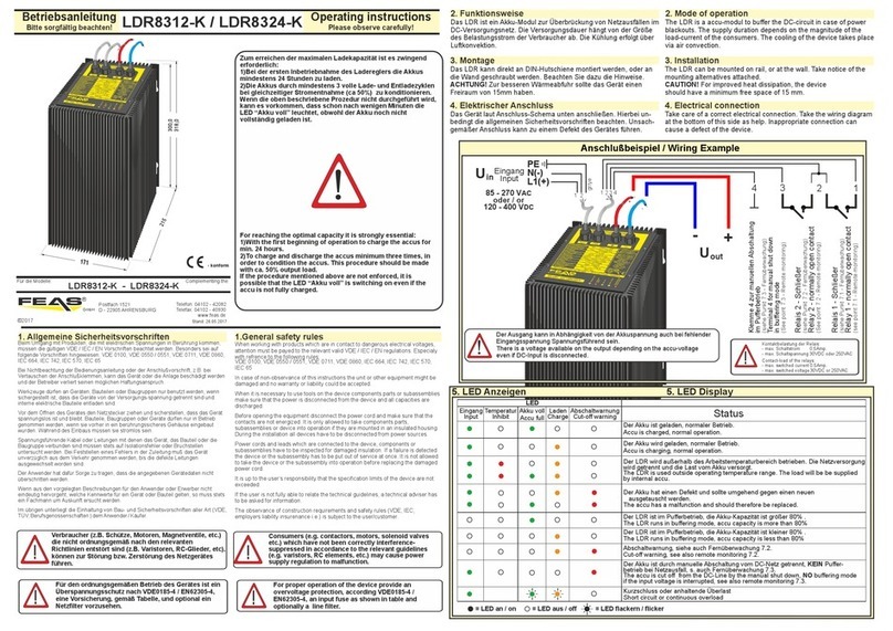
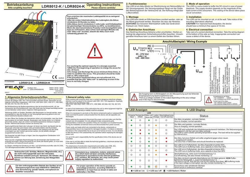
Eingang
DC-Input
Uout
Uin
DC-Ausgang
DC-output
+
-
L1
N
Klemme 1-2
Manuelle Lasttrennung
Terminal 1-2
Manual load disconnection
85 - 270 VAC
oder / or
120 - 400 VDC
1
2
PE
Klemme 3-4 zur manuellen Abschaltung
des Geräts / „Schlafen legen“ im Pufferbetrieb
(zur Schonung des Akkus)
Terminal 3-4 for manual shut down/
switching to „sleeping“ in buffering mode
(to maintain the battery)
3
4
Anschlussbeispiel/ Wiring Example
5.2 RS-485 - Betrieb / Abschlusswiderstand
Vor Inbetriebnahme des LDR über die RS-485-Schnittstelle
müssen die Pins 3-5 verbunden werden.
Außerdem muss ein Abschlusswiderstand zwischen den
Pins 7-8 angebracht werden. Erfahrungsgemäß reicht ein 120Ω
Widerstand. Mit zusätzlicher Kabellänge kann sich der
Widerstandswert erhöhen (siehe entsprechende Richtlinien im
Internet).
5.1 RS-485 Operation
For running the LDR with via the RS-485-interface connect PIN 6
and PIN 7 before first operation.
A terminating resistor has to be inserted between pins 7-8.
Typically a 120Ω resistor is sufficient. With additional cable length,
the resistance value may increase (see corresponding guidelines
on the Internet).
6.1 Abschaltung Ausgang
Über die RS-Schnittstelle kann die Ausgangsspannung
freigegeben oder abgeschaltet werden.
Eine manuelle Lasttrennung ist über die Klemmen 1-2 am LDR
möglich.
6.1 DC off
Via the RS interface the DC output can be switched on or off.
The load can be manually disconnected via the terminals 1-2 of
the LDR.
Ansicht von außen/outer view
D-Sub 9-polig Buchse (female)/
D-Sub 9-pin socket (female)
5432 1
6789
5.3 RS-232/RS-485 jack assignment5.3 RS-232/RS-485 Buchsenbelegung
Pin Pinconnection connection
TxD RS232 n.c.
n.c.
Output
Intput
GND
Spannung
RS-485 DATA
RxD RS232
n.c.
GND GND
n.c.
A
B
desciption desciption
1 1
2 2
3 3
4 4
5 5
6 6
7 7
8 8
n.c.
GND_485
n.c.
9n.c. 9U+
GND_RS485
RS-485 DATA
5.1 RS-232 - Betrieb
Vor Inbetriebnahme des LDR über die RS-232-Schnittstelle
müssen die Pins 3-5 und 4-5 verbunden werden.
5.1 RS-232 Operation
For running the LDR with via the RS-232-interface connect PINs 3-
5-4 before first operation. 6.2 Vollständiges Abschalten des LDR
Zum vollständigen Abschalten das LDR vom Netz trennen und
warten, bis das LDR den Pufferbetrieb aufgenommen hat.
Danach die Klemmen 3 und 4 für ca. 15 Sekunden verbinden.
So wird das Gerät vollständig abgeschaltet (“Schlafen gelegt“)
und erst mit Einschalten der Eingangsspannung wieder
aktiviert.
6.2 Complete shutting down of the LDR
To shut down completely, disconnect the LDR from mains
supply and wait until LDR switches to buffering mode.
Then connect terminals 3 and 4 for approx. 15 seconds.
Then the unit is completely switched off ("sleeping mode") and
will only be reactivated when the input voltage is switched on.
6. Abschaltfunktionen 6. Shutdown Functions
120 Ω
5.4 RS-232/RS-485 connector pin assignment5.4 RS-232/RS-485 Steckerbelegung
bridge
bridge
bridge
Der Ausgang kann in Abhängigkeit von der Akkuspannung auch bei fehlender Eingangsspannung spannungsführend sein.
There is a voltage available on the output depending on the accu-voltage even if DC-Input is disconnected.
!
RS-232 RS-485

7. RS-232 / RS-485 Betrieb 7. RS-232 / RS-485 Operation
Wertebereich / Bedeutung
(Screenshots siehe nächste Seiten)
Parameter
Current
activity:
Remaining
Time:
Battery
Voltage:
Present
Load Current:
Battery
Temperature:
Device
Temperature:
Remaining
Capacitiy:
Present
Wear Level:
Warnings:
- CHARGE BATTERY (Batterie wird geladen)
- BATTERY FULL (Batterie voll geladen)
- DISCHARGE BATTERY (Batterie wird entladen)
- EPROM RESET (bei Batterietausch/Wartung)
- Switch OFF completed
(“Schlafenlegen“ aus Pufferbetrieb)
Zusätzlich werden angezeigt:
- NO LINE VOLTAGE (kein Netz)
- DC OFF (Last abgeschaltet)
- Short Circuit (Kurzschluss)
- OVERLOAD (Überlast)
- DEEP DISCHARGED
(Batterie ist tiefentladen, Last getrennt)
- LINE ON. Battery damaged
(Netz vorhanden Batterie defekt)
- Battery Over Temperature
(Akku zu heiß, Last getrennt)
z.B. 999 [min] (maximale Zeit, diese ist abhängig
von der „max. possible Time“, die vom Kunden
eingestellt wird - d.h. für die hohe Belastung ist
eher „Remaining Time“ und für die niedrige Belas-
tung „max. possible Time“ die richtige Auswahl)
Hier wird nur die Akkuspannung angezeigt
(nicht die Ausgangsspannung)
Hier wird der Laststrom angezeigt
Hier wird die Akkutemperatur angezeigt
Hier wird die Gerätetemperatur angezeigt
Verbleibende Akkukapazität
Aktueller Verschleißgrad des Akkus
hier werden die Zustände angezeigt wie Über-
temperatur, Überlast, Kurzschluss + dazu
„FUSE MODE“, wenn dieser aktiv ist.
Value range / definition
(screenshots see next pages)
Parameter
Current
activity:
Remaining
Time:
Battery
Voltage:
Battery
Temperature:
Device
Temperature:
Remaining
Capacitiy:
Present
Wear Level:
Warnings:
- CHARGE BATTERY (battery is charging)
- BATTERY FULL (battery fully charged)
- DISCHARGE BATTERY (battery is discharged)
- EPROM RESET
(during battery replacement/maintenance)
- Switch OFF completed
(switching to „sleeping“ from buffer mode)
Additionally displayed:
- NO LINE VOLTAGE (no mains)
- DC OFF (load switched off)
- Short Circuit
- OVERLOAD
- DEEP DISCHARGED
(battery is deeply discharged, DC off)
- LINE ON. Battery damaged
- Battery Over Temperature (DC off)
e.g. 999 [min] (maximum time, this depends
on the "max. possible time" set by the
customer - that means, for the high load
preferably "RemainingTime" is the right choice
and for the lower load "max. possible time")
Here the battery voltage
(and not the output voltage) is displayed
Here the load current is displayed
Here the accutemperature is displayed
Here the devicetemperature is displayed
Here the remaining accu capacity is displayed
Here the actuell degree of wear is displayed
Here conditions are displayed such as
Overtemperatur, Overload, Short circuit,
and „FUSE MODE“ if activated
Current
Mode:
Current
Mode:
- NORMAL
- FUSE (Fuse Mode ist aktiviert)
- NORMAL
- FUSE (fuse mode is activated)
Selected
Buffering
Time:
Selected
Buffering
Time:
Hier wird nur die ausgewählte Pufferzeit
angezeigt Here the chosen buffering time is displayed
„O“ „O“
„S“ „S“
„F“ „F“
„N“ „N“
„T“ „T“
„L“ „L“
„A“ „A“
Ausgangslast trennen Disconnect Outputload
Ausgangslast nach trennen wieder zuschalten Outputload switch on again
Fuse-Mode aktivieren / deaktivieren
(siehe Kapitel 12)
Activate / deactivate fuse mode
(see chapter 12)
Normal Mode Regular mode
Einstellung der max. Betriebszeit bei Laden
und getrennter Last - schnell eingeben!
Setting the max. Operating time when loading
and separated load - enter quickly!
Verlassen von Menü der max. Betriebszeit Leaving the menu of the max. operating time
LDR80-RS deaktivieren (“Schlafen legen“)
Nur im Entladevorgang bei getrennter Last.
Disable LDR80-RS (sleep-mode) Only in the
unloading process with separated load.
Über die RS-232/RS-485-Schnittstelle gibt das LDR
Statusmeldungen aus und nimmt Kommandos entgegen.
Dazu muss das LDR über ein spezielles RS-232- oder RS-
485-Kabel mit einem PC verbunden sein (siehe Abschnitt 5).
Auf dem PC muss ein Terminalprogramm gestartet werden
(z.B. das kostenlose Programm: PuTTY).
Die Verbindungsparameter sind entsprechend der unten
stehenden Tabelle zu wählen.
Via the RS-232 / RS-485 interface the LDR sends
status messages and accepts commands.
For this purpose, the LDR must be connected to a PC via a
special RS-232 or RS-485 cable (see section 5).
On the PC a terminal program has to be started (for example
the free program: PuTTY).
The interface settings must correspond to the table
below.
8. Screen displays8. Bildschirmanzeigen
9. RS-232 / RS485 Commands9. RS-232- / RS-485-Befehle
Present
Load Current:
Verbindungsparameter Interface settings
Baudrate
Datenbits
Stoppbits
Parität
Flusssteuerung
Baud-rate
Data bits
Stopp bits
Parity
Flow control
19200 bps19200 bps
8
1
keine
XON / XOFF XON / XOFF
19200 bps19200 bps
8
1
none
Bedeutung Meaning

Kein Netz, Pufferbetrieb,
Last am DC-Ausgang freigegeben
No line voltage, operation with battery load,
load DC on
Ladebetrieb, getrennte Last am Ausgang
Charge Operation, DC OFF
Batterie voll geladen, Erhaltungsladung,
Last am DC-Ausgang freigegeben
Battery fully charged, trickle charging,
load DC on
Kein Netz, Last am Ausgang getrennt,
trotzdem geringfügige Batterieentladung
No line voltage, DC is switched off,
nevertheless slight battery discharge
Ladebetrieb, Last am DC-Ausgang freigegeben
Charge Operation, DC on
Die Bildschirmanzeigen für RS-232 und RS-485
unterscheiden sich nur in der Kopfzeile:
RS-232: “FEAS BATTERY CONTROL – RS232“
RS-485: „FEAS BATTERY CONTROL – RS485“
The screen displays for RS-232 and RS-485 differ only in the
header:
RS-232: "FEAS BATTERY CONTROL - RS232"
RS-485: "FEAS BATTERY CONTROL - RS485"
10. RS-232/RS-485-Anzeigen im Detail 10. RS-232/RS-485 screen displays in detail

Pufferzeiteinstellung, Erhöhung der Zeit
Setting Remaining Time, increasing time
Ladebetrieb, getrennte Last
Einstellung der Pufferzeit
Charge Operation, DC OFF
Setting of remain time
Zurücksetzen des Gerätes beim Einsatz von neuen
Akkus
How to reset the device when using new batteries
Pufferzeiteinstellung - Reduzierung der Zeit
Setting Remaining Time - decreasing time
„Schlafen legen“ im Pufferbetrieb
Switching to „sleeping“ in buffering mode
11. RS-232/RS-485-Einstellungen im Detail 11. RS-232/RS-485 Settings in detail
Im Pufferbetrieb kann das LDR zur Schonung des Akkus
deaktiviert werden (“Schlafen gelegt“).
Diese Anzeige erscheint auch nach einer bestimmten Anzahl
von Kurzschluss- / Überlastereignissen im Pufferbetrieb.
In buffer mode, the LDR can be deactivated ("sleep mode") to
maintain the battery.
This display also appears after a certain number of short-
circuit / overload events in buffer operation.
Die Pufferzeiteinstellung ist nur im Netzbetrieb und bei
getrennter Last möglich.
Für die Eingabe der Pufferzeit folgen Sie bitte den
Anweisungen im Menü.
Die Veränderung der Pufferzeit erfolgt durch Addition or
Subtraktion von 1, 5, 10, 25, 50 oder 100 Minuten
(siehe auf Abbildung: „... please press ‘A‘=1, ‘S‘=5, ...“).
The buffer time setting is only possible in mains operation
and when the load is disconnected.
To enter the buffer time, please follow the instructions
in the menu.
The buffer time is changed by addition or subtraction of
1, 5, 10, 25, 50 or 100 minutes
(see on screenshot: „... please press ‘A‘=1, ‘S‘=5, ...“).
Pufferzeiteinstellungsende
End of Remaining Time Setting
Batteriewechsel siehe Abschnitt 14 Battery replacement see chapter 14

12. Betriebshinweise / Schutzschaltungen
a) Thermischer Akku-Schutz
Um die eingebauten Akkus vor zu starker Erwärmung zu schützen,
ist das LDR mit einem thermischen Schutz für Akkus
ausgerüstet.
Übersteigt die Akkutemperatur einen kritischen Wert, können die
Akkus nicht mehr geladen bzw. nachgeladen werden.
In diesem Fall ist kein voller Pufferbetrieb gewährleistet. Befindet
sich das Gerät im Pufferbetrieb, so wird die Last getrennt.
Aus diesem Grunde bitte für ausreichende Kühlung sorgen!
b) Schutz vor Tiefentladung
Sinkt die Akkuspannung im Pufferbetrieb unter einen kritischen
Wert von 21,0V (24V-Version), wird die Ausgangsspannung
automatisch abgeschaltet, um die Akkus vor “Tiefenentladung”
zu schützen. Im RS-232/RS-485-Betrieb erfolgt eine Meldung an
den Rechner. Danach wechselt der LDR in den Schlafmodus.
c) Interne Strombegrenzung / zeitlich dynamischer
Boostbetrieb
Zum Schutz des Gerätes besitzt das LDR eine interne
Strombegrenzung von max. 120%. Dem Anwender steht für eine
begrenzte Zeit eine Leistung über 100% zur Verfügung.
Die Verweilzeit, in der sich das Gerät im Boostbetrieb befindet,
hängt von der Höhe des Ausgangsüberlaststromes ab.
Nach Ablauf dieser Zeit trennt das Gerät die Last und schaltet
diese anschließend wieder automatisch zu.
d) Die Auszeit für die Erholung des Gerätes, ausgelöst durch
Überlast oder Kurzschluss ist abhängig von der Anzahl der
Ereignisse (je mehr Ereignisse, umso länger die Auszeit).
Bei einer gewissen Anzahl der Ereignisse
- schaltet sich das Gerät aus (im Pufferbetrieb) bzw.
- trennt die Last (im Ladebetrieb, siehe LED-Anzeige).
f) Fuse Mode
Über die RS-Schnittstelle kann Fuse-Mode aktiviert werden.
Wenn die interne Sicherung dann ausgelöst wird, schaltet das
Gerät die Last dauerhaft ab.
Ein Neustart ist erst nach manuellem Einschalten möglich.
e) Um das Gerät zu reaktivieren,
muss das Gerät von der Hauptstromversorgung getrennt
werden.
Das Gerät wird automatisch in den Schlafmodus versetzt und kann
nach ca. 1 Minute wieder durch das Zuschalten der
Hauptstromversorgung reaktiviert werden.
12. Operation notes / Protective shutdowns
a) Thermal battery protection
In order to protect the built-in storage batteries from inadmissible
heating, the LDR is equipped with a thermal protection for the
accumulators.
This charge protection has the effect that the accumulators won’t
be charged or recharged anymore. Full buffering mode is not
possible.
In case of indadmissable heating during buffering mode, the DC
output will be shuted down.
For this reason please provide for sufficient cooling!
b) Protection against deep discharge of the battery
If the voltage of the accumulator decreases below a critical value
of 21,0V (24V Version) the output voltage will be disconnected
automatically in order to protect the storage battery against “Deep
Discharge”. Via the RS interface the LDR sends a message to the
computer. Afterwards the LDR changes to sleeping mode.
c) Internal Current Limit / dynamic boost mode
To protect the unit, the LDR has an internal current limitation of
max. 120%. Power above 100% is available to the user for a
limited time. The duration of the boost mode depends on the level
of the output overload current.
After this time has elapsed, the unit disconnects the load and
then reconnects it automatically.
d) The time-out for recovery of the device (triggered by overload
or short-circuit) depends on the number of events (the more
events, the longer the time-out).
After a certain number of events
- the device switches off (in buffer mode) or
- disconnects the load (in charging mode, see LED display).
f) Fusemode
Fuse mode can be activated via the RS interface. If the internal
fuse is then triggered, the unit immediately switches off the load
durably. A restart is only possible after manual switch-on.
e) In order to reactivate the device,
the device must be disconnected from the main power supply.
The device is automatically put into sleep mode and can be
reactivated after about 1 minute by switching on the main power
supply.
14. Batteriewechsel
Der Akku wird automatisch in regelmäßigen Abständen auf
einwandfreien Zustand getestet. Ein defekter Akku wird durch
LEDs angezeigt (siehe LED-Anzeige).
Der Akkutausch sollte bei einer Temperatur von ca. 20°C-25°C
erfolgen, da sonst am Rechner falsche Werte angezeigt
werden können.
Schritt 1: Eingangsspannung ausschalten.
Schritt 2: Gerät auf den Kopf stellen.
Schritt 3: Die 7 Inbusschrauben (M4) von der Bodenplatte lösen.
Schritt 4: Akkus herausnehmen und die Kabel von den
Kontakten abziehen.
Schritt 5: Die Akku-Anschlusskabel am Gerät Achtung!
müssen voneinander isoliert werden, damit es nicht
zu einem Kurzschluss kommen kann!
Danach Gerät an die Netzspannung anschließen und
warten, bis alle LEDs blinken.
Danach von der Netzspannung trennen.
Damit ist die Batteriezustandsanzeige zurückgesetzt.
Wenn das Gerät am Rechner angeschlossen ist,
siehe Screenshot, Kapitel 11: „Zurücksetzen des
Gerätes“.
Danach etwa 1 Minute ohne Strom lassen
(damit alle Kondensatoren entladen werden).
Schritt 6: Neue Akkus an die Kabel anschließen (Auf korrekte
Polarität achten! Rote Kabel zum Plus-Pol, blaue Kabel
zum Minus-Pol des Akkus)
Schritt 7: Akkus in den Batterieraum schieben.
Schritt 8: Bodenplatte wieder aufschrauben.
Schritt 9: Die alten Akkus ordnungsgemäß und umwelt-
gerecht entsorgen!
Die Lebensdauer der Akkus hängt laut Akku-Hersteller von der
Anzahl der Lade- und Entladezyklen, des Entladestroms und der
Temperatur ab (0°C bis 20°C ca. 5 Jahre, ab ca. 25 °C
Reduzierung der Lebensdauer bei voll geladener Batterie).
15.Battery replacement
The battery will be tested automatically for normal condition in
constant intervals. A defect battery is reported by LEDs (see
LED-Display).
The battery exchange should take place at a temperature of
approx. 20°C-25°C. Otherwise wrong values can be indicated
at the computer.
Step 1: Switch off input voltage.
Step 2: Place device on its upper surface.
Step 3: Screw off the 7 Allen screws (M4) from the base plate.
Step 4: Remove storage batteries and pull the cables
from the contacts.
Step 5: The battery connection cables on the unit Attention!
must be insulated from each other to prevent a short
circuit!
Then connect the device with supply voltage
and wait until all LEDs are flashing.
Disconnect afterwards.
So battery wear level is reseted to 100%.
If the device is connected to the computer, see screenshot
on page 11, „How to reset the device“
Leave for about 1 minute without power
(so that all capacitors are discharged).
Step 6: Connect new storage batteries to the cables
(Note polarity! Red cable to the positive terminal
of the storage battery).
Step 7: Slide storage batteries into the battery compartment.
Step 8: Screw base plate back again.
Step 9: Dispose of the old storage batteries properly and
environmentally safely!
According to the battery manufacturer, the battery life depends on
the number of charging and discharging cycles, the discharge
current and the temperature (0°C - 20°C approx. 5 years, from
approx. 25 °C reduction of the service life with fully charged
battery).
Eine Verpolung der Akkus beim Einsetzen führt unweigerlich
zur Zerstörung des Gerätes und ist nicht reparabel und führt
zum Erlöschen der Gewährleitungsansprüche.
Reverse polarity of battery causes the damage of the
device and is not repairable.
This leads to termination of warranty.
Batteriewechsel / Battery replacement
Accu 2
Accu 1
+
-
+
-
24V-Version
Remove here the
screws M4 with
Inbus-key(SW2,5)!
device
e.g. SNT230
Grobschutz
Surge protective
devices
Typ1
>1300V
Mittelschutz
Surge protective
devices
Typ2
>600V
Feinschutz
Surge protective
devices
Typ3
<600V
Netzfilter
linefilter
e.g.
FEAS NFK
VDE0185-4 / EN62305-4
Überspannungs- und Transientenschutz
Overvoltage and Transientprotection
Blitz- und Transientenschutz
lightning and overvoltage protection
EMV Schutz
EMC protection
Aufgrund der internen Transienten-Schutzschaltung
sollte die Isolationsprüfung Ihrer Anlage nicht mit
unserem Gerät erfolgen.
Due to the internal transient protection circuit, the insulation
test of your system should not be carried out with our device.
!
13. Wartung
Zur Vermeidung eines Unfalls müssen im Falle der
Wartung oder Fehlerbehebung (z.B. Kurzschluss auf
der Sekundärseite) die Versorgungszuleitungen auf
der Primär-/ Sekundärseite von den Klemmen
getrennt werden. Die Erdung darf nicht entfernt
werden.
13. Mainenance
To avoid an accident in case of maintenance or
troubleshooting (for example short circuit on the
secondary side) the electrical supply on the
primary / secondary side must be disconnected
from the terminals. The earthing must not be
removed.
!
!
!

Eingangsspannung
Input voltage
Kapazität
Capacity
Typ
Ausgangsspannung
folgt der Akkuspannung (U )
Puffer
Outputvoltage
follows the accu voltage (U )
buffer
85V ...270V / 120V ....400V
AC AC DC DC
LDR8024-RS
21,0 - 27,6 VDC
10A (Boost max.12A)
Ausgangsstrom
Output current
Pufferzeit
Hold-up-time typ. 10A 40min
7Ah
16. Technische Daten
Schutzeinrichtungen
bei 115V 5,0A träge / bei 230V 2,5A träge
AC AC
nicht erforderlich, da kurzschlussfest
im Gerät integriert
Vorsicherung (nur Empfohlen)
Ausgangssicherung
Überlastschutz
Mechanik
Abmessungen (B x H x T) 171mm x 196mm x 215mm
Gewicht ca. 12,2kg
Wandmontage mit Schrauben M8
Befestigung
Eingangsgrößen
85 - 270 V (44- 66Hz)
AC
120 - 400 VDC
bei 115 V max. 3,0A / bei 230 V max. 1,5A
AC AC
<8A bei 230 VAC
Eingangswechselspannung
Eingangsgleichspannung
Stromaufnahme bei Nennlast
Einschaltstromstoß
Schutzbeschaltung
Sicherheitsdaten
Prüfspannung Trafo 5 kV gemäß VDE0570
AC
Hochspannungsfestigkeit Eingang/Ausgang 4 kV gemäß VDE/IEC
AC
L/N - PE = 1500V zusätzlich begrenzt durch
AC
interne Schutzbeschaltung
out - PE = 500V
DC
Funkentstörgrad gemäß VDE0871B, EN55022/B
95% relative Feuchte im Jahresdurchschnitt
Betauung möglich - tropentauglich
IP65
Schutzklasse
Umgebungsfeuchte
Schutzart Gehäuse
Klasse I, mit PE-Anschluss (EN62368)
Schutzart Klemmen IP20 (BGV A3)
Rüttelfestigkeit >30g bei 33Hz in X, Y und Z
nach IEC68 und DIN41640
Schutzkleinspannung PELV (EN60204), SELV (EN62368)
ca. 91% (Netzbetrieb)Wirkungsgrad
Betriebsdaten
100% (Dauerbetrieb)
ab 40°C
Einschaltdauer (ED)
Leistungsabweichung bei Temperatur
-20°C bis +50°C
-20°C bis +50°C
Lagertemperaturbereich
Arbeitstemperaturbereich
natürliche Konvektion
Blei-Gel-Akku
Kühlung
Akku-Typ
Parallelschaltbar Nein
Aufstellungshöhe
MTBF
unbegrenzt
> 380.000h (ohne Akku)
Pufferzeit
Kapazität C
siehe Tabelle unten
7,0 Ah (20°C)
Angewandte Bauvorschriften
CSA/UL CSA-C 22.2 / UL60950, UL508, UL1950
gemäß VDE
IEC
EN
VDE0100, VDE0110, VDE0113, VDE0551,
VDE0806
IEC62368-1, IEC61000-6-1-2-3-4, IEC60068-2-3,
EN62368-1 EN61000-6-1 EN61000-6-2
EN61000-6-3, EN61000-6-4, EN55022, EN55011
EN61000-3-2, EN61000-3-3, EN60204 EN61140
EN60529, EN61000-4-2-3-4-5-6-8-11, EN60068-1
EN6068-2-1, EN61558-2-17
EN61010-1
IEC60068-2-11-52, IEC60529
Regelgrößen
<200 mV bei Laständerung 10 ... 90%
<25 mV bei Netzspannungsänderung ±10%
<10ms bei Laständerung 10 ... 90%
Regelabweichung (Last)
Regelabweichung (Netz)
Regelzeit
Ausgangsgrößen
siehe Tabelle unten oder Geräteaufdruck
siehe Tabelle unten oder Geräteaufdruck
Ausgangsspannung UNenn
Ausgangsstrom INenn
Strombegrenzung
Restwelligkeit
max. 1,2 x I , dynamisch zeitlich begrenzt
Nenn
<50mVrms
Leistung max. 320 Watt
Status-Meldung / Fernsteuerung
Datenaustausch, Netz, Temp., Akku voll, Laden,
Abschaltwarnung
Siehe Tabelle Kapitel 8
Statusanzeigen / LEDs
RS-232/ RS-485-Meldungen
16. Technical Data
Y-Transient voltage suppressor Varistor
test voltage limited by surge arrester
Input current peak
Output voltage UNom.
Input voltage AC
Inputvoltage DC
Protective circuit
Input current at nominal load
at 115V 5,0A delayed / at 230V 2,5A delayed
AC AC
85 - 270 V (44 - 66Hz)
AC
120 - 400 VDC
bei 115 V max. 3,0A / bei 230 V max. 1,50A
AC AC
<8,0 A bei 230 VAC
Ip65 / Ip20 (VGB4)
PELV (EN60204), SELV (EN62368)
ca. 91% (Line operation)Efficiency
100% (continuous operation)
-20°C bis +50°C
-20°C bis +50°C
Connected in parallel No
Installation height
MTBF
unlimited
Buffertime
Capacity
CSA/UL CSA-C 22.2 / UL60950, UL508, UL1950
IEC
EN
VDE0100, VDE0110, VDE0113, VDE0551,
VDE0806
IEC62368-1, IEC61000-6-1-2-3-4, IEC60068-2-3,
EN62368-1 EN61000-6-1 EN61000-6-2
EN61000-6-3, EN61000-6-4, EN55022, EN55011
EN61000-3-2, EN61000-3-3, EN60204 EN61140
EN60529, EN61000-4-2-3-4-5-6-8-11, EN60068-1
EN6068-2-1, EN61558-2-17
EN61010-1
IEC60068-2-11-52, IEC60529
max. 1,2 x I dynamic boost operation
Nom.,
<50mVrms
Power max. 320 Watt
Status messages / remote control
Data transfer, input, battery full, charging,
cutt-off-warning
see tabel in chapter 8
Status indicator / LED
Messages
1 RS-232/RS-485 auf D-Sub 9-pol-Buchse
Schnittstellen 1 RS-232/RS-485 on D-Sub 9-pin socket
Interfaces
Input data
Output data
see table or face plate of device
see table or face plate of device
7,0 Ah (20°C)
see table below
Output current INom.
Current limiting
Residual ripple
Control data (DC power supply)
Control deviation load
Control deviation supply
Control time
< 200mV with load variation 10...90%
< 25mV with supply variation ±10%
< 10 mSek. with load variation 10...90%
Operating data
Duty circle
Operating temperature range
Derating from 40°C
Storage temperature range
Cooling selfcooling
Lead-acid accumulator
>380,000 h without storage battery
Safety devices
Fuse for input (only recommended)
Fuse for output not necessary, cont. short circuit proof
Overload protection integrated into the device
Safety data
Test voltage transformer
High voltage resistance
Degree of EMI suppresion
Protection class
Ambient humidity
Protective class enclosure / Terminals
Vibration proof
Extra low safety potential
5 kVac in accordance to VDE 0570
Primary circuit - secondary circuit 4 kVac
L/N - PE = 1500V additionally limited by
AC
internal protection circuit
out - PE = 500VDC
acc. to VDE 0806 / IEC 380
acc. to IEC 60068-2-27 without storage battery
in acc. to VDE 0871 B, EN 55022/B
Class 1, with PE connection (EN 62368)
95% relative humidity, yearly average dewing
allowed for use in tropical ambient
>30g at 33Hz in X,Y and Z,
Applied construction regulations
according to VDE
Mechanics
Mounting
Dimensions
Weight
wallmounting with screws M8
171mm x 196mm x 215mm (WxHxD)
approx. 12,2kg
Kapazität in % zur Nennkapazität bei verschiedenen
100
0°C
20°C
-10°C
-20°C
80
60
40
20
0
2 4 6 8 10 12 14
Kapazität - Capacity (% C) è
è
anliegender Laststrom - Load current (Amp.)
Akku-type
- LED schnelles blinken / LED flashing fast
Laden
Battery charging
Eingang
Supply Voltage Temperatur
Over temperature Akku voll
Battery OK Abschaltwarnung
Battery Cutt-off Datenaustausch
Data transfer DC - Ausgang
Voltage output
Erreigniss - Event
aus / off
Erstes Einschalten
First switch ON
10sec. nach Einschalten
10sec. after switch ON. aus / off
Netz da, Akku voll
Line available, Battery full. an / on
Netz da, Akku laden
Line available, Battery charging.
Netz da, Akku defekt
Line available, Battery fault.
an / on
an / on
Netz da, Überlast
Line available, Overload.
aus / off
Netz da, Kurzschluss.
Line available, Output short circuit.
an / on
Netz da, Überlast, abgeschaltet
Line available, Overload, off. aus / off
Netz da, Ta > 51°C
Line available, Ta > 51°C. an / on
Netz da, Ta > 53°C
Line available, Ta > 53°C.
Netz da, Ta > 55°C
Line available, Ta > 55°C.
an / on
aus / off
Netz da, Kurzschluss.
Line available, Output short circuit.
Netz da, Überlast
Line available, Overload.
Netz da, Überlast, abgeschaltet
Line available, Overload, off.
Netz da, Ta > 51°C
Line available, Ta > 51°C.
Netz da, Ta > 53°C
Line available, Ta > 53°C.
Netz da, Ta > 55°C
Line available, Ta > 55°C.
aus / off
an / on
aus / off
an / on
an / on
aus / off
Netz aus, Akku voll
Line off, Battery full. an / on
Netz aus, Akku leer
Line off, Battery empty. an / on
Netz aus, Akku entladen.1sec
Line off, Battery discharged.1sec. aus / off
aus / off
Netz aus, Akku entladen
Line off, Battery discharged.
Netz aus, Akku defekt
Line off, Battery fault. an / on
Netz aus, Kurzschluss
Line off, Output short circuit. aus / off
Netz aus, Überlast
Line off, Overload. an / on
Netz aus, Überlast, abgeschaltet
Line off, Overload, off. aus / off
Netz aus, Ta > 51°C
Line off, Ta > 51°C. an / on
Netz aus, Ta > 53°C
Line off, Ta > 53°C. an / on
Netz aus, Ta > 55°C
Line off, Ta > 55°C. aus / off
Netz aus, Ta < 45°C
Line off, Ta < 45°C. an / on
- LED an / LED on - LED aus / LED off
- LED aufsteigend blinken / LED flashing with increasing intensity
- LED blinken abwechselnd / LED flashing alternate
- LED absteigend blinken / LED flashing with decreasing intensity
Tg - Temperatur im Gerät / Device temperature. Ta - Akku - Temperatur / Battery temperature.
- LED langsames blinken / LED flashing slowly
15. LED Anzeigen - LED Display LDR80-RS
Netz da / Line on, Last aus /DC off
after permanent short circuit aus / off
Y-Transientenüberspannungsschutz Varistor, Gas-
ableiter gegen PE, durch Prüfspannung begrenzt

© 2019
Postfach 1521
D - 22905 Ahrensburg
Telefon: +49 4102 42082
Fax: +49 4102 40930
E-Mail: [email protected]
Internet: www.feas.de
SSE2405
Puffermodul
Art.Nr.: 622405
Ÿ Gleichspannungspuffermodul für 24 VDC Netz
Ÿ Sicherheitskleinspannung
Ÿ Überlast- und Leerlaufsicher
Ÿ Kurzschlussfest
Ÿ Parallelschaltbar
Ÿ Keine Akkus verbaut - wartungsfrei
Ÿ LED-Betriebsanzeige
Ÿ Relais für Fernüberwachung der
Spannungsversorgung
Ÿ· Tropentauglich durch Gießharzvollverguss
Ÿ· Sicherheit nach VDE, EN, UL CSA
LDR30MH24
Mini DC-USV für die Hutschiene
Art.Nr.: 589960
Ÿ3 in 1 - vereint Schaltnetzteil, Ladekontrolleinheit und Akku in
einem sehr kompakten Gehäuse
ŸPufferung eines Verbrauchers bei Netzausfall
ŸPufferzeit begrenzbar (1-20 Minuten und unbegrenzt)
ŸIm Pufferbetrieb manuell abschaltbar, “Schlafenlegen”
ŸIntegrierter NiMH Akkumulator mit 0,72 Ah (austauschbar)
ŸMikroprozessorgesteuerte Akkumulator-Überwachung und
Ladeanzeige
ŸLED-Anzeigen für Netzausfall, Überlast und Übertemperatur
ŸRelais-Meldung von Netzausfall, Übertemperatur, Akku-
Defekt und Akkuspannung kritisch
ŸBoostfunktion: 150% Iout bis zu 30s
ŸKurzschlussfest, überlast- und leerlaufsicher
ŸAusgang potentialfrei nach VDE 0551
ŸSicherheit nach VDE, EN, UL und CSA
151,5
9,5 9,5
25,0
Geeignet für M8 Schrauben
Suitable for M8 screws
GmbH
Postfach 1521
D - 22905 AHRENSBURG
Telefon: 04102 - 42082
Telefax: 04102 - 40930
www.feas.de
© 2012 ®
Klemmen / terminals
120 mm
25 mm 25 mm
LDR80
Maße Rückseite - Dimensions backside
175 mm
Table of contents
Other FEAS Power Supply manuals
Popular Power Supply manuals by other brands
IFM
IFM ecomat300 AC1220 installation instructions
JVA
JVA Z28 Installation and user manual

thomann
thomann Harley Benton Powerplant user manual

Mitsubishi Electric
Mitsubishi Electric PAC-SC50KUA installation manual
ZALMAN
ZALMAN ARX Series user manual

CRYOMAGNETICS
CRYOMAGNETICS 4G Operating instructions manual
