FEAS SNT230 User manual

Betriebsanleitung
Bitte sorgfältig beachten!
Operating
instructions
Please observe carefully!
SNT230
SNT23012 - SNT23024 - SNT23048
Für die Modelle: For the Types:
- konform
GmbH Postfach 1521
D - 22905 AHRENSBURG Telefon: 04102 - 42082
Telefax: 04102 - 40930
www.feas.de
©2017
®
Stand: 24.07.2017
- 1 -
Schutzeinrichtungen
bei 400VAC 10Amp. träge
nicht erforderlich, da kurzschlussfest
im Gerät integriert
Ausgangssicherung
Überlastschutz
Eingangsgrößen 320 - 576V (44 - 400Hz)
AC
350 - 572V (44 - 400Hz)
AC
450 - 810VDC
bei 400VAC max. 2,9A
<12,0 A bei 550VAC
Transientenüberspannungsschutz-Varistor
Eingangswechselspannung (3-Phasenbetr.)
Eingangswechselspannung (2-Phasenbetr.)
Eingangsgleichspannung
Stromaufnahme bei Nennlast
Einschaltstromstoß
Schutzbeschaltung
Sicherheitsdaten
Prüfspannung Trafo
5kV gemäß VDE0570
AC
Hochspannungsfestigkeit
Eingang/Ausgang 4,4kV nach VDE0806/IEC380
AC
Funkentstörgrad
gemäß VDE0871B, EN55022/B
95% relative Feuchte im Jahresdurchschnitt
Betauung möglich - tropentauglich
IP68
Schutzklasse
Umgebungsfeuchte
Schutzart Gehäuse
Schutzklasse I mit PE-Anschluss (EN60950)
Schutzart Klemmen
IP20 (BGV A3)
Rüttelfestigkeit
>100g bei 33Hz in X, Y und Z
nach IEC68 und DIN41640
Schutzkleinspannung
PELV (EN60204), SELV (EN60950)
Betriebsdaten
100% (Dauerbetrieb)
-40°C bis +80°C
Einschaltdauer (ED)
Arbeitstemperaturbereich
-40°C bis +105°C
Ja
ab 40°C
Lagertemperaturbereich
Parallelschaltbar
Leistungsabweichung bei Temperatur
natürliche Konvektion
Kühlung
Wirkungsgrad
siehe Tabelle
Aufstellungshöhe
MTBF
unbegrenzt
> 380.000h
Angewandte Bauvorschriften
CSA/UL
CSA-C 22.2 / Ul60950, Ul508, UL1950
gemäß VDE
IEC
EN
VDE0100, VDE0110, VDE0113, VDE0551,
VDE0160/W2, VDE0806
IEC60950, IEC61000-6-1-2-3-4, IEC60068-2-3,
EN60950-1, EN61140, EN61000-6-1, EN61000-6-2,
EN61000-6-3, EN61000-6-4, EN55022, EN55011
EN61000-3-2, EN61000-3-3, EN50204, EN60204
EN60529, EN61000-4-2-3-4-5-6-8-11, EN60068-1,
EN6068-2-1-2-3-6-27-30, EN45501, EN50021,
EN61558-2-17, EN50178
IEC60068-2-11-52, IEC60529, IEC380
Ausgangsgrößen siehe Tabelle
siehe Tabelle
einstellbar 0,5 .......I und Hinweis Seite 5
max.
Ausgangsspannung UNenn
Ausgangsstrom INenn
Strombegrenzung
Leistung
Restwelligkeit (20MHz Bandbreite)
siehe Tabelle
<50mVSS
Einstellbereich
siehe Tabelle und Hinweis Seite 5
Technische Daten
Safety devices
at 400VAC 10.0Amp. slow blow
not necessary - short circuit proof
integrated into device
Fuse for output
Overload protection
Input data
320 - 576V (44 - 400Hz)
AC
350 - 572V (44 - 400Hz)
AC
450 - 810VDC
at 400VAC max. 2.9A
< 12.0 A at 550VAC
Transient voltage suppressor Varistor
AC input voltage (3-phase-mode)
AC input voltage (2-phase-mode)
DC input voltage
Input current at nominal load
Input current peak
Protective circuit
Safety data
Test voltage transformer
5kV according to VDE0570
AC
High voltage resistance
Input/Output 4,4kV according to VDE0806/IEC380
AC
Degree of EMI suppresion
according to VDE0871B, EN55022/B
95% relative humidity, yearly average
dewing allowed for use in tropical ambient
IP68
Protection class
Ambient humidity
Protective class enclosure
Protection class I with PE-Connection (EN60950)
Protective class terminals
IP20 (BGV A3)
Vibration proof
>100g at33Hz in X, Y and Z
acc. IEC68 and DIN41640
Extra low safety potential
PELV (EN60204), SELV (EN60950)
Operating data
100%
-40°C to +80°C
Duty circle
Operating temperature range
-40°C to +105°C
Yes
from 40°C
Storage temperature range
Parallel connection
Derating
selfcooling
Cooling
Efficiency
see table
Installation altitude
MTBF
unlimited
> 380.000h
Applied construction regulations
CSA/UL
CSA-C 22.2 / Ul60950, Ul508, UL1950
according to VDE
IEC
EN
VDE0100, VDE0110, VDE0113, VDE0551,
VDE0160/W2, VDE0806
IEC60950, IEC61000-6-1-2-3-4, IEC60068-2-3,
EN60950, EN61140, EN61000-6-1, EN61000-6-2,
EN61000-6-3, EN61000-6-4, EN55022, EN55011
EN61000-3-2, EN61000-3-3, EN50204, EN60204
EN60529, EN61000-4-2-3-4-5-6-8-11, EN60068-1,
EN6068-2-1-2-3-6-27-30, EN45501, EN50021,
EN61558-2-17, EN50178
IEC60068-2-11-52, IEC60529, IEC380
Output data
see table
see table
adjustable 0.5 ...... I and comment page 5
max.
Output voltage UNominal
Output current INominal
Current limiting/Fuse Mode
Power
Residual ripple (20MHz Bandwidth)
see table
<50mVPP
Range of adjustment
see table and comment page 5
Technical Data
Vorsicherung (techn. nicht erforderlich) Fuse for input (technically not necessary)
Typ
Ausgangsleistung
Output-power
Ausgangsstrom INenn
Output current INominal
Ausgangsstrom INenn
Output current INominal
Wirkungsgrad
Efficiency
Maße
Dimensions
Gewicht
Weight
BxHxT
BxHxD
Einstellbereich der
Ausgangsspannung
Range of adjustment
output voltage
Vorsicherung
Fuse for input
10,0 -
15,5VDC
80,0A
40,0A
Ausgangsstrom bei AC-Eingang
Ausgangsstrom bei DC-Eingang
Ausgangsstrom bei AC-Eingang
Ausgangsstrom bei DC-Eingang
Ausgangsstrom bei AC-Eingang
Ausgangsstrom bei DC-Eingang
max.1950Watt
92%
22,4 -
29,6VDC
SNT23024SNT23012
50,0A
25,0A
max. 1950Watt
92%
ca. 18,2kgca. 18,2kg
45,0 -
60,0VDC
SNT23048
171mm x 256mm x 215mm
25,0A
12,5A
max. 1950Watt
92%
ca. 18,2kg
bei 400VAC 10,0Amp. träge je phase at 400VAC 10,0Amp. delayed each phase
Zum Schutz des Leitungsnetzes im
Eingangskreis
ist eine Vorsicherung vorzusehen
(Wert siehe Tabelle unten).
To protect the network of the input of the
power supply, the input has to be fused
as shown in the table below.
Um einen Schutz gegen Überspannungstransienten der
Zuleitung zum Netzteil zu erreichen ist eine
Schutzschaltung nach VDE0185-4 / EN62305-4 wie auf
Seite 5 beschrieben zu installieren.
In order to provide an protection of the powersupply
against overvoltage transiens, the input should be
equiped with devices according
VDE0185-4 / EN62305-4 as shown in page 5
- 6 -
171
215
238,0
251,0

1. Funktionsweise
Das SNT230 ist ein Schaltnetzteil zur Speisung von
Verbrauchern aus dem Drehstromnetz. Die Kühlung erfolgt
über Luftkonvektion am Gehäuse-Kühlprofil. Bitte die
“Derating-Kurve” unten beachten.
1. Mode of operation
The SNT230 is a power supply to supply consumers from
three-phase supply network.The cooling of the device takes
place via air convection at the case heatsink. Please observe
the derating diagram.
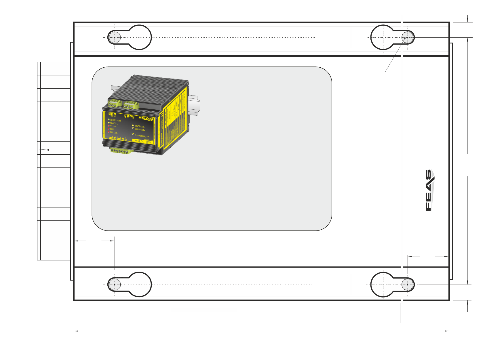
2. Montage
Das SNT230 kann mit vier M8-Schrauben an eine Wand
geschraubt werden. Hierzu bitte die Bohrschablone auf der
Seite 3 beachten. ACHTUNG! Zur besseren Wärmeabfuhr
sollte das Gerät einen Freiraum zu anderen Gegenständen
von min.15mm haben.
2. Installation
The SNT230 can be mounted on a wall with four M8-screws.
Take notice of the drill pattern attached to the package.
CAUTION! For improved heat dissipation, the device
should have a minimum free space of 15 mm.
3. LED Anzeigen
Das SNT230 ist mit einem Überwachungs-management
ausgestattet, welches mittel LED eine Reihe an Informationen
liefert. Die jeweiligen Bedeutungen entnehmen Sie bitte der
folgenden Tabelle.
3. LED Display
The SNT230 is equipped with a monitoring management,
which provides a range of information via LED-Display . For
the respective meanings, see the following table.
4. Elektrischer Anschluss
Das Gerät laut Anschluss-Schema unten anschließen. Hierbei
unbedingt die allgemeinen Sicherheitsvorschriften beachten.
Unsachgemäßer Anschluss kann zu einem Defekt des Gerätes
führen.
4. Electrical connection
Take care of a correct electrical connection. Take the wiring
diagram at the bottom of this side as help. Inappropriate
connection can lead to a defect of the device.
q Ausgang potentialfrei nach VDE 0551
q Tropentauglich - Gießharzvollverguß
q Kurzschlußfest, überlast- und leerlaufsicher
q Parallelschaltbar - Nutzen Sie bitte FEAS Redundanzmodule
q Oberwellenbegrenzung nach EN 61000-3-2
q Output separated according to VDE 0551
q Suitable for the tropics - Epoxy resin casted
q Short- circuit proof, no-load and overload safe
q Parallel connection possible - Use FEAS redundancy modules.
q PFC acc. to EN 61000-3-2
Für den ordnungsgemäßen Betrieb des Gerätes ist ein
Überspannungsschutz nach VDE0185-4 / EN62305-4,
und ein Netzfilter vorzusehen.
For proper operation of the device provide an
overvoltage protection, according VDE0185-4 /
EN62305-4, and a line filter.
PE
L3
L2
L1 +
-
Uout
+
-Verbraucher
consumer
Anschlußschema / Wiring diagram
Derating
Umgebungstemperatur - Ambient temperature
Kontaktbelastung der Relais:
- max. Schaltstrom 2,0 Amp.
- max. Schaltspannung 60V /250V
DC AC
Contact-load of the relays:
- max. switched current 2,0Amp.
- max. switched voltage 60V /250V
DC AC
!
Only charge accumulators or
rechargeable batteries!
Nur Akkus oder wieder-
aufladbare Batterien laden!
!
Auf Ladeschlußspannung der Batterie einstellen!
Adjust to maximum peak voltage of battery!
!
0,4
0,2
0
0,6
1,0
20100 30 50 70 90 10040 60 80
0,8
1,2
T / C°
Ausgangsstrom
Output current
Iout
Inenn
Bei Stromentnahme von mehr als 25A muss der Strom
gleichmäßig über alle Ausgangsklemmen verteilt werden.
If the output current exceeds 25A, the output current has
to be uniformly distributed over the whole output terminals.
!
Feineinstellung der
Ausgangsstrom-
begrenzung
Fine-adjustment of
Output current
limitation
Feineinstellung der
Ausgangsspannung
Fine-adjustment of
Output voltage
3 - Phasen Wechselstromeingang
AC Input
Gleichstromeingang
DC Input
L3 = +
L1 =
-
- 2 -
Verbraucher (z.B. Schütze, Motoren, Magnetventile,
etc.) die nicht ordnungsgemäß nach den relevanten
Richtlinien entstört sind (z.B. Varistoren, RC-Glieder,
etc), können zur Störung bzw. Zerstörung des
Netzgerätes führen.
Consumers (e.g. contactors, motors, solenoid valves
etc.) which have not been correctly interference-
suppressed in accordance to the relevant guidelines
(e.g. varistors, RC elements, etc.) may cause power
supply regulation to malfunction.
In Abhängigkeit zur
Umgebungstemperaur
und Lastentnahme sollte
gegebenenfalls Fremd-
belüftung eingesetzt werden.
Depending on the ambient
temperature and drawn load,
external ventilation should
be used.
5. Meldekontakte und Kontaktbelegung
Die Netzteile erlauben die Justage der Ausgangsspannung
mittels 0-10V-Steuerspannung, das Deaktivieren der
Ausgangsspannung und sind über integrierte Relais-Kontakte
fernüberwachbar.
5. Signal contacts and pin assignment
The power supplies allow the adjustment of output voltage with
0-10V control voltage, the deactivation of the output voltage
and remote monitoring via integrated relay contacts.
LED-Anzeigen / LED-Display
Line ok
green
Phase off
Load off
off
blue
off
Imax
Fail
off
red
off
off
red
red
Phase vorhanden
Phase OK
Ausgang ausgeschaltet
DC Output switched off
Netzspannung Aus
Line Voltage Off
Ausgangsspannung OK
Output voltage ok
Normalbetrieb
Standard operation
Phasenausfall
Phase loss
Netzspannung Ein
Line Voltage On
Fehler (Überlast bzw. Übertemperatur)
Error (Overload or Overtemperature)
Ausgangsspannung < 90%U (Stromlimitierung)
nenn
Output voltage < 90% U (current limitation)
nom
DC Ausgang Ein
DC Output On
Nach dem Einschalten der Eingangsspannung,
wird die Ausgangs- spannung verzögert
freigeschaltet.
The output voltage will be unlocked with a short
delay after applying the input voltage.
- 3 -
Relaiskontakte SNT230
1 2 3 4 5 67
U off
OUT
0-10V
Bezugspunkt für Kontakt 2 und 3 Reference for contact 2 and 3
Kontaktbelegung: Signal contacts:
1 1
2 2
3 3
4 4
5 5
66
7 7
Ausgangsspannung deaktivieren
Durch das Verbinden der Kontakte 1 und 2 wird die
Ausgangsspannung des Gerätes auf 0V reduziert.
Deactivate output voltage
Connect contact 1 with 2 to reduce the output
voltage to 0V
0-10V Schnittstelle (Details auf der nächsten Seite.) 0-10V interface (see next page for details)
Gemeinsamer Relaisanschluss
Gemeinsamer Anschluss der Relais an Kontakt 5 - 7 Common relay contact
Common relay contact for contact 5 - 7
Power Good
Fällt die Ausgangsspannung unter 90% der
Nennausgangsspannung wird ein internes Relais
geschaltet, so dass Kontakt 4 zu 6 geöffnet wird.
Power Good
An internal relay will be switched, when the output
voltage sinks below 90% of the nominal voltage.
Contact 4 to 6 opens
Übertemperatur
Bei zu hoher Gerätetemperatur wird ein internes Relais
geschaltet, so dass Kontakt 4 zu 7 geöffnet wird
Overtemperature
An internal relay will be switched, when the device
temperature is too high. Contact 4 to 7 opens.
Phasenausfall
Bei Ausfall einer Phase wird ein internes Relais
geschaltet, so dass Kontakt 4 zu 5 geschlossen wird.
Phase lost
An internal relay will be switched, when a phase is
disconnected. Contact 4 to 5 closes.
Gerät erst nach Hochlauf voll belasten! - Erkennt das Gerät beim Hochlauf eine Über-
last oder Kurzschluss, so schaltet es ab und startet erst nach ca 5 Minuten erneut.
Only load the device fully after startup! - If the device recognizes an over-Load or
short circuit, it turns off and starts again after about 5 minutes.
0
0,1
0,2
0,3
0,4
0,5
0,6
0,7
0,8
0,9
1
0 0,5 1 1,5 2 2,5 3 3,5 4 4,5 5 5,5 6 6,5 7 7,5 8 8,5 9 9,5 10
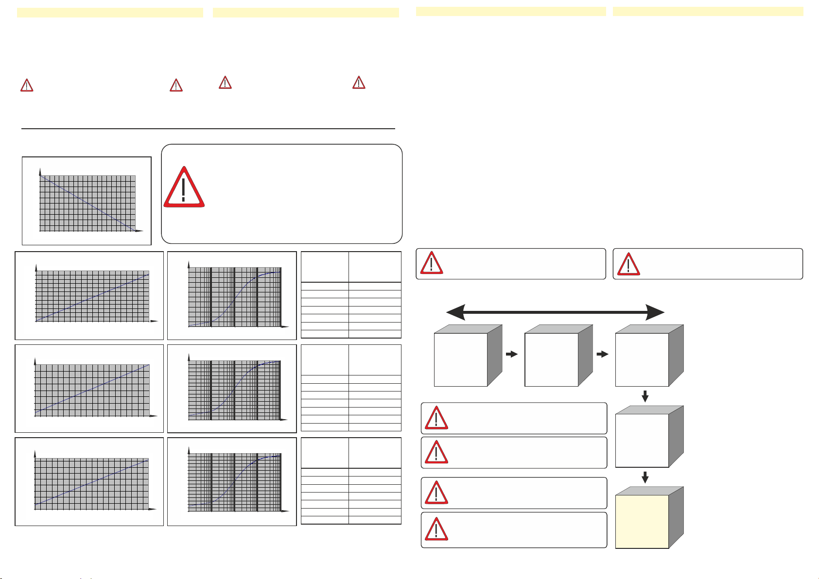
I-U-Kennlinie / Characteristic curve
SNT23012
SNT23024 - SNT23048
Ic / mA
Uc / V
Steuerspannung / Control voltage
Steuerstrom / Control current
Kennlinien / Characteristic curves
44
46
48
50
52
54
56
58
60
0 0,5 1 1,5 2 2,5 3 3,5 4 4,5 5 5,5 6 6,5 7 7,5 8 8,5 9 9,5 10
Ua-Uc-Kennlinie / Characteristic curve
SNT23048
Ua / V
Steuerspannung / Control voltage
Ausgangsspannung
Output voltage
Uc / V
Zur genaueren Bestimmung der Steuerspannung oder des Steuerwiderstandes laden sie
sich das Excel-Sheet, aus den Details des Netzteiles, auf www.feas.de herunter.
.
Please down load the Excel-Sheet from the details of the power supply, on www.feas.com,
to get the exactly control voltage or control resistor.
1k0
3k32
10k0
20k0
100k0
475k0
1M0
Steuerwiderstand
nach E96-Reihe
.
Control resistor
acc. to E96-Series
Ausgangsspannung
SNT20012
.
Output voltage
SNT20012
10,54VDC
11,42VDC
12,81VDC
13,74VDC
15,09VDC
15,49VDC
15,54VDC
1k0
3k32
10k0
20k0
100k0
475k0
1M0
Steuerwiderstand
nach E96-Reihe
.
Control resistor
acc. to E96-Series
Ausgangsspannung
SNT20024 / SNT23024
.
Output voltage
SNT20024 / SNT23024
23,18VDC
24,37VDC
26,25VDC
27,50VDC
29,32VDC
29,85VDC
29,93VDC
1k0
3k32
10k0
20k0
100k0
475k0
1M0
Steuerwiderstand
nach E96-Reihe
.
Control resistor
acc. to E96-Series
Ausgangsspannung
SNT23048
.
Output voltage
SNT23048
46,69VDC
49,08VDC
52,87VDC
55,39VDC
59,05VDC
60,11VDC
60,28VDC
Beispiele für die Ausgangsspannung
gesteuert durch einen, an der Schnitt-
stelle angeschlossenen, Widerstand.
Examples for the output voltage
controlled by a resistor, connected
to the interface.
10
10,5
11
11,5
12
12,5
13
13,5
14
14,5
15
15,5
16
0 0,5 1 1,5 2 2,5 3 3,5 4 4,5 5 5,5 6 6,5 7 7,5 8 8,5 9 9,5 10
Ua-Uc-Kennlinie / Characteristic curve
SNT23012
Ua / V
Steuerspannung / Control voltage
Ausgangsspannung
Output voltage
Uc / V
10
10,5
11
11,5
12
12,5
13
13,5
14
14,5
15
15,5
16
0,1 1 10 100 1000
Ua-Rc-Kennlinie / Characteristic curve
SNT23012
Ua / V
Rc / kW
Steuerwiderstand / Control resistor
Ausgangsspannung
Output voltage
2 3 4 20 30 40 200 3000,2 0,3
22
23
24
25
26
27
28
29
30
0 0,5 1 1,5 2 2,5 3 3,5 4 4,5 5 5,5 6 6,5 7 7,5 8 8,5 9 9,5 10
Ua-Uc-Kennlinie / Characteristic curve
SNT23024
Ua / V
Steuerspannung / Control voltage
Ausgangsspannung
Output voltage
Uc / V
22
22,5
23
23,5
24
24,5
25
25,5
26
26,5
27
27,5
28
28,5
29
29,5
30
0,1 1 10 100 1000
Ua / V
Ua-Rc-Kennlinie / Characteristic curve
SNT23024
Rc / kW
Steuerwiderstand / Control resistor
Ausgangsspannung
Output voltage
2 3 4 20 30 40 200 300
0,2 0,3
44
45
46
47
48
49
50
51
52
53
54
55
56
57
58
59
60
61
0,1 1 10 100 1000
Ua-Rc-Kennlinie / Characteristic curve
SNT23048
Ua / V
Rc / kW
Steuerwiderstand / Control resistor
Ausgangsspannung
Output voltage
2 3 4 20 30 40 200 300
0,2 0,3
0 - 10V-Schnittstelle 0 - 10V-Interface
Die Ansteuerung der Schnittstelle erfolgt über ein störungssicheres Gleichspannungssignal
von 0V (min. Ausgangsspannung 10,0V / 23,5V / 47,0V) bis
10V (max. Ausgangsspannung 15,5V / 30,0V, / 60,5V).
Aufgrund der Eigenschaften dieser Schnittstelle müssen folgende Punkte beachtet werden:
- Um die Schnittstelle zu verwenden ist das eingebaute Potentiometer “Uadj” auf die
höchste Ausgangsspannung einzustellen.
- Die Steuerleistung wird vom Netzteil selbst erzeugt (max. Strom 1mA pro Netzteil). Dies
ermöglicht eine einfache Verstellung der Ausgangsspannung mit nur einem Widerstand
an den Klemmen der Schnittstelle.
- Die Steuerleitung ist potentialgetrennt von der Eingangsspannung,
jedoch nicht von der Ausgangsspannung des Netzteils.
- Ein angeschlossenes Steuergerät muss in der Lage sein, den von den Netzteilen in die
Steuerleitung gelieferten Strom aufzunehemen (Stromsenke) und die Steuerspannung zu
verringern. Nicht alle Netzgeräte, Wandlerkarten usw. haben diese Eigenschaften!
- Die Steuerleitung muss mit richtiger Polarität (”+” = Kontakt 3 / “-” = Kontakt 1)
angeschlossen werden.
The interface will be controlled by an interference proof DC-Voltage from
0V (min. output voltage 10,0V / 23,5V / 47,0V) to 0V (max. output voltage 15,5V / 30,0V / 60,5V)
Because of the special attributes of these interface the following issues should be observed:
- To operate the interface, the integrated potentiometer “Uadj” has to be adjust to the
maximum output voltage.
- The power supply generates the control power by it is self (max. current 1mA each power
supply). This allows an adjustment of the output voltage by using a resistor connected
to the terminals of the interface.
- The control wire is potential separated from the input voltage,
but not from the output voltage.
- The connected controller has to be able to take the control current of the power supplies
(current sink) and to lower the control voltage. Please notice that not all power supplies,
transformer cards etc. have these features.
- The control wire has to be connected with the correct polarity
(”+” = contact 3 / “-” = contact 1).
9. Allgemeine Sicherheitsvorschriften
Beim Umgang mit Produkten, die mit elektrischen Spannungen in
Berührung kommen, müssen die gültigen VDE / IEC / EN Vorschriften
beachtet werden. Besonders sei auf folgende Vorschriften hingewiesen:
VDE 0100, VDE 0550 / 0551, VDE 0711, VDE 0860, IEC 664, IEC 742, IEC
570, IEC 65
Bei Nichtbeachtung der Bedienungsanleitung oder der Anschlußvorschrift,
z.B. bei Vertauschen der Anschlußklemmen, kann das Gerät oder die
Anlage beschädigt werden und der Betreiber verliert seinen möglichen
Haftungsanspruch.
Werkzeuge dürfen an Geräten, Bauteilen oder Baugruppen nur benutzt
werden, wenn sichergestellt ist, dass die Geräte von der Versorgungs-
spannung getrennt sind und interne elektrische Bauteile entladen sind.
Vor dem Öffnen des Gerätes den Netzstecker ziehen und sicherstellen,
dass das Gerät spannungslos ist und bleibt. Bauteile, Baugruppen oder
Geräte dürfen nur in Betrieb genommen werden, wenn sie vorher in ein
berührungssicheres Gehäuse eingebaut wurden. Während des Einbaus
müssen sie stromlos sein.
Spannungsführende Kabel oder Leitungen mit denen das Gerät, das Bauteil
oder die Baugruppe verbunden sind müssen stets auf Isolationsfehler oder
Bruchstellen untersucht werden. Bei Feststellen eines Fehlers in der
Zuleitung muß das Gerät unverzüglich aus dem Verkehr genommen
werden, bis die defekte Leitungen ausgewechselt worden sind.
Der Anwender hat dafür Sorge zu tragen, dass die angegebenen
Gerätedaten nicht überschritten werden.
Wenn aus den vorgelegten Beschreibungen für den Anwender oder
Erwerber nicht eindeutig hervorgeht, welche Kennwerte für ein Gerät oder
Bauteil gelten, so muss stets ein Fachmann um Auskunft ersucht werden.
Im übrigen unterliegt die Einhaltung von Bau- und Sicherheitsvorschriften
aller Art ( VDE, TÜV, Berufsgenossenschaften ) dem Anwender / Käufer.
9.General safety rules
When working with products which are in contact to dangerous electrical
voltages, attention must be payed to the relevant valid VDE / IEC / EN
regulations. Especialy with refrence to the following rules:
VDE 0100, VDE 0550 / 0551, VDE 0711, VDE 0860, IEC 664, IEC 742, IEC
570, IEC 65
In case of non-observance of this instructions the unit or other equipment
might be damaged and no warranty or liability could be accepted.
When it is necessary to use tools on the device components parts or
subassemblies make sure that the power is disconnected from the device
and all capacities are discharged.
Before opening the equipment disconnect the power cord and make sure
that the contacts are not energized. It is only allowed to take components
parts, subassemblies or device into operation if they are mounted in an
insulated housing. During the installation all devices have to be
disconnected from power sources.
Power cords and leads which are connected to the device, components or
subassemblies have to be inspected for damaged insulation. If a failure is
detected the device or the subassembly has to be put out of service at
once. It is not allowed to take the device or the subassembly into operation
before replacing the damaged power cord.
It is up to the user’s responsibility that the specification limits of the device
are not exeeded.
If the user is not fully able to relate the technical guidelines, a technical
adviser has to be asked for information.
The observance of construction requirements and safety rules (VDE, IEC,
employers liability insurenance i.e.) is subject to the user/customer.
Für den ordnungsgemäßen Betrieb des Gerätes ist ein
Überspannungsschutz nach VDE0185-4 / EN62305-4,
eine Vorsicherung, gemäß Tabelle, und ein Netzfilter
vorzusehen.
For proper operation of the device provide an
overvoltage protection, according VDE0185-4 /
EN62305-4, an input fuse as shown in table and a line
filter.
device
e.g. SNT230
Grobschutz
Surge protective
devices
Typ1
>1300V
Mittelschutz
Surge protective
devices
Typ2
>600V
Feinschutz
Surge protective
devices
Typ3
<600V
Netzfilter
linefilter
e.g.
FEAS NFK
VDE0185-4 / EN62305-4
Blitzschutz
lightning and over-
voltage protection
Transienten-
und EMV-Schutz
Transient
protection
- 5 -- 4 -
Die Einstellung der Ausgangsspannung sowie der
Stromgrenze kann nur innerhalb der nächsten
5 Minuten nach anlegen der Netzspannung erfolgen.
The setting of the output voltage as well as the
current limit can only be accomplished within the next
5 minutes after the mains voltage has been applied.
Nach Betrieb mit Überlast wird das Gerät, lastabhängig
abschalten und nach ca. 5 Minuten erneut starten.
Bei einem Kurzschluss am Ausgang erfolgt der Wieder-
start nach ca. 8 Minuten.
After operation with overload, the device will be,
dependent on the overcurrent, switch off and restart
after approx. 5 minutes.
In the event of a short circuit at the output, the restart
after about 8 minutes.
Bitte beachten!
Please note!
Bei Betrieb des Gerätes mit Gleichstrom als
Versorgungsspannung, kann die Lastentnahme
nur 50% der Lastentnahme betragen welche
bei Wechselstromeingang möglich ist.
When operating the device with DC as a supply
voltage, the load can only take 50% of the load
amount which is possible with AC input.
LDR30MH24
Mini DC-USV für die Hutschiene
Art.Nr.: 589960
Ÿ3 in 1, vereint Schaltnetzteil, Ladekontrolleinheit und Akku in
einem sehr kompakten Gehäuse
ŸPufferung eines Verbrauchers bei Netzausfall
ŸPufferzeit begrenzbar (1-20 Minuten und unbegrenzt)
ŸIm Pufferbetrieb manuell abschaltbar, “Schlafenlegen”
ŸIntegrierter NiMH Akkumulator mit 0,72 Ah (austauschbar)
ŸMikroprozessorgesteuerte Akkumulator-Überwachung und
Ladeanzeige
ŸLED-Anzeigen für Netzausfall, Überlast und Übertemperatur
ŸRelais-Meldung von Netzausfall, Übertemperatur, Akku-
Defekt und Akkuspannung kritisch
ŸBoostfunktion: 150% Iout bis zu 30s
ŸKurzschlussfest, überlast- und leerlaufsicher
ŸAusgang potentialfrei nach VDE 0551
ŸSicherheit nach VDE, EN, UL und CSA
Technische Daten:
Eingang: 85-270 VAC (0-400 Hz) / 120-380 VDC
Ausgangsspannung: 24 VDC (22,5 VDC - 29,5 VDC)
Ausgangsstrom: 2,0 A (3,0 A Boost)
Kapazität: 0,72 Ah
Leistung: 48,0 Watt
Wirkungsgrad: ca. 91%
Restwelligkeit: < 50 mVSS
Arbeitstemperatur: -20°C / +70°C
Montage: auf Hutschiene nach DIN 46277
Abmaße (BxHxT): 108,0 x 100,0 x 120,0 mm
Gewicht: 2,30 kg
230 mm
151,5
9,5 9,5
25,0
25,0
GmbH
Postfach 1521
D - 22905 AHRENSBURG
Telefon: 04102 - 42082
Telefax: 04102 - 40930
www.feas.de
© 2017 ®
Klemmen / terminals
Maße Rückseite - Dimensions backside
Geeignet für M8 Schrauben
Suitable for M8 screws
This manual suits for next models
3
Other FEAS Power Supply manuals


