Ethernet-I/P Fieldbus Expansion Unit
PAGE 8
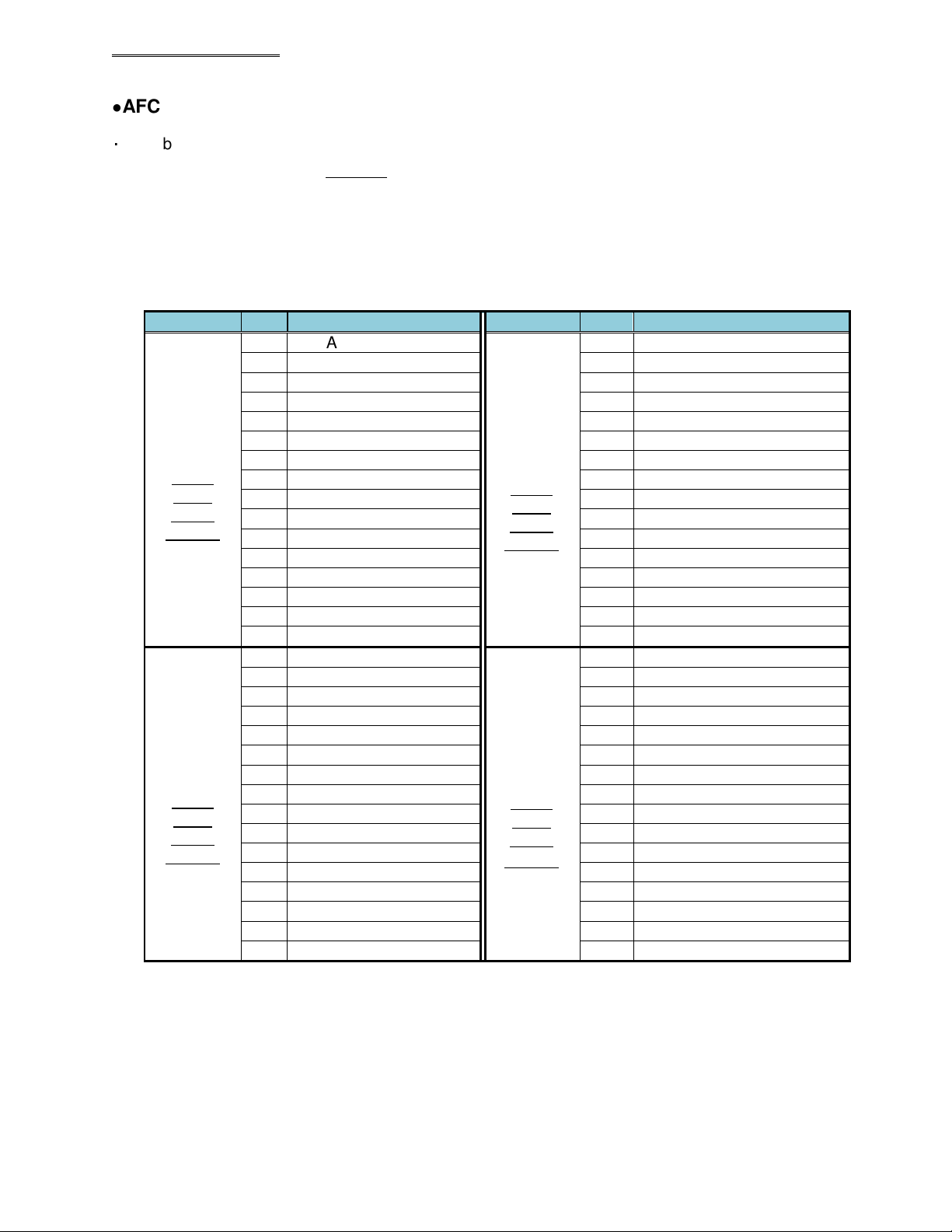
No.05
No.06
11
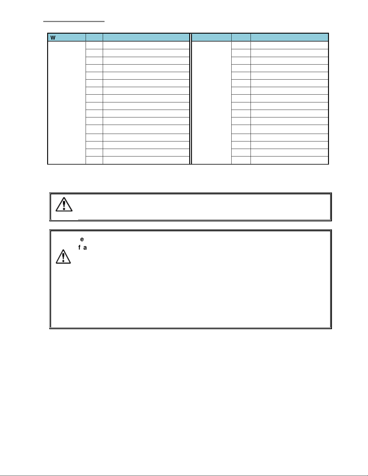
BYPASS SPDL No.22 11
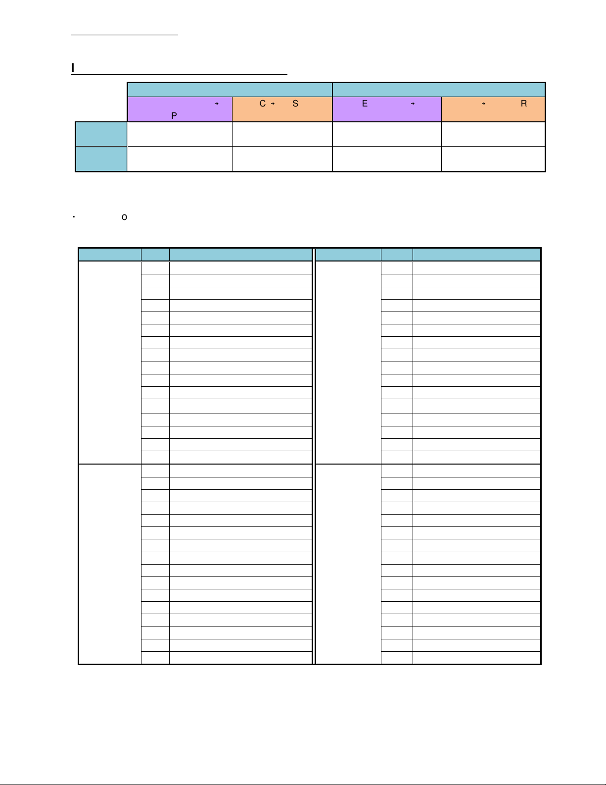
* The word No. at the PLC side differs according to the setting of the node address, etc., so please be sure
to confirm before using. Please refer to the AFC3000 Operation Manual, Section 5-3-2 and 5-3-3 for
description of the respective signals.
The allocation of the input signals is fixed (cannot be changed).
The unused area of the inputs is also secured
(and cannot be used by other
devices).
Be careful of the following points when using the BYPASS No. # (1 to 32) signals.
If a certain Unit is to be put in the BYP
ASS mode, set the corresponding signal
among the BYPASS No. # (1 to 32) signals to “ON” with the START signal of the Unit
being in the “OFF” state and the BUSY signal of the MASTER Spindle
communication and I/O (PLC) control being in the “OFF” state.
When fastening is executed with any of the spindle
BYPASS No. # (1 to 32) signals
in the “ON” state, the fastening judgment of th
at Unit will be ignored as if it does not
exist.
Also, when any of the BYPASS No. # (1 to 32) signals is set to “ON” with th
of the MASTER Spindle
being in the “ON” state, the sequence judgment may result
in REJECT.
Caution
Cautio