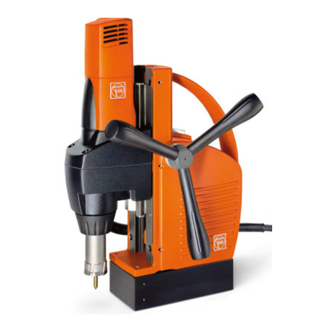
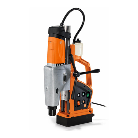
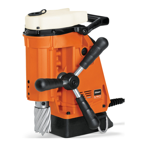
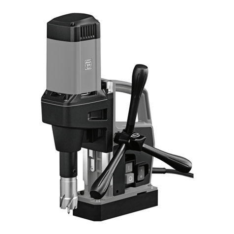
Fein KBU 35 PQ Setup guide

Metal core drilling
Repair instructions
Applies to:
KBU 35 PQ; KBU 35 PQW; JMU 137 PQW

Metal core drilling
Contents
C-SC_CSSM
Version 1.0
11.02.2019
Page 2of 88
All rights reserved by FEIN, especially in case of property rights applications.
FEIN retains all rights of disposal, such as copying and circulation.
Contents
1Models described..............................................................................................................................5
2Technical data...................................................................................................................................6
3Symbols used....................................................................................................................................7
4Notes and requirements....................................................................................................................8
5Safety instructions.............................................................................................................................9
6Tools, lubricants and auxiliary substances required.........................................................................11
6.1 Standard tools..........................................................................................................................11
6.2 Special tools.............................................................................................................................12
6.3 Lubricants and auxiliary substances required...........................................................................12
7Test and diagnostics options...........................................................................................................13
8Removal..........................................................................................................................................14
8.1 Removing the carbon brushes..................................................................................................14
8.2 Disassembling the drill jig.........................................................................................................15
8.2.1 Removing the container ....................................................................................................15
8.2.2 Removing the electronics..................................................................................................16
8.2.3 Removing the drill motor ...................................................................................................17
8.2.4 Removing the magnetic foot..............................................................................................19
8.2.5 Removing the magnetic foot..............................................................................................20
8.2.6 Removing the sealing ring.................................................................................................22
8.2.7 Removing the guide ..........................................................................................................23
8.2.8 Removing the spider .........................................................................................................26
8.2.9 Removing the spider .........................................................................................................27
8.3 Removing the network cable ....................................................................................................28
8.4Removing the motor housing....................................................................................................29
8.4.1 Removing the control panel...............................................................................................29
8.4.2 Removing the gearbox housing.........................................................................................31
8.4.3 Removing the intermediate gearbox..................................................................................32
8.4.4 Removing the housing.......................................................................................................33
8.4.5 Removing the connecting piece ........................................................................................34
8.4.6 Removing the stator..........................................................................................................35
8.4.7 Removing the drill motor electronics..................................................................................36
8.4.8 Removing the armature.....................................................................................................37
8.5 Removing the gearbox housing................................................................................................39

Metal core drilling
Contents
C-SC_CSSM
Version 1.0
11.02.2019
Page 3of 88
All rights reserved by FEIN, especially in case of property rights applications.
FEIN retains all rights of disposal, such as copying and circulation.
8.5.1 Removing the holder.........................................................................................................39
8.5.2 Removing the gearbox parts .............................................................................................43
8.5.3 Removing the gear-wheels................................................................................................45
8.5.4 Removing the shaft ...........................................................................................................46
8.5.5 Removing the shaft ...........................................................................................................47
9Fitting..............................................................................................................................................48
9.1 Fitting the gearbox housing......................................................................................................48
9.1.1 Fitting the shaft..................................................................................................................48
9.1.2 Positioning the shaft..........................................................................................................49
9.1.3 Fitting the gear-wheels......................................................................................................51
9.1.4 Fitting the gearbox parts....................................................................................................52
9.1.5 Fitting the holder ...............................................................................................................54
9.2 Fitting the motor housing..........................................................................................................58
9.2.1 Fitting the armature...........................................................................................................58
9.2.2 Fitting the drill motor electronics........................................................................................61
9.2.3 Fitting the stator ................................................................................................................62
9.2.4 Fitting the connecting piece...............................................................................................63
9.2.5 Fitting the housing.............................................................................................................64
9.2.6 Fitting the intermediate gearbox........................................................................................65
9.2.7 Fitting the gearbox housing...............................................................................................66
9.2.8 Fitting the control panel.....................................................................................................67
9.3 Assembling the drill jig..............................................................................................................69
9.3.1 Fitting the spider................................................................................................................69
9.3.2 Positioning the spider........................................................................................................70
9.3.3 Fitting the guide.................................................................................................................71
9.3.4 Fitting the sealing ring.......................................................................................................74
9.3.5 Fitting the magnetic foot....................................................................................................75
9.3.6 Positioning the magnetic foot ............................................................................................78
9.3.7 Fitting the drill motor..........................................................................................................79
9.3.8 Fitting the electronics ........................................................................................................81
9.3.9 Fitting the container...........................................................................................................82
9.4 Fitting the network cable...........................................................................................................83
9.5 Fitting the carbon brushes........................................................................................................84
9.6 Setting the guide......................................................................................................................85

Metal core drilling
Contents
C-SC_CSSM
Version 1.0
11.02.2019
Page 4of 88
All rights reserved by FEIN, especially in case of property rights applications.
FEIN retains all rights of disposal, such as copying and circulation.
10 Inspection following repairs .............................................................................................................88

Metal core drilling
Models described
C-SC_CSSM
Version 1.0
11.02.2019
Page 5of 88
All rights reserved by FEIN, especially in case of property rights applications.
FEIN retains all rights of disposal, such as copying and circulation.
1 Models described
These repair instructions describe how to repair the following models:
Model
Material number
KBU 35 PQ
7 270 71 .. .. .
KBU 35 PQW
7 270 72 .. .. .
JMU 137 PQW
7 270 73 .. .. .

Metal core drilling
Technical data
C-SC_CSSM
Version 1.0
11.02.2019
Page 6of 88
All rights reserved by FEIN, especially in case of property rights applications.
FEIN retains all rights of disposal, such as copying and circulation.
2 Technical data
Technical data
The complete technical data can be found in the operating instructions for the model.
Troubleshooting
Troubleshooting for all devices can be found in the FEIN electronic information system.
Specific test specifications and measured values
Up-to-date test data for all devices can be found in the FEIN electronic information system.
Special tools, lubricants and auxiliary substances
The special tools catalogue and the lubricants and container sizes available from FEIN can be found in the
FEIN electronic information system.
Lists of spare parts
Lists of spare parts and exploded views are available online in our spare parts catalogue, which can be
accessed via the FEIN website.
Connection diagram
Lists of spare parts and exploded views can be found in the FEIN electronic information system.

Metal core drilling
Symbols used
C-SC_CSSM
Version 1.0
11.02.2019
Page 7of 88
All rights reserved by FEIN, especially in case of property rights applications.
FEIN retains all rights of disposal, such as copying and circulation.
3 Symbols used
Refers to measures for avoiding the risk of injuries.
Caution: Crushing hazard
Refers to information or instructions that should be followed. Non-observance can result in
damage or malfunctions.
Read the operating instructions.
Indicates notes that provide information or instructions that may provide a better understanding
and contribute to the more effective use of the product.
Part of the navigation interface.

Metal core drilling
Notes and requirements
C-SC_CSSM
Version 1.0
11.02.2019
Page 8of 88
All rights reserved by FEIN, especially in case of property rights applications.
FEIN retains all rights of disposal, such as copying and circulation.
4 Notes and requirements
Please note
These instructions are only intended for persons with suitable technical training. It is assumed that the
reader has mechanical and electrical training.
Only use original FEIN spare parts.
Provisions
Please note that power tools may only be repaired, maintained and checked by a trained electrician, as
improper repair can result in serious risks to the user.
Outside Germany, the regulations applicable in the relevant country must be observed.
The provisions set out in DIN VDE 0701-0702 should be observed after repairs.
The relevant accident prevention regulations are to be observed during commissioning.
The German Equipment and Product Safety Act [ProdSG] applies for correct use.
Disclaimer
The content of this documentation has been carefully reviewed and produced to the best of our knowledge.
C. & E. Fein GmbH assumes no responsibility for the completeness, relevance, quality or correctness of the
information provided.
Liability claims against C. & E. Fein GmbH that relate to material or immaterial damage caused by the use
or failure to use the information provided or by the use of incorrect or incomplete information are excluded.
Claims relating to acts committed intentionally or through gross negligence are categorically excluded.
INFORMATION
Read the operating instructions for the product before
carrying out the repair work.

Metal core drilling
Safety instructions
C-SC_CSSM
Version 1.0
11.02.2019
Page 9of 88
All rights reserved by FEIN, especially in case of property rights applications.
FEIN retains all rights of disposal, such as copying and circulation.
5 Safety instructions
5.1 Structure
5.2 Danger classification
Warning
This warning refers to a dangerous situation. If the situation is not avoided, this may result in severe injuries
or death.
Caution
This warning refers to a potentially dangerous situation. If the situation is not avoided, this may result in
slight or minor injuries. This may also be used as a warning against material damage.
Please note
Indicates a potentially harmful situation. If this situation is not avoided, the product or an object in its
environment could be damaged.
SIGNAL WORD FOR THE DANGER
CLASSIFICATION.
Type and source of the danger.
Possible consequences.
Measure that must be taken in order to avoid this danger.
WARNING!
Type and source of the danger.
Possible consequences.
Measure that must be taken in order to avoid this danger.
CAUTION!
Type and source of the danger.
Possible consequences.
Measure that must be taken in order to avoid this danger.
PLEASE NOTE!
Type and source of the danger.
Damage to the product or its environment.
Measure that must be taken in order to avoid this danger.

Metal core drilling
Safety instructions
C-SC_CSSM
Version 1.0
11.02.2019
Page 10 of 88
All rights reserved by FEIN, especially in case of property rights applications.
FEIN retains all rights of disposal, such as copying and circulation.
5.3 Information
Indicates notes that provide information or instructions that may provide a better understanding and
contribute to the more effective use of the product.
INFORMATION
Tip

Metal core drilling
Tools, lubricants and auxiliary substances required
C-SC_CSSM
Version 1.0
11.02.2019
Page 11 of 88
All rights reserved by FEIN, especially in case of property rights applications.
FEIN retains all rights of disposal, such as copying and circulation.
6 Tools, lubricants and auxiliary substances required
6.1 Standard tools
Cross-tip screwdriver
PH2
Torx
T20
Slotted screwdriver
125x7
Socket head wrench set
Circlip pliers
Plastic hammer
Arbor press
Long-nosed pliers
Combination pliers
Socket wrench
7 mm
Sleeve
5 mm inner diameter
16 mm outer diameter;
13 mm inner diameter
26 mm outer diameter;
7 mm inner diameter
18 mm outer diameter;
7 mm inner diameter
13 mm outer diameter;
10 mm inner diameter
23 mm outer diameter;
26 mm inner diameter
30 mm outer diameter;
17 mm inner diameter
25 mm outer diameter;
5 mm inner diameter
15 mm outer diameter;
16 mm inner diameter
25 mm outer diameter;
10 mm inner diameter
24 mm outer diameter;
26 mm inner diameter
42 mm outer diameter
Torque wrench with hexagon socket
fixture
2.5 mm

Metal core drilling
Tools, lubricants and auxiliary substances required
C-SC_CSSM
Version 1.0
11.02.2019
Page 12 of 88
All rights reserved by FEIN, especially in case of property rights applications.
FEIN retains all rights of disposal, such as copying and circulation.
6.2 Special tools
Assembly aid
6 41 22 121 01 0
Drawing-off socket cap
6 41 04 150 00 0
Chuck cone
19 mm
diameter
26 mm
diameter
6 41 07 019 00 7
6 41 07 026 00 0
6.3 Lubricants and auxiliary substances required
Grease
0 401 18 0300 9
45 g
Gearbox

Metal core drilling
Test and diagnostics options
C-SC_CSSM
Version 1.0
11.02.2019
Page 13 of 88
All rights reserved by FEIN, especially in case of property rights applications.
FEIN retains all rights of disposal, such as copying and circulation.
7 Test and diagnostics options
Not currently available.

Metal core drilling
Removal
C-SC_CSSM
Version 1.0
11.02.2019
Page 14 of 88
All rights reserved by FEIN, especially in case of property rights applications.
FEIN retains all rights of disposal, such as copying and circulation.
8 Removal
8.1 Removing the carbon brushes
Tools:
- Torx T15
- Assembly aid
1. Unscrew the screw (1).
2. Remove the cover (2).
3. Lift up the spring (3).
4. Pull off the two plugs (4).
5. Remove the carbon brush (5).
6. Repeat steps 1 to 5 on the opposite side of the machine.
1
2
3
4
5

Metal core drilling
Removal
C-SC_CSSM
Version 1.0
11.02.2019
Page 15 of 88
All rights reserved by FEIN, especially in case of property rights applications.
FEIN retains all rights of disposal, such as copying and circulation.
8.2 Disassembling the drill jig
8.2.1 Removing the container
1. Remove the container (1).
2. Remove the hose (2) from the hose socket.
INFORMATION
Tip
Fluid may be present in the container.
- Always drain the container (1) before disassembly.
2
1
Photo shows similar
product

Metal core drilling
Removal
C-SC_CSSM
Version 1.0
11.02.2019
Page 16 of 88
All rights reserved by FEIN, especially in case of property rights applications.
FEIN retains all rights of disposal, such as copying and circulation.
8.2.2 Removing the electronics
Tools:
- Torx T20; T15
1. Unscrew the four screws (1).
2. Remove the cover (2).
3. Unscrew the two screws (3).
4. Remove all of the cables.
5. Open the four retaining brackets (4).
6. Remove the protective hose (5).
7. Unscrew the three screws (6).
8. Remove the electronics (7).
9. Remove the plug (8).
1
2
4
5
Photo shows similar
product
3
6
7
8

Metal core drilling
Removal
C-SC_CSSM
Version 1.0
11.02.2019
Page 17 of 88
All rights reserved by FEIN, especially in case of property rights applications.
FEIN retains all rights of disposal, such as copying and circulation.
8.2.3 Removing the drill motor
Steps that must be completed:
- Removing the electronics
Tools:
- PH2 cross-tip screwdriver
1. Unscrew the fillister head screw (1).
2. Remove the protective hose (2).
3. Unscrew the two levers (3).
CAUTION!
Crushing hazard around the drill motor
Crushing can occur.
Move the drill motor down using the spider, before the two
levers (3) are unscrewed.
1
3
2
Photo shows similar
product
Photo shows similar
product

Metal core drilling
Removal
C-SC_CSSM
Version 1.0
11.02.2019
Page 18 of 88
All rights reserved by FEIN, especially in case of property rights applications.
FEIN retains all rights of disposal, such as copying and circulation.
8.2.3 Removing the drill motor
4. Lift the drill motor (1) out of the guide.
5. Remove the pressure piece (2).
2
1
Photo shows similar
product

Metal core drilling
Removal
C-SC_CSSM
Version 1.0
11.02.2019
Page 19 of 88
All rights reserved by FEIN, especially in case of property rights applications.
FEIN retains all rights of disposal, such as copying and circulation.
8.2.4 Removing the magnetic foot
Steps that must be completed:
- Removing the electronics
Tools:
- Socket head wrench, 5 mm
1. Unscrew the four screws (1).
2. Remove the magnetic foot (2).
1
2

Metal core drilling
Removal
C-SC_CSSM
Version 1.0
11.02.2019
Page 20 of 88
All rights reserved by FEIN, especially in case of property rights applications.
FEIN retains all rights of disposal, such as copying and circulation.
8.2.5 Removing the magnetic foot
Steps that must be completed:
- Removing the electronics
- Removing the magnetic foot
Tools:
- Torx T10
- Socket head wrench, 3 mm; 5 mm
- Assembly aid
-M5x30 screw
-M5 nut
1. Unscrew the two screws (1).
2. Remove the switch (2).
3. Remove the sensor (3).
4. Remove the hose (4).
1
2
3
4
Photo shows similar
product
This manual suits for next models
2
Table of contents
Other Fein Drill manuals

Fein
Fein ASz648a Installation and operation manual

Fein
Fein DS 648 Quick start guide

Fein
Fein HandyMaster ABS 12V Quick start guide

Fein
Fein DSc 636 User manual

Fein
Fein BOZ 32-4M User manual

Fein
Fein KBM 32Q User manual

Fein
Fein HandyMaster ASB 14V User manual

Fein
Fein KBB40X User manual

Fein
Fein MBS16X User manual

Fein
Fein ASzxeu 636-1 Kinetik User manual