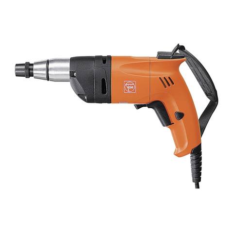
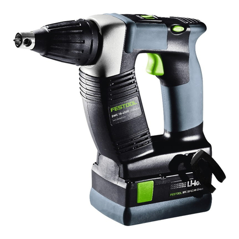
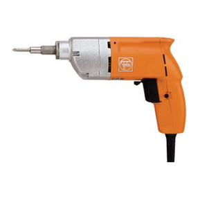
Fein SCT 5-40 U User manual

SCT 5-40 SCT 5-40 U
SCT 6-25
7 213 01 7 213 02
7 213 03
3 41 01 033 06 8
Printed in Germany 09.03
3 41 01 033 06 8 - Buch Seite 1 Donnerstag, 4. September 2003 3:43 15

2
Deutsch
English
Français
Italian
Nederlands
Españ l
P rtuguês
EÏÏËÓÈο
Dansk
N rsk
Svenska
Su mi
Magyar
âesky
Slovensky
Polski
На русском
языке
5
10
15
20
25
30
35
40
45
50
55
60
65
70
75
80
92
98
85
3 41 01 033 06 8 - Buch Seite 2 Donnerstag, 4. September 2003 3:43 15

3
5
a
b
4
12
SCT 5-40 U
SCT 6-25
SCT 5-40 U
3
6d
c
e
f
g
3 41 01 033 06 8 - Buch Seite 3 Donnerstag, 4. September 2003 3:43 15

4
70
08
B
A
9
B-A
10
B-A-C
C
h
i
3 41 01 033 06 8 - Buch Seite 4 Donnerstag, 4. September 2003 3:43 15

SCT 5-40 / SCT 5-40 U / SCT 6-25
5
DE
Bedienungsanleitung Schrauber.
Auf einen Blick.
1 Tiefenanschlag
Schrau tiefe einstellen.
2 Drehm ment-Einstellschraube
(SCT 5-40 U)
Einstellung Drehmoment.
3 Handschlaufe
Gerät sicher halten, Hand entlasten.
4 Umschaltung Rechtslauf der Linkslauf
Im Stillstand umschalten.
5 Schalter
Ein- und Ausschalten (a),
Arretierung für Dauerlauf ( ).
6 Mitgeliefertes Zubehör
Einsatz 1/4" für Kreuzschlitzschrau-
en Phillips Form H Größe 2 mit
Stau schutzring (c),
Magnet ithalter (d),
Stiftschlüssel (e) (SCT 5-40 U),
Tiefenanschlag (f),
Einsatz 1/4" für Kreuzschlitzschrau-
en Pozidriv Form Z
Größe 2 (g) (SCT 6-25).
Zu Ihrer Sicherheit.
Vor Ge rauch dieses Gerätes lesen
und danach handeln:
diese Bedienungsanleitung,
die eiliegenden Sicherheitshinweise
(Schriftennummer 3 41 30 054 06 1),
die einschlägigen nationalen Ar eits-
schutz estimmungen.
Diese Bedienungsanleitung und die eilie-
genden Sicherheitshinweise sind zum spä-
teren Ge rauch aufzu ewahren und ei
einer Weiterga e oder Veräußerung dem
Gerät eizulegen.
Bestimmungsgemäße Verwendung.
Dieses Gerät ist estimmt:
für den gewer lichen Einsatz in Industrie
und Handwerk,
zum Ein- und Ausdrehen von Schrau en,
speziell für den Einsatz im Trocken au mit
Schnell auschrau en, Sel st ohrschrau-
en und Holzschrau en,
zum Einsatz mit Zu ehör, das in dieser
Bedienungsanleitung angege en ist oder
das von FEIN empfohlen wird.
SCT 5-40/SCT 6-25: Die Verschrau un-
gen sind mit Tiefenanschlag auszuführen.
Sicherheitshinweise.
Verletzungsgefahr
Gerät gut festhalten.
Nur mit un eschädigtem Einsatz ar eiten.
Vorsicht vor verdeckt liegenden elektri-
schen Leitungen, Gas- und Wasserrohren:
Den Ar eits ereich z. B. mit einem
Metallortungsgerät kontrollieren.
Keine Schilder und Zeichen auf das Gerät
nieten oder schrau en. Die Schutzisolie-
rung kann dadurch unwirksam werden.
Empfohlen werden Kle eschilder.
Nur un eschädigte Stecker und Ka el
verwenden.
Sachbeschädigung
Netzspannung und Spannungsanga e am
Gerät müssen ü ereinstimmen.
Persönliche Schutzausrüstung.
Beim Ar eiten mit diesem Gerät folgende
Schutzausrüstung tragen:
festes Schuhwerk, Haarnetz ( ei langen
Haaren).
!
!
3 41 01 033 06 8 - Buch Seite 5 Donnerstag, 4. September 2003 3:43 15

6
SCT 5-40 / SCT 5-40 U / SCT 6-25
DE
Bedienen.
Ein- und Ausschalten (5).
■Zuerst Ka el und Stecker auf Beschädi-
gungen prüfen.
Einschalten:
■Schalter (a) drücken. Drehzahl je nach
Eindrücktiefe des Schalters.
Ausschalten:
■Zum Ausschalten Schalter loslassen.
Arretieren für Dauerlauf:
■Bei ganz gedrücktem Schalter (a)
(= maximale Drehzahl) Arretier-
knopf ( ) drücken.
■Zum Entriegeln Schalter (a) nochmals
drücken und loslassen.
Drehrichtung wählen (4).
■Drehrichtung an Schalter auf Rechtslauf
oder Linkslauf stellen.
Betätigung nur im Stillstand des M t rs.
Einsatz wechseln (1).
Verletzungsgefahr
durch unbeabsichtigtes Einschalten.
Vor dem Wechseln Stecker ziehen.
■Tiefenanschlag (1) a ziehen.
■Einsatz entnehmen.
■Neuen Einsatz einrasten.
■Tiefenanschlag (1) mit Dreh ewegung
aufsetzen.
Drehm ment einstellen (2)
(SCT 5-40 U).
Verletzungsgefahr
durch unbeabsichtigtes Einschalten.
Vor dem Einstellen Stecker ziehen.
Das Gerät ist mit einer Einfach-Klauen-
kupplung ausgerüstet. Das Drehmoment
kann durch das Verstellen der Eingrifftiefe
der Kupplungsklaue verändert werden.
Großer Klaueneingriff ergi t großes
Drehmoment und kleiner Klaueneingriff
ergi t kleines Drehmoment.
Eingestellt wird durch Drehen der Dreh-
moment-Einstellschrau e (2).
■Lagerhülse a schrau en und Gewin-
destift entfernen.
■Drehmoment-Einstellschrau e (2) in
gewünschte Richtung drehen.
Rechtsdrehen der Schrau e in die fol-
gende Ker e erhöht den Eingriff um
0,16 mm. Die Eingrifftiefe ist vom Werk
auf ca. 0,75 mm eingestellt.
■Lagerhülse aufschrau en (10– 12 Nm).
Das Drehmoment ist a hängig von der
Kraft, mit der die Maschine gegen die
Schrau e gedrückt wird.
Tiefenanschlag einstellen (7 –10).
Verletzungsgefahr
durch unbeabsichtigtes Einschalten.
Vor dem Einstellen Stecker ziehen.
Der Tiefenanschlag esteht aus Ü erwurf-
hülse (i) und Anschlaghülse (h). Eine ganze
Umdrehung der Anschlaghülse (viermali-
ges Ratschen) verändert die Schrau tiefe
um 1 mm.
■Tiefenanschlag (1) mit Dreh ewegung
aufsetzen.
■Als Voreinstellung die Anschlaghülse so
einstellen, dass sie mit der Auflage-
fläche der Schrau e eine E ene ildet.
!
!
!
3 41 01 033 06 8 - Buch Seite 6 Donnerstag, 4. September 2003 3:43 15

SCT 5-40 / SCT 5-40 U / SCT 6-25
7
DE
■Eine Schrau e zur Pro e is zum
Anschlag eindrehen.
■Schrau tiefe korrigieren.
Soll die Schrau e tiefer eingedreht
werden, die Anschlaghülse hineindre-
hen. Ist die Schrau e zu tief eingedreht,
die Anschlaghülse herausdrehen.
Beispiel: Schrau e steht nach erster Ver-
schrau ung noch 1,5 mm aus dem Mate-
rial heraus. Anschlaghülse um
1,5 Umdrehungen hineindrehen, um kor-
rekte Einschrau tiefe zu erreichen.
Reinigen und Pflegen.
Verletzungsgefahr
durch unbeabsichtigtes Einschalten.
Vor Pflegearbeiten Stecker ziehen.
Einmal pro Woche, ei häufigem
Ge rauch öfter, durchführen:
■Kühlluftöffnungen reinigen.
■Motorraum von außen mit trockener
Druckluft aus lasen.
Warten und Reparieren.
Verletzungsgefahr
Warten, prüfen und reparieren dürfen nur
Elektrofachkräfte nach den im je eiligen
Land gültigen Vorschriften.
Zum Warten und Reparieren.
Wir empfehlen unsere Kundendiensta -
teilung (Zentralreparatur), FEIN-Vertrags-
werkstätten und -Vertretungen. Adressen
am Ende dieser Bedienungsanleitung und
in den eiliegenden Sicherheitshinweisen.
Diese Bedienungsanleitung der Reparatur-
werkstatt mitge en. Ersatzteilü ersicht
am Ende dieser Bedienungsanleitung.
Elektrofachkräften senden wir auf Anfor-
derung eine Reparaturanleitung zu.
Nur Original-FEIN-Ersatzteile verwen-
den.
Ersatzteile.
Ersatzteilü ersicht am Ende dieser
Bedienungsanleitung. Teile-Nr. (1),
Bestellnummer (2) sowie Anzahl der
Ersatzteile (3) erleichtern das Bestellen.
Zubehör.
Bildliche Darstellung und Bestellnummern
am Ende dieser Anleitung.
Erläuterungen zum Zu ehör:
A Tiefenanschlag, zusammengesetzt aus
Ü erwurfhülse und Anschlaghülse.
B Verschiedene Einsätze,
Schaft 1/4" Sechskant
(PZ = Pozidriv, PH = Phillips,
TX = Torx, SW = Schlüsselweite
Sechskant).
C Bit-Box
estehend aus: 1 Halter mit Federring,
magnetisch und 9 verschiedenen
Bits 1/4" für Kreuzschlitz- und Schlitz-
schrau en.
D Diamant-Bit-Box
estehend aus: 1 Halter mit Federring,
magnetisch und 6 diamant eschichtete
Bits 1/4" für Kreuzschlitzschrau en.
E Tek Bit-Box
34-teilig, estehend aus: 1 Halter mit
Federring, magnetisch, 20 Bits für
Kreuzschlitzschrau en Gr. 1 – 3
Form H/Form Z, 10 Bits für Innen-
Torx-Schrau en TX 10, 15, 20, 25,
30, 40, sowie 3 magnetische Sechs-
kant-Steckschlüsselsätze SW 8, 10,
3/8".
F Werkzeugkoffer, Metall
(390 x 240 x 110 mm).
G Werkzeugkoffer, Kunststoff
(305 x 265 x 90 mm).
!
!
3 41 01 033 06 8 - Buch Seite 7 Donnerstag, 4. September 2003 3:43 15

8
SCT 5-40 / SCT 5-40 U / SCT 6-25
DE
Garantie.
Jedes FEIN-Elektrowerkzeug wird sorgfäl-
tig geprüft und unterliegt den strengen
Maßstä en der FEIN-Qualitätssicherung.
Ü er die gesetzlichen Gewährleistungs-
pflichten hinaus leisten wir Garantie ent-
sprechend der FEIN Hersteller-
Garantieerklärung. Details darü er erfah-
ren Sie ei Ihrem Fachhändler, der FEIN-
Vertretung im Land oder eim FEIN-Kun-
dendienst.
Schäden, die durch unsachgemäße
Behandlung, Ü erlastung oder ge rauchs-
edingten Verschleiß entstanden sind,
sind generell ausgeschlossen.
Umweltschutz.
Verpackungen, ausgediente Geräte und
Zu ehör einer umweltgerechten Wieder-
verwertung zuführen.
Weitere Informationen erhalten Sie ei
Ihrem Fachhändler.
Technische Daten.
Der A- ewertete Schalldruckpegel des
Gerätes eträgt typischerweise 82 dB (A).
Der Geräuschpegel eim Ar eiten kann
85 dB (A) ü erschreiten.
Gehörschutz tragen!
Die Hand-Arm-Vi ration ist typischer-
weise niedriger als 2,5 m/s2.
Messwerte ermittelt nach EN 50 144.
Bestellnummer 7 213 01 7 213 02 7 213 03
Bauart SCT 5-40 SCT 5-40 U SCT 6-25
Nennaufnahme 450 W
Leistungsa ga e 250 W
Stromart 1 ~
Lastdrehzahl 0 –2700/min 0 –2700/min 0 –2000/min
Leerlaufdrehzahl 0 –4000/min 0 –4000/min 0 –2500/min
max. Anziehdrehmoment ei
hartem Schrau fall 12 Nm 12 Nm 16 Nm
Gewicht 1,3 kg
Schutzklasse II
Werkzeugaufnahme 1/4" Innensechskant DIN 3126 E 6.3
Schrau en-Ø 3 –5 mm 3 –5 mm 3 –6 mm
3 41 01 033 06 8 - Buch Seite 8 Donnerstag, 4. September 2003 3:43 15

SCT 5-40 / SCT 5-40 U / SCT 6-25
9
DE
CE-K nf rmität.
Wir erklären in alleiniger Verantwortung,
dass dieses Produkt mit den folgenden
Normen oder normativen Dokumenten
ü ereinstimmt: EN 50 144, EN 55 014,
EN 61 000-3-2/-3-3 gemäß den Bestim-
mungen der Richtlinien 98/37/EG und
89/336/EWG.
C. & E. FEIN Gm H & Co. KG,
Postfach 10 14 44 • 70013 Stuttgart
Bei Veränderung des Gerätes verliert
diese Erklärung ihre Gültigkeit und die
Garantie erlischt.
Bender Moini
3 41 01 033 06 8 - Buch Seite 9 Donnerstag, 4. September 2003 3:43 15
10
SCT 5-40 / SCT 5-40 U / SCT 6-25
EN
Operating instructi ns f r screwdriver.
Overview.
1 St p
Setting the screwing depth.
2 T rque adjusting key (SCT 5-40 U)
For setting the torque.
3 Hand strap
For holding the device firmly and less-
ening the strain on the hand.
4 Select r switch f r cl ckwise and
anti-cl ckwise r tati n
Select when power tool is at a stand-
still.
5 Switch
For switching ON/OFF (a),
Locking for continuous mode ( ).
6 Supplied access ries
Bit 1/4" for Phillips screws size 2,
Form H with dust protection ring (c),
Magnetic holder (d) for its,
Wrench (e) (SCT 5-40 U),
Bit stop (f),
Bit 1/4" for Pozidriv screws size 2 (g),
Form Z (SCT 6-25).
F r y ur safety.
Before using this power tool, read
and comply with:
these operating instructions,
the enclosed safety instructions
(document num er 3 41 30 054 06 1),
the relevant national industrial safety
regulations.
These operating instructions and the
enclosed safety instructions should e
kept carefully for later use and enclosed
with the power tool, should it e passed
on or sold.
Intended use.
This power tool is intended for:
commercial use in industry and trade,
for driving and removing screws, espe-
cially for use in drywall construction using
fast feed screws, self-drilling screws and
wooden screws,
for applications using the accessories given
in these operating instructions, or those
recommended y FEIN.
SCT 5-40/SCT 6-25: Screwing should e
carried out using the it stop.
Safety instructi ns.
Risk f injury
Hold the power tool firmly.
Only work with undamaged insert.
Beware of any concealed electric ca les,
gas or water conduits; check the working
area with a metal detector, for example.
Do not rivet or screw any name-plates or
signs onto the power tool. The protective
insulation can there y e rendered inef-
fective. Adhesive la els are recom-
mended.
Only use an undamaged plug and ca le.
Damage t pr perty/material
The mains voltage must correspond with
the voltage specifications on the power
tool.
Pers nal pr tective equipment.
When using this power tool wear the fol-
lowing protective items:
sturdy shoes, hair net (for long hair).
!
!
3 41 01 033 06 8 - Buch Seite 10 Donnerstag, 4. September 2003 3:43 15

SCT 5-40 / SCT 5-40 U / SCT 6-25
11
EN
Handling.
Switching ON/OFF (5).
■First check that the ca le and plug are
not damaged.
Switching the power tool ON:
■Press switch (a). The speed depends on
how far the switch is pressed in.
Switching the power tool OFF:
■To turn off, let go of switch.
Locking for continuous mode:
■When the switch (a) is fully pressed in
(= maximum speed) press the locking
utton ( ).
■To release, press switch (a) again and
then let go.
Selecting the directi n f
r tati n (4).
■Set the direction of rotation using
selector switch for clockwise and
anti-clockwise rotation.
Only perate when p wer t l is at a stand-
still.
Changing the insert (1).
Risk f injury
by s itching the tool ON unintentionally.
Before changing the tool, pull out the mains
plug.
■Pull off it stop (1).
■Remove the insert.
■Notch in a new insert.
■Mount the it stop (1) using a turning
movement.
F r a adjusting the t rque (2)
(SCT 5-40 U).
Risk f injury
by s itching the tool ON unintentionally.
Before adjusting, pull out the mains plug.
The power tool is fitted with a single jaw
clutch coupling. The torque can e
changed y adjusting the depth engage-
ment of the clutch.
A greater depth of engagement produces
a greater torque and a lesser depth a
smaller/lower torque.
The adjustment is carried out y turning
the torque adjusting key (2).
■Unscrew the earing sleeve and
remove the screwed pin.
■Turn the torque adjusting key (2) in the
desired direction.
Turning the screw/key clockwise to the
next notch will increase the depth engage-
ment y 0.16 mm. The depth engagement
is pre-set at the factory to approx.
0.75 mm.
■Unscrew the earing sleeve
(10 – 12 Nm).
The torque is dependent upon the force at
which the power tool is pressed against
the screw.
Setting the st p (7 –10).
Risk f injury
by s itching the tool ON unintentionally.
Before adjusting, pull out the mains plug.
The it stop consists of a connecting col-
lar (i) and a stop collar (h). One full turn
of the stop collar (four notching intervals)
changes the screwing depth y 1 mm.
■Mount the it stop (1) using a turning
movement.
■As a preliminary setting, set the stop
collar such that it is flush with the sur-
face of the screw.
!
!
!
3 41 01 033 06 8 - Buch Seite 11 Donnerstag, 4. September 2003 3:43 15

12
SCT 5-40 / SCT 5-40 U / SCT 6-25
EN
■Screw in one sample screw as far as the
stop.
■Correct the screwing depth.
If the screw is to e screwed in deeper,
screw in the stop collar further. If the
screw is screwed in too deeply,
unscrew the collar stop accordingly.
Example: After eing screwed in for the
first time, the screw is still projecting
1.5 mm from the material. Turn in the
stop collar 1.5 turns to reach the correct
screwing depth.
Cleaning and care.
Risk f injury
by s itching the tool ON unintentionally.
Before cleaning, pull out the mains plug.
Carry out the following once a week, or
more often if the power tool is used more
frequently:
■Clean the venting openings.
■Blow out the motor space from outside
with dry compressed air.
Maintenance and repairs.
Risk f injury
Service, testing and repairs may only be car-
ried out by electrical engineers in conformity
ith the regulations valid in the respective
country.
Maintenance and repairs.
We recommend our customer service
department (repair centre), FEIN author-
ised service centres and agencies.
Addresses can e found at the end of
these operating instructions and in the
enclosed safety instructions.
Please hand these operating instructions
to the repair centre. An overview of spare
parts can e found at the end of these
operating instructions.
Upon request a repair manual is sent to
the electrical engineers.
Only use original FEIN spare parts.
Spare parts.
The overview of spare parts is at the end
of these operating instructions. Quoting
the parts no. (1), reference no. (2) as well
as the num er of spare parts (3) facilitates
the ordering procedure.
Access ries.
Illustrations and reference num ers can e
found at the end of these instructions.
Description of the accessories:
A The it stop consists of the connecting
collar and stop collar.
B Different inserts,
shaft 1/4" hexagon
(PZ = Pozidriv, PH = Phillips,
TX = Torx, SW = width across flats,
hexagon).
C Bit case
consisting of: 1 holder with spring
washer, magnetic and 9 different
1/4" its for Phillips and slotted
screws.
D Diamond it case
consisting of: 1 holder with spring
washer, magnetic and 6 diamond-
coated 1/4" its for Phillips screws.
E Tek it case
34 parts, consisting of: 1 holder with
spring washer, magnetic, 20 its for
Phillips screws sizes 1 – 3 Form H/
Form Z, 10 its for recess Torx
screws TX 10, 15, 20, 25, 30, 40, and
3 sets of magnetic hexagonal socket
wrenches SW 8, 10, 3/8".
!
!
3 41 01 033 06 8 - Buch Seite 12 Donnerstag, 4. September 2003 3:43 15

SCT 5-40 / SCT 5-40 U / SCT 6-25
13
EN
F Metal carry case
(390 x 240 x 110 mm).
G Carry case, plastic
(305 x 265 x 90 mm).
Guarantee.
All the FEIN electric power tools are
tested carefully and are su ject to the
stringent requirements of the quality con-
trol at FEIN.
In addition to the legal warranty we also
provide the FEIN manufacturer’s guaran-
tee. For further details on this, please con-
tact your specialist dealer, your national
FEIN representative, or the FEIN cus-
tomer service centre.
Damage due to improper handling, over-
loading or normal wear are generally not
covered y the guarantee.
Envir nmental pr tecti n.
Packaging, worn out power tools and
accessories should e recycled.
Further information is availa le from your
dealer.
Specificati ns.
The A-weighted sound pressure level of
the power tool is typically 82 dB (A).
During operation of the power tool the
noise level may exceed 85 dB (A).
Wear ear protection!
The hand/arm vi ration is typically less
than 2.5 m/s2.
Measured values are determined accord-
ing to EN 50 144.
Reference num er 7 213 01 7 213 02 7 213 03
Type SCT 5-40 SCT 5-40 U SCT 6-25
Rated input 450 W
Output 250 W
Current type 1 ~
On-load speed 0 –2700 rpm 0 –2700 rpm 0 –2000 rpm
No-load speed 0 –4000 rpm 0 –4000 rpm 0 –2500 rpm
max. tightening torque for
hard material 12 Nm 12 Nm 16 Nm
Weight 1.3 kg
Class of protection II
Tool receptacle 1/4" hexagon socket DIN 3126 E 6.3
Screw Ø 3 –5 mm 3 –5 mm 3 –6 mm
3 41 01 033 06 8 - Buch Seite 13 Donnerstag, 4. September 2003 3:43 15
14
SCT 5-40 / SCT 5-40 U / SCT 6-25
EN
CE c nf rmity.
We declare ourselves solely responsi le
for this product conforming with the fol-
lowing standards or standardised docu-
ments: EN 50 144, EN 55 014,
EN 61 000-3-2/-3-3 in accordance with
the regulations in the recommendations
98/37/EC and 89/336/EEC.
C. & E. FEIN Gm H & Co. KG,
Postfach 10 14 44 • 70013 Stuttgart
Any alterations made to the power tool
will render this declaration invalid and the
guarantee will ecome ineffective.
Bender Moini
3 41 01 033 06 8 - Buch Seite 14 Donnerstag, 4. September 2003 3:43 15
SCT 5-40 / SCT 5-40 U / SCT 6-25
15
FR
N tice d’utilisati n, visseuse.
Vue générale.
1 Butée de pr f ndeur
Réglage de la profondeur de vissage.
2 Vis de réglage du c uple (SCT 5-40 U)
Réglage du couple.
3 Drag nne
Bien maintenir l’appareil, soulager la
main.
4 C mmutati n du sens de r tati n
Ne commuter le sens de rotation qu’à
l’arrêt total de l’appareil.
5 Interrupteur Marche/Arrêt
Mise en marche et arrêt (a),
Blocage pour marche permanente ( ).
6 Access ires f urnis
Insert 1/4" pour vis à empreinte cruci-
forme Phillips, forme H, taille 2, avec
ague anti-poussières (c),
Porte-em out aimanté (d),
Clé mâle coudée pour vis à six pans (e)
(SCT 5-40 U),
Butée de profondeur (f),
Insert 1/4" pour vis à empreinte cruci-
forme Pozidriv, forme Z,
taille 2 (g) (SCT 6-25).
P ur v tre sécurité.
Avant d’utiliser cet appareil, lire et
respecter scrupuleusement :
la présente notice d’utilisation,
les conseils de sécurité ci-joints
(réf. documents 3 41 30 054 06 1),
les dispositions concernant la prévention
des accidents du travail en vigueur dans le
pays en question.
Bien garder ces instructions d’utilisation
ainsi que les conseils de sécurité ci-joints
en vue d’une utilisation ultérieure ; ils doi-
vent être joints à l’appareil en cas de trans-
mission ou de vente à une tierce
personne.
Utilisati n c nf rme à la
destinati n.
Cet appareil est conçu :
comme outillage professionnel à usage
industriel et artisanal,
pour visser et dévisser des vis, spéciale-
ment pour l’utilisation dans le domaine du
second œuvre avec des vis pour construc-
tion rapide, des vis auto-foreuses et des
vis à ois,
pour travailler avec des accessoires indi-
qués dans la présente notice d’utilisation
ou recommandés par FEIN.
SCT 5-40/SCT 6-25 : Effectuer les vissage
à l’aide de la utée de profondeur.
C nsignes de sécurité.
Risques de blessures
Maintenir l’appareil fermement.
Ne travailler qu’avec un em out non
endommagé.
Faire attention aux conducteurs électri-
ques, conduites de gaz et d’eau pouvant
être cachés : contrôler l’endroit de travail
à l’aide d’un détecteur de métaux par
exemple.
Ne pas riveter ni visser de plaques ou de
repères sur l’appareil. Vous risqueriez
sinon de rendre inopérante la dou le iso-
lation de l’appareil. Il est recommandé
d’utiliser des autocollants.
Utiliser uniquement une fiche et un câ le
en on état.
Détéri rati n du matériel
La tension du secteur doit correspondre à
celle mentionnée sur l’appareil.
!
!
3 41 01 033 06 8 - Buch Seite 15 Donnerstag, 4. September 2003 3:43 15

16
SCT 5-40 / SCT 5-40 U / SCT 6-25
FR
Equipements de pr tecti n
individuelle.
Pendant les travaux avec cet appareil, por-
ter l’équipement de protection suivant :
chaussures solides, filet à cheveux (pour
cheveux longs).
Utilisati n.
Mise en marche et arrêt (5).
■Vérifier d’a ord que le câ le d’alimen-
tation et la fiche sont en parfait état.
Mise en marche :
■Appuyer sur l’interrupteur Marche/
Arrêt (a). La vitesse de rotation varie
selon la pression exercée sur l’inter-
rupteur.
Arrêt :
■Pour arrêter l’appareil, relâcher l’inter-
rupteur Marche/Arrêt.
Blocage pour marche permanente :
■Après avoir appuyé à fond sur l’inter-
rupteur (a) (= vitesse de rotation maxi-
male), appuyer sur le outon de
locage ( ).
■Afin de dé loquer, appuyer de nou-
veau sur l’interrupteur (a) et le relâ-
cher.
C mmutati n du sens de
r tati n (4).
■A l’aide du commutateur, régler le sens
de rotation de l’appareil sur rotation à
droite ou rotation à gauche.
Ne c mmuter qu’à l’arrêt t tal du m teur.
Changement de l’emb ut (1).
Risques de blessures
pouvant survenir en cas de mise en marche
non intentionnée.
Avant tout changement d’outil, débrancher la
fiche de la prise de courant.
■Retirer la utée de profondeur (1).
■Enlever l’em out.
■Faire encliqueter le nouvel em out.
■Monter la utée de profondeur (1) par
un mouvement de rotation.
Réglage du c uple (2) (SCT 5-40 U).
Risques de blessures
pouvant survenir en cas de mise en marche
non intentionnée.
Avant tout réglage, débrancher la fiche de la
prise de courant.
L’appareil est équipé d’un accouplement
simple à griffes. Le couple peut être modi-
fié en réglant la profondeur de prise des
griffes de l’accouplement.
Une profondeur de prise importante des
griffes entraîne un couple élevé, une fai le
profondeur de prise des griffes entraîne
un couple réduit.
Le réglage s’effectue en tournant la vis de
réglage du couple (2).
■Dévisser la douille et enlever la cheville
filetée.
■Tourner la vis de réglage du couple (2)
dans le sens désiré.
Un mouvement de rotation de la vis vers
la droite jusqu’à l’entaille suivante aug-
mente la prise de 0,16 mm. La profondeur
de prise a été réglée à l’usine à environ
0,75 mm.
■Visser la douille (10 – 12 Nm).
Le couple dépend de la force avec laquelle
l’appareil est pressé contre la vis.
!
!
3 41 01 033 06 8 - Buch Seite 16 Donnerstag, 4. September 2003 3:43 15

SCT 5-40 / SCT 5-40 U / SCT 6-25
17
FR
Réglage de la butée de
pr f ndeur (7 –10).
Risques de blessures
pouvant survenir en cas de mise en marche
non intentionnée.
Avant tout réglage, débrancher la fiche de la
prise de courant.
La utée de profondeur se compose d’une
douille-chapeau (i) et d’une douille de
utée (h). Un tour complet de la douille
de utée (quatre déclics) modifie la pro-
fondeur de vissage de 1 mm.
■Monter la utée de profondeur (1) par
un mouvement de rotation.
■Régler dans un premier temps la douille
de utée de sorte qu’elle constitue un
seul niveau avec la surface assise de la
vis.
■Visser une vis à fond à titre d’essai.
■Corriger la profondeur de vissage.
Si la vis doit être vissée plus profondé-
ment, visser la douille de utée. Si la vis
est vissée trop profondément, dévisser
la douille de utée.
Exemple : Une fois le premier vissage
effectué, la vis dépasse encore le matériau
de 1,5 mm. Visser la douille de utée d’un
tour et demi afin d’atteindre la onne pro-
fondeur de vissage.
Nett yage et entretien.
Risques de blessures
pouvant survenir en cas de mise en marche
non intentionnée.
Avant tous travaux d’entretien et de nettoya-
ge, débrancher la fiche de la prise de courant.
A effectuer une fois par semaine, ou plus
souvent en cas d’utilisation fréquente :
■Nettoyer les ouïes de ventilation.
■Nettoyer le compartiment moteur de
l’extérieur en y soufflant de l’air com-
primé sec.
Entretien et réparati n.
Risques de blessures
Faire effectuer l’entretien, le contrôle et les
réparations de l’appareil uniquement par un
électricien respectant les prescriptions en vi-
gueur dans le pays en question.
C nsignes d’entretien et de
réparati n.
Nous vous recommandons de vous adres-
ser à notre service après-vente (centre de
réparation), aux ateliers agréés FEIN ainsi
qu’aux représentants FEIN. Vous trouve-
rez leur adresse à la fin de la présente
notice d’utilisation et dans les consignes
de sécurité ci-jointes.
Remettre la présente notice d’utilisation à
l’atelier chargé des réparations. Vous
trouverez un récapitulatif des pièces de
rechange à la fin de cette notice d’utilisa-
tion.
Nous faisons parvenir une notice de répa-
ration aux électriciens sur demande.
Utiliser uniquement des pièces de
rechange FEIN d’origine.
Pièces de rechange.
Vous trouverez un récapitulatif des pièces
de rechange à la fin de cette notice d’utili-
sation. Indiquer le numéro de la pièce (1),
la référence (2) ainsi que le nom re de
pièces (3), cela facilite la commande.
!
!
!
3 41 01 033 06 8 - Buch Seite 17 Donnerstag, 4. September 2003 3:43 15

18
SCT 5-40 / SCT 5-40 U / SCT 6-25
FR
Access ires.
Les illustrations et les numéros de réfé-
rence figurent à la fin de la présente notice
d’utilisation.
Note explicative sur les accessoires :
A Butée de profondeur composée d’une
douille-chapeau et d’une douille de
utée.
B Différents em outs,
tige 1/4" six pans
(PZ = Pozidriv, PH = Phillips,
TX = Torx, SW = Taille d’ouverture
six pans).
C Bit-Box
comprenant : 1 porte-em out avec
rondelle ressort, magnétique et 9 its
différents 1/4" pour vis à empreinte
cruciforme et vis à tête fendue.
D Boîte à em outs diamantés
comprenant : 1 porte-em out avec
rondelle ressort, magnétique, et 6 its
diamantés 1/4" pour vis à empreinte
cruciforme.
E Tek Bit-Box
oîte de 34 pièces, comprenant :
1 porte-em out avec rondelle ressort,
magnétique, 20 its pour vis à
empreinte cruciforme taille 1 à 3,
forme H/forme Z ; 10 its pour vis
creux Torx TX 10, 15, 20, 25, 30, 40
ainsi que 3 douilles six pans pour
porte-douille magnétique, taille
d’ouverture 8, 10, 3/8".
F Coffret à outils, métal
(390 x 240 x 110 mm).
G Coffret à outils, matière plastique
(305 x 265 x 90 mm).
Garantie.
Chaque outil électroportatif FEIN a été
soigneusement contrôlé ; il est soumis à
des critères stricts éta lis par le départe-
ment « FEIN-Assurance de qualité ».
Outre les o ligations de garantie légales,
les appareils FEIN sont garantis conformé-
ment à notre déclaration de garantie de
fa ricant. Pour plus de précisions, veuillez
vous adresser à votre revendeur spécia-
lisé, à votre représentant FEIN dans votre
pays ou auprès du service après-vente
FEIN.
De manière générale, les dommages résul-
tant d’une usure naturelle, d’une sur-
charge ou d’un maniement non conforme
ne sont pas couverts par la garantie.
Respect de l’envir nnement.
Rapporter les em allages, les appareils
hors d’usage et les accessoires à un centre
de recyclage respectant les directives con-
cernant la protection de l’environnement.
Pour plus de précisions, veuillez vous
adresser à votre revendeur spécialisé.
3 41 01 033 06 8 - Buch Seite 18 Donnerstag, 4. September 2003 3:43 15

SCT 5-40 / SCT 5-40 U / SCT 6-25
19
FR
Caractéristiques techniques.
Les mesures réelles (A) du niveau de pres-
sion acoustique de l’appareil sont de
82 dB (A). Lors du travail, le niveau
sonore peut dépasser 85 dB (A).
Porter une protection acoustique !
Les valeurs de vi ration main- ras sont
normalement inférieures à 2,5 m/s2.
Les valeurs de mesure ont été détermi-
nées conformément à la norme euro-
péenne EN 50 144.
Déclarati n de c nf rmité CE.
Nous déclarons sous notre propre res-
ponsa ilité que ce produit est en confor-
mité avec les normes ou documents
normatifs suivants : EN 50 144,
EN 55 014, EN 61 000-3-2/-3-3 confor-
mément aux dispositions figurant dans les
directives 98/37/CE et 89/336/CEE.
C. & E. FEIN Gm H & Co. KG,
Postfach 10 14 44 • 70013 Stuttgart
Toute modification apportée à l’appareil
fait perdre toute validité à la présente
déclaration ainsi que le énéfice de la
garantie.
Référence 7 213 01 7 213 02 7 213 03
Type SCT 5-40 SCT 5-40 U SCT 6-25
Puissance a sor ée 450 W
Puissance dé itée 250 W
Type de courant 1 ~
Vitesse de rotation sous charge 0 –2700 tr/min 0 –2700 tr/min 0 –2000 tr/min
Vitesse à vide 0 –4000 tr/min 0 –4000 tr/min 0 –2500 tr/min
Couple de vissage max. en cas
de vissage dur 12 Nm 12 Nm 16 Nm
Poids 1,3 kg
Classe de protection II
Porte-outil 1/4" six pans creux DIN 3126 E 6.3
Diamètre des vis 3 –5 mm 3 –5 mm 3 –6 mm
Bender Moini
3 41 01 033 06 8 - Buch Seite 19 Donnerstag, 4. September 2003 3:43 15

20
SCT 5-40 / SCT 5-40 U / SCT 6-25
IT
Istruzi ni per l’us Cacciavite/avvitat re.
Guida rapida.
1 Battuta pr f ndità
Impostare la profondità di avvita-
mento.
2 Vite di reg lazi ne del m ment
t rcente (SCT 5-40 U)
Impostazione del momento torcente.
3 Cinghia p rtautensili
Tenere l’elettroutensile in modo
sicuro riducendo il carico sulla mano.
4 Inversi ne del sens di r tazi ne
Inversione del senso di rotazione a tra-
pano fermo.
5 Interrutt re
Accensione e spegnimento (a),
Arresto per funzionamento conti-
nuo ( ).
6 Access ri a c rred
Inserto da 1/4" per viti con testa a
croce Phillips Forma H Grandezza 2
con anello antipolvere (c),
Portautensile magnetico per
inserti (d),
Chiave a rugola (e) (SCT 5-40 U),
Battuta profondità (f),
Inserto da 1/4" per viti con testa a
croce Pozidriv Forma Z
Grandezza 2 (g) (SCT 6-25).
Per la V stra sicurezza.
Utilizzare la macchina solo dopo
avere letto:
questo li retto d’istruzioni per l’uso,
le accluse istruzioni di sicurezza (codice
pu licazione 3 41 30 054 06 1),
le norme nazionali in vigore concernenti
la sicurezza sul lavoro.
Le presenti Istruzioni per l’uso e le accluse
Istruzioni per la sicurezza devono essere
conservate sia per tenerle disponi ili
anche in un successivo periodo che per
consegnarle insieme alla macchina in caso
questa dovesse essere ceduta ad altre per-
sone.
Us reg lare.
Questa macchina è destinata:
all’uso professionale nell’industria e
nell’artigianato,
ad avvitare e svitare viti di impiego speci-
fico ed è appositamente previsto per
l’applicazione nel campo delle costruzioni
a secco utilizzando viti a fissaggio rapido,
viti di tipo autoforante e viti per legno,
all’impiego con accessori esplicitamente
indicati in questo li retto d’istruzioni,
oppure consigliati da FEIN.
SCT 5-40/SCT 6-25: Le avvitature
devono essere eseguite utilizzando la at-
tuta di profondità.
Racc mandazi ni per la sicurezza.
Peric l di ferirsi
Tenere la macchina en ferma.
Operare esclusivamente con it intatti.
Attenzione a linee elettriche nascoste ed a
tu azioni del gas e dell’acqua non visi ili:
controllare la zona di operazione utiliz-
zando p. es. un rilevatore di metalli.
!
3 41 01 033 06 8 - Buch Seite 20 Donnerstag, 4. September 2003 3:43 15

This manual suits for next models
5

Table of contents
Languages:
Other Fein Power Screwdriver manuals

Fein
Fein ASs 636 User manual

Fein
Fein ASM Series User manual

Fein
Fein ASW14-6 Setup guide

Fein
Fein ASCD 12-100 User manual

Fein
Fein ASW18-6 Series User manual

Fein
Fein ASse 636 2b Kinetik User manual

Fein
Fein ASs 636-1 b User manual

Fein
Fein ASW14-6 PC User manual

Fein
Fein M55 X User manual

Fein
Fein ASCT14 ASCT14M ASCT14U ASCT14UM ASCT18 User manual