Felisatti RF100/710 Assembly instructions

1
Operating/Safety Instructions
Consignes de fonctionnement/sécurité
Instrucciones de funcionamiento y seguridad
RF100/710 Biscuit Joiner
Consumer Information
Renseignement des consommateurs
Información para el consumidor
WARNING : To reduce the risk of injury, the user must read and understand the
operating instructions before using this product.
AVERTISSEMENT : Pour réduire les risques de blessure, l’utilisateur doit lire et comprendre
les consignes d’utilisation avant d’utiliser ce produit.
ADVERTENCIA : para reducir el riesgo de lesiones, el usuario debe leer y entender las
instrucciones de operación antes de usar esta herramienta.
www.felisatti.es

2
TABLE OF CONTENTS
SAFETY.................................................................................................................................................5
General power tool safety warnings .................................................................................................5
Jointer safety warnings.....................................................................................................................7
Brief description................................................................................................................................7
Double insulation ..............................................................................................................................7
Extension cords ................................................................................................................................7
DESCRIPTIONS & SPECIFICATIONS .................................................................................................8
Functional description.......................................................................................................................8
Symbols............................................................................................................................................9
Specifications....................................................................................................................................9
ASSEMBLY & OPERATION ...............................................................................................................10
Prior to operation ............................................................................................................................10
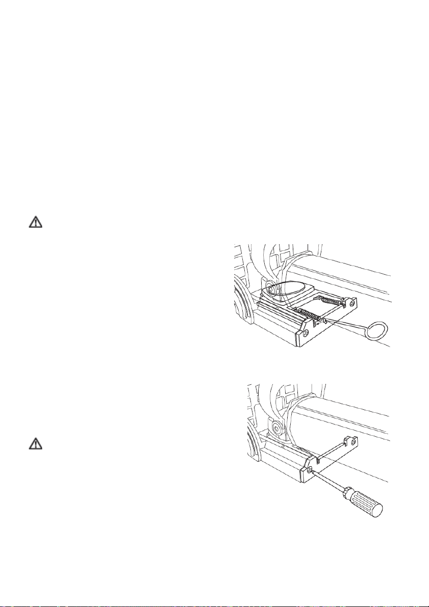
Changing the blade.........................................................................................................................10
Using the dust bag..........................................................................................................................11
Adjusting the depth of cut ...............................................................................................................11
Using the plunge depth stop...........................................................................................................12
Starting the tool...............................................................................................................................13
Making a cut....................................................................................................................................13
Machine maintenance.....................................................................................................................14
APPLICATIONS...................................................................................................................................14
Edge To Edge Joint ........................................................................................................................14
T-Joint.............................................................................................................................................15
Frame Joint.....................................................................................................................................16
Edge Miter Joint..............................................................................................................................16
Corner joint .....................................................................................................................................18
MAINTENANCE & INSPECTION........................................................................................................19
Service............................................................................................................................................19
Power Cord.....................................................................................................................................19
Tool Lubrication ..............................................................................................................................19
Ventilation Openings.......................................................................................................................19
Bearings..........................................................................................................................................19
Inspect Accessories........................................................................................................................19
Inspect Screws................................................................................................................................19
ACCESSORIES...................................................................................................................................20
Standard Accessories.....................................................................................................................20
SERVICE LOCATIONS .......................................................................................................................20

3
TABLE DES MATIÈRES
SÉCURITÉ...........................................................................................................................................21
Règles générales de sécurité .........................................................................................................21
Consignes de sécurité pour raboteuse...........................................................................................23
Description bréve............................................................................................................................23
Double isolation ..............................................................................................................................23
Rallonges èlectriques .....................................................................................................................23
DESCRIPTIONS & SPÉCIFICATIONS ...............................................................................................24
Diagramme des pièces et caractéristiques.....................................................................................24
Symboles........................................................................................................................................25
Specifications..................................................................................................................................25
ASSEMBLAGE & UTILISATION.........................................................................................................26
Avant l’utilisation.............................................................................................................................26
Changement de la lame..................................................................................................................26
Utilisation du sac à poussiére.........................................................................................................27
Ajustement de la profondeur de coupe...........................................................................................27
Ajustement du guide.......................................................................................................................28
Mise en marche de l’outil................................................................................................................29
Faire une coupe..............................................................................................................................29
Maintenance ...................................................................................................................................30
APPLICATIONS...................................................................................................................................30
Joints bout à bout ...........................................................................................................................30
Joints en T ......................................................................................................................................31
Joints de cadre................................................................................................................................32
Joints à onglet.................................................................................................................................32
Joints d’angle..................................................................................................................................34
MAINTENANCE & INSPECTION........................................................................................................35
Service............................................................................................................................................35
Cordon d’alimentation.....................................................................................................................35
Lubrification de la machine.............................................................................................................35
Conduits d'aération.........................................................................................................................35
Roulements.....................................................................................................................................35
Inspection des accessoires.............................................................................................................35
Inspection des vis ...........................................................................................................................35
ACCESSOIRES...................................................................................................................................36
Accessoires standards....................................................................................................................36
POINTS DE SERVICE.........................................................................................................................36

4
TABLA DE CONTENIDOS
SEGURIDAD........................................................................................................................................37
Advertencias de seguridad generales para las herramientas eléctricas ........................................37
Advertencias de seguridad de la engalletadora..............................................................................39
Descripción abreviada ....................................................................................................................39
Doble aislamiento ...........................................................................................................................39
Alargadores eléctricos ....................................................................................................................39
DESCRIPCION Y ESPECIFICACIONES ............................................................................................40
Diagrama de partes y características.............................................................................................40
Símbolos.........................................................................................................................................41
Especificaciones.............................................................................................................................41
MONTAJE Y FUNCIONAMIENTO ......................................................................................................42
Antes de utilizar la herramienta ......................................................................................................42
Cambio de la cuchilla......................................................................................................................42
Uso de la bolsa para polvo .............................................................................................................43
Ajuste de la profundidad de corte...................................................................................................43
Ajustes del tope ..............................................................................................................................44
Encendido de la herramienta..........................................................................................................45
Ejecución del corte..........................................................................................................................45
Mantenimiento de la herramienta ...................................................................................................46
APLICACIONES..................................................................................................................................46
Unión de borde con borde ..............................................................................................................46
Unión en T ......................................................................................................................................47
Unión de marcos.............................................................................................................................48
Uniones en ángulo..........................................................................................................................48
Unión de esquina............................................................................................................................50
MANTENIMIENTO E INSPECCION....................................................................................................51
Servicio...........................................................................................................................................51
Cable de alimentación ....................................................................................................................51
Lubricación de la herramienta ........................................................................................................51
Aberturas de ventilación .................................................................................................................51
Rodamientos...................................................................................................................................51
Inspeccione los accesorios.............................................................................................................51
Inspeccione los tornillos..................................................................................................................51
ACCESORIOS.....................................................................................................................................52
Accesorios de serie.........................................................................................................................52
CENTROS DE SERVICIO....................................................................................................................52

5
SAFETY
GENERAL POWER TOOL SAFETY WARNINGS
WARNING Read all safety warnings and all instructions. Failure to follow the warnings and
instructions may result in electric shock, fire and/or serious injury.
Save all warnings and instructions for future reference.
The term "power tool" in the warnings refers to your mains-operated (corded) power tool or battery-
operated (cordless) power tool.
1) Work area safety
a) Keep work area clean and well lit. Cluttered or dark areas invite accidents.
b) Do not operate power tools in explosive atmospheres, such as in the presence of
flammable liquids, gases or dust. Power tools create sparks which may ignite the dust or
fumes.
c) Keep children and bystanders away while operating a power tool. Distractions can cause
you to lose control.
2) Electrical safety
a) Power tool plugs must match the outlet. Never modify the plug in any way. Do not use
any adapter plugs with earthed (grounded) power tools. Unmodified plugs and matching
outlets will reduce risk of electric shock.
b) Avoid body contact with earthed or grounded surfaces, such as pipes, radiators,
ranges and refrigerators. There is an increased risk of electric shock if your body is earthed
or grounded.
c) Do not expose power tools to rain or wet conditions. Water entering a power tool will
increase the risk of electric shock.
d) Do not abuse the cord. Never use the cord for carrying, pulling or unplugging the
power tool. Keep cord away from heat, oil, sharp edges or moving parts. Damaged or
entangled cords increase the risk of electric shock.
e) When operating a power tool outdoors, use an extension cord suitable for outdoor use.
Use of a cord suitable for outdoor use reduces the risk of electric shock.
f) If operating a power tool in a damp location is unavoidable, use a ground fault circuit
interrupter (GFCI) protected supply. Use of an GFCI reduces the risk of electric shock.
3) Personal safety
a) Stay alert, watch what you are doing and use common sense when operating a power
tool. Do not use a power tool while you are tired or under the influence of drugs,
alcohol or medication. A moment of inattention while operating power tools may result in
serious personal injury.
b) Use personal protective equipment. Always wear eye protection. Protective equipment
such as dust mask, non-skid safety shoes, hard hat, or hearing protection used for
appropriate conditions will reduce personal injuries.
c) Prevent unintentional starting. Ensure the switch is in the off-position before
connecting to power source and/or battery pack, picking up or carrying the tool.
Carrying power tools with your finger on the switch or energising power tools that have the
switch on invites accidents.

6
d) Remove any adjusting key or wrench before turning the power tool on. A wrench or a
key left attached to a rotating part of the power tool may result in personal injury.
e) Do not overreach. Keep proper footing and balance at all times. This enables better
control of the power tool in unexpected situations.
f) Dress properly. Do not wear loose clothing or jewellery. Keep your hair, clothing and
gloves away from moving parts. Loose clothes, jewellery or long hair can be caught in
moving parts.
g) If devices are provided for the connection of dust extraction and collection facilities,
ensure these are connected and properly used. Use of dust collection can reduce dust-
related hazards.
4) Power tool use and care
a) Do not force the power tool. Use the correct power tool for your application. The correct
power tool will do the job better and safer at the rate for which it was designed.
b) Do not use the power tool if the switch does not turn it on and off. Any power tool that
cannot be controlled with the switch is dangerous and must be repaired.
c) Disconnect the plug from the power source and/or the battery pack from the power tool
before making any adjustments, changing accessories, or storing power tools. Such
preventive safety measures reduce the risk of starting the power tool accidentally.
d) Store idle power tools out of the reach of children and do not allow persons unfamiliar
with the power tool or these instructions to operate the power tool. Power tools are
dangerous in the hands of untrained users.
e) Maintain power tools. Check for misalignment or binding of moving parts, breakage of
parts and any other condition that may affect the power tool’s operation. If damaged,
have the power tool repaired before use. Many accidents are caused by poorly maintained
power tools.
f) Keep cutting tools sharp and clean. Properly maintained cutting tools with sharp cutting
edges are less likely to bind and are easier to control.
g) Use the power tool, accessories and tool bits etc. in accordance with these
instructions, taking into account the working conditions and the work to be performed.
Use of the power tool for operations different from those intended could result in a hazardous
situation.
5) Service
a) Have your power tool serviced by a qualified repair person using only identical
replacement parts. This will ensure that the safety of the power tool is maintained.

7
JOINTER SAFETY WARNINGS
•Disc cutters must be rated for at least the speed recommended on the tool. Disc cutters
running over rated speed can fly apart and cause injury.
•Always use the guard. The guard protects the operator from broken disc cutter fragments and
unintentional contact with the disc cutter.
BRIEF DESCRIPTION
The Felisatti RF100/710 biscuit joiner is intended solely for cutting slots for biscuits in solid wood and
wood related materials such as MDF, particle board, plywood, etc. Any alternative use of this
machine would be considered a failure to comply with the intended purpose of the machine. The
manufacturer is not liable for any damage or injury arising from the improper use of this machine and
the user assumes sole responsibility in this case.
DOUBLE INSULATION
To ensure safer operation of this tool, Felisatti has adopted a double insulation design. "Double
Insulation" means that two physically separated insulation systems have been used to insulate the
electrically conductive materials connected to the power supply from the outer frame handled by the
operator.
To keep the double insulation system effective, follow these precautions:
• Be careful not to pierce the motor housing as this could damage the efficiency of the double
insulation system.
• Only Felisatti Authorized Service Centers should disassemble or assemble this power tool, and only
genuine Felisatti replacement parts should be installed.
EXTENSION CORDS
Make sure your extension cords are in good condition. Make sure you use an extension cord that is
heavy enough to carry the current your tool requires. An undersized cord will cause a drop in voltage
which creates a loss of power and could cause your tool to overheat. Please utilize the table below to
identify the proper gauge cord for the tool you are using. Remember, the lower the number, the
heavier gauge the cord. If you are unsure as to which gauge cord you need, use the next heavier
gauge.

8
DESCRIPTIONS & SPECIFICATIONS
WARNING: Disconnect the plug from the power source before making any assembly,
adjustments or changing accessories. Such preventive safety measures reduce the risk of starting
the tool accidentally.
FUNCTIONAL DESCRIPTION
A – Switch Control
B - Auxiliary grip
C - Adjustable Stop
D - Moveable square
E - Blocking stop adjustment knob
F - Fence Angle Scale
G - Rack & Pinion Knob
H - Locking Lever
I - Support base/saw blade protection
J - Back Cover
K - Anti-Slip Pads
L - Saw blade replacement blocking button
M - Rear Housing Cover
N - Depth adjustment divisions
O - Depth Adjusting Screw
P - Dust extraction nozzle
Q - Blade Wrench
R - Dust Bag
T - Spring Removal Tool
U - Hex Nut Wrench

9
SYMBOLS
Some of the following symbols may be used on your tool. Please study them and learn their meaning.
Proper interpretation of these symbols will allow you to operate the tool better and safer.
Symbol Name Designation/Explanation
V Volts Voltage (potential)
A Amperes Current
Hz Hertz Frequency (cycles per second)
W Watt Power
(n0) No load speed Rotational speed, at no load
.../min Revolutions or reciprocation per minute Revolutions, strokes, surface speed,
orbits, etc. per minute
Class II construction Designates double insulated construction
tools
Alternating current Type or a characteristic of current
Safety Alert Precautions that involve your safety
SPECIFICATIONS
Power Source Single-Phase, 120V ~ 60Hz
Amps 6,5
No-Load Speed 9000 RPM
Blade Diameter 3-15/16" (100mm)
Blade Arbor Size 0-25/64” (22mm)
Biscuit Sizes 0, 10, 20, A, B, Max
Max. Depth of Cut 0-25/32" (20mm)
Approx. Tool Weight 6.8 lbs. (3.6 Kg)
Indicates that the product was tested and has met the certification requirements for
electrical products.

10
ASSEMBLY & OPERATION
PRIOR TO OPERATION
1. Check Power Supply
Ensure that the power source to be utilized conforms to the power source requirements specified on
the tool nameplate. Ensure the receptacle being used accepts the plug tightly. If a faulty receptacle is
used, it may cause overheating, resulting in a serious hazard.
2. Check Work Area
Confirm that the work site is placed under appropriate conditions conforming to precautions
prescribed in the safety section of this manual.
3. Before Plugging in the Tool
Ensure that the power tool switch is in the OFF position to prevent the tool from accidental start up,
which could cause serious injury.
CHANGING THE BLADE
WARNING: Disconnect tool from power source
before installing or removing the blade.
CAUTION: Be careful when removing or installing
the blade as it is extremely sharp and could be hot
after use Improper care when handling blades can
cause severe cuts and severe burns.
Use the spring release / locating hook supplied with
the machine to disconnect the two springs, one on
either side of the machine.Fig.1A
Remove the two horizontal screws holding the
plastic end cap at the rear of the blade housing and
remove the end cap.Fig.1B
Slide the blade housing forwards and remove
completely.
Depress the spindle lock button to lock the spindle.
Use the pin wrench to release the top flange on top
of the blade.
Be careful, the teeth on the blade are sharp
and can cause injury.
Remove the top flange, blade and lower flange
completely and clean any sawdust and resin from
the spindle, blade flanges, blade housing and slide
tracks. Fig.1C
Ensure that the lower flange and blade seat
correctly before fitting the top flange.
Fig. 1A
Fig. 1B

11
CHANGING THE BLADE
Be careful, the teeth on the blade are sharp
and can cause injury.
Remove the top flange, blade and lower flange
completely and clean any sawdust and resin from
the spindle, blade flanges, blade housing and slide
tracks. Fig.1C
Ensure that the lower flange and blade seat
correctly before fitting the top flange.
Ensure that the blade is fitted the correct
way up.
Fit the top flange, check that it seats correctly and
finger tighten. Fully tighten the flange using the pin
wrench and locking spindle with spindle lock button.
Lightly oil the slide assembly using the plastic
lubricating bottle supplied (use a thin machine oil to
refill the bottle when empty).
Replace the plastic end cap and tighten the two
screws.
Use the spring release / locating hook to refit the
two springs.
Fig. 1C
USING THE DUST BAG - Fig. 2
1. To attach the Dust Bag (R), fit it over the nozzle
of the Dust Exhaust Tube (P) on the joiner
2. To empty the dust bag, first turn off and
disconnect the machine from its power source
Remove the dust bag from the exhaust tube and
unzip the bag to empty the sawdust
Fig. 2
ADJUSTING THE DEPTH OF CUT
The machine is preset to cut at 6 different depths
Setting on Plunge
Depth Stop 0 10 20 A B Max
Biscuit Size 0 10 20 N/A N/A N/A
Depth of Cut 5/ 6”
8mm 13/32”
10.4mm 15/32”
11.9mm 1/2”
12.7mm 19/32”
15mm 25/32”
19.9mm
Width of Cut 2 5/32”
54.8mm 2 3/8”
60.4mm 2 9/ 6”
65.2mm 2 2 /32”
67.5mm 2 3/ 6”
71.4mm 2 29/32”
73.8mm

12
USING THE PLUNGE DEPTH STOP– FIG. 3
1. To select the desired depth of cut simply rotate
the Plunge Depth Stop (N) until the desired
setting corresponds to the red indicator line.
2. Fine adjustments can be made to the depth
of cut by turning the Adjusting Screw (O). First
unlock the hex nut on the adjusting screw then
turn the screw left to increase depth of cut and
right to decrease depth of cut Remember to
tighten hex nut once the screw is adjusted.
Fig. 3
FENCE ADJUSTMENTS
Using the Adjustable Fence – Fig. 4
1. The Adjustable Fence (C) can be adjusted from
0° to 90° and has positive stops at 0°, 45°, and 90°
2. To adjust the fence, first loosen the Fence Lock
Knob (E).
3. Tilt the Adjustable Fence until the red indicator
line corresponds to the desired angle on the Fence
Angle Scale (F) and tighten the Fence Lock Knob.
Using the Angle Plate – Fig. 5
1. The Angle Plate (D) can be moved up and down
to adjust the blade to the thickness of the wood.
2. To move the Angle Plate, first unlock the
Locking Lever (H).
3. Raise and lower the Angle Plate by turning
the Rack & Pinion Knob (G) clockwise to raise
the Angle Plate and counter clockwise to lower
the plate.
4. Once the Angle Plate reaches the desired setting
lock the Locking Lever.
NOTE: In some applications it will be necessary to
remove the angle plate To remove the plate, loosen
the locking lever and rotate the rack & pinion knob
clockwise until the angle plate clears the top of the
adjustable fence.
Fig. 4
Fig. 5

13
STARTING THE TOOL – Fig. 6
WARNING: Make sure that the voltage from the
power supply matches the voltage specified on the
tool Before plugging in the tool ensure the blade is
properly installed and tightened.
1. Plug the tool in with the switch in the “OFF”
Position.
2. Hold the machine firmly by the Auxiliary Handle
(B) and Rear Housing Cover (M).
3. Turn the machine “ON” by pushing the On/Off
switch (A) towards the rear of the machine.
4. Turn the machine “OFF” by pushing the On/Off
switch (A) towards the front of the machine.
Fig. 6
MAKING A CUT – Fig. 7
1. With the machine unplugged and the switch
in the “Off” position, make sure the blade and all
adjustment knobs are tight.
2. Make sure the workpiece is securely clamped to
a work surface.
3. Plug in the machine.
4. Align the joiner’s center mark with the layout
mark on the workpiece.
5. With both hands firmly holding the auxiliary
handle and rear housing cover turn on the
machine and allow the blade to come up to full
speed.
6. With the machine squarely positioned on the
workpiece, plunge the blade into the workpiece
until the machine bottoms out on the plunge
depth stop.
7. Retract the blade from the cut and turn the
machine off.
Fig. 7

14
MACHINE MAINTENANCE – Fig. 8
1. From time to time, a small amount of oil should
be placed in each of the tracks of the Base (I) to
keep the mechanism sliding properly.
2. Insert the nozzle of the included Oil Bottle
(S) into the holes on each side of the base and
squeeze out two or three drops of oil.
3. During heavy use it may be necessary to
lubricate the machine a couple of times a week,
but not so often that the oil builds up too heavily
on the sliding assembly.
Fig. 8
APPLICATIONS
Edge To Edge Joint – Fig. 9
This is a very simple joint and is commonly
used when gluing up boards for projects such
as table tops.
1. Lay out the workpieces exactly like they will
be assembled.
2. Use a straight edge to mark layout marks on
each workpiece where a biscuit will be inserted
Be sure to locate biscuits at least 2” from the
end of the workpiece and space each biscuit
about 4”-6” apart –Fig. 9A
3. Set the plunge depth setting on the biscuit
joiner to match the biscuits being used and
set the angle fence on the biscuit joiner to the
proper height.
4. Clamp the workpiece to a stable work
surface and align the center mark on the joiner
to the first layout mark Turn on the machine
and make the first plunge cut Retract the
plunge and turn off the machine Slide the
machine to the second layout mark and repeat
the process –Fig. 9B
Fig. 9
5. Add glue and biscuits to each slot, assemble, and clamp until the glue is dry
NOTE: This machine is designed to cut into the center of a ¾” board without the use of the
angle plate In applications such as edge to edge joints where there are no mitered edges, the
joiner and material to be cut can sit flat on the work surface when making the cuts.

15
T-Joint – Fig. 10
This joint is commonly used in bookshelf
applications to attach the shelf to the side of
the case In this application remove the angle
plate from the machine.
1. Align the workpieces on a work surface in
the manner that they will be joined.
2. Lightly scribe a line on the frame where
the top of the shelf will be positioned once it
is attached Scribe layout lines indicating the
biscuit locations on the shelf board –Fig. 10A
3. Clamp the shelf board to the frame along
the line scribed with the biscuit layout lines
facing up.
Fig. 10
4. Select the proper biscuit size on your joiner
and remove the angle plate.
5. Align the joiner to make the vertical cuts by
registering the centerline on the bottom side of
the base with your layout marks –Fig. 10B
6. Align the joiner to make the horizontal cuts
by using the center mark on the top side of the
base –Fig. 10C
7. Make the cuts, add glue and biscuits,
assemble, and clamp until the glue is dry.
Fig. 10

16
Frame Joint – Fig. 11
Frame joints are very simple yet strong joints and
are very common in applications such as picture
frames and door and window moldings.
1. Layout the workpiece on a work surface
exactly as they are to be joined.
2. Scribe layout lines across each piece at the
location of the biscuit – Fig. 11A
3. Select the proper biscuit size on the plunge
depth stop and adjust the angle plate to the
proper height.
4. Clamp the workpiece to a work surface and
position the joiner with the layout line Turn on
the machine and make the cut – Fig. 11B
5. Repeat step 4 on the second workpiece.
6. Insert glue and biscuits, assemble, and clamp
until the glue is dry.
Fig. 11
Edge Miter Joint
Edge miter joints are strong joints commonly
used for making boxes and applications such
as multi-sided surrounds There are two types
joining applications for edge miter joints:
1) Aligning on the outside of the joint and
2) Aligning on the inside of the joint
Outside Alignment - 90° joint only – Fig. 12
1. Lay out the workpieces on a work surface
exactly as they are to be joined.
2. Mark layout lines on the outside of the joint
on both workpieces – Fig. 12A
3. Set the height of the angle plate so the cut
will enter the workpiece where the material is
thicker.
4. Select a biscuit size that will not require the
joiner to cut completely through the joint.
5. Clamp the workpiece vertically and align the
outside of the joint with the 45° notch cut on
the underside of the angle plate Make the cut
– Fig. 12B
6. Repeat the cut on the second workpiece.
7. Insert glue and biscuits, assemble, and clamp
until the glue is dry.
Fig. 12

17
Inside Alignment - 90° joint – Fig. 13
1. Lay out the workpieces on a work surface
exactly as they are to be joined.
2. Mark layout lines on the inside of the joint
on both workpieces – Fig. 13A
3. Remove the angle plate from the joiner and
set the adjustable fence to the 45° setting.
4. Select a biscuit size that will not require the
joiner to cut completely through the joint.
5. Clamp the workpiece to a work surface with
the mitered edge facing up.
Fig. 13
6. Align the joiner as shown in Fig. 1 2 and make
the cut. – Fig. 13B
7. Repeat the cut on the second workpiece.
8. Insert glue and biscuits, assemble, and
clamp until the glue is dry.
Use this chart for the proper fence setting for
joints other than 90º.
# Sides Fence Angle for
Inside Alignment
4 90°
5 81°
6 75°
8 67.5°
Fig. 13B

18
Corner joint – Fig. 14
A corner joint is a common joining technique
where a T-joint is used for applications such as
boxes and drawers.
1. Lay out the workpieces on a work surface
exactly as they are to be joined.
2. Mark layout lines across the face of one
board and outward edge of the second board.
– Fig. 14A
3. Select the proper biscuit size on the plunge
depth stop and set the angle fence to the
appropriate height.
4. For the edge cut, clamp the workpiece to a
work surface, align the center mark of the joiner
to the layout line and make the cut. – Fig. 14B
5. For the face cut, clamp the workpiece
vertically and make the cut as shown in
Fig. 14C. Do not change the height of the angle
plate from the edge cut to the face cut.
6. Insert glue and biscuits, assemble, and clamp
until the glue is dry.
Fig. 14

19
MAINTENANCE & INSPECTION
MAINTENANCE
Service
It is recommended that all service on your Felisatti tool be performed by an Authorized Felisatti
service center. Service by unauthorized service personnel may result in misplaced internal
components resulting in risk of tool malfunction and personal injury to the tool user.
Power Cord
Check that the power cord is in good condition. If it is not, have it replaced immediately at a Felisatti
Authorized service center.
Tool Lubrication
All power tools require care and attention. Every couple of years, we recommend leaving the tool with
an authorized Felisatti service center for a general cleaning and lubrication.
Ventilation Openings
Make sure the air vents are always kept clean and free of obstacles. If clogged, vacuum out
obstruction. It is recommended that you blow off the entire tool with compressed air after each use.
Bearings
Bearings that become very noisy should be replaced at once to avoid overheating or motor failure.
Inspect Accessories
Regularly inspect your blades. Using worn accessories with diminish the efficiency of the work and
could damage the tool’s motor.
Inspect Screws
Regularly inspect all screws in your power tool and make sure they are properly tightened. Loose
screws should be retightened immediately.

20
ACCESSORIES
ACCESSORIES
Standard Accessories
• Blade wrench
• Dust Bag
• Biscuits
• Oil Bottle
• Spring Removal Tool
• Wrench
• Owner’s Manual
• Carrying Case
SERVICE LOCATIONS
SERVICE
To locate a Felisatti Authorized Service Center near you, visit our web site at: www.felisatti.es
Other manuals for RF100/710
1
Table of contents
Languages: