DeWalt DCW682 User manual

final page size: 8.5 x 5.5 in
If you have questions or comments, contactus.
Pour toute question ou tout commentaire, nouscontacter.
Si tiene dudas o comentarios,contáctenos.
1‑800‑4‑DeWALT
DCW682
Biscuit Joiner
Fraiseuse à lamelles
Ensambladora de Galletas
Instruction Manual
Guide D’utilisation
Manual de instrucciones

English (original instructions) 10
Français (traduction de la notice d’instructions originale) 20
Español (traducido de las instrucciones originales) 32

1
Fig. A
Components
1 Paddle switch
2 Lock‑off switch
3 Auxiliary handle
4 Fence height adjuster
5 Dust extraction outlet
6 Adjustable fence
7 Anti‑slipping pins
8 Plunge depth adjusting knob
9 Locking knob
10 Spindle lock
11 Adjustable fence locking knob
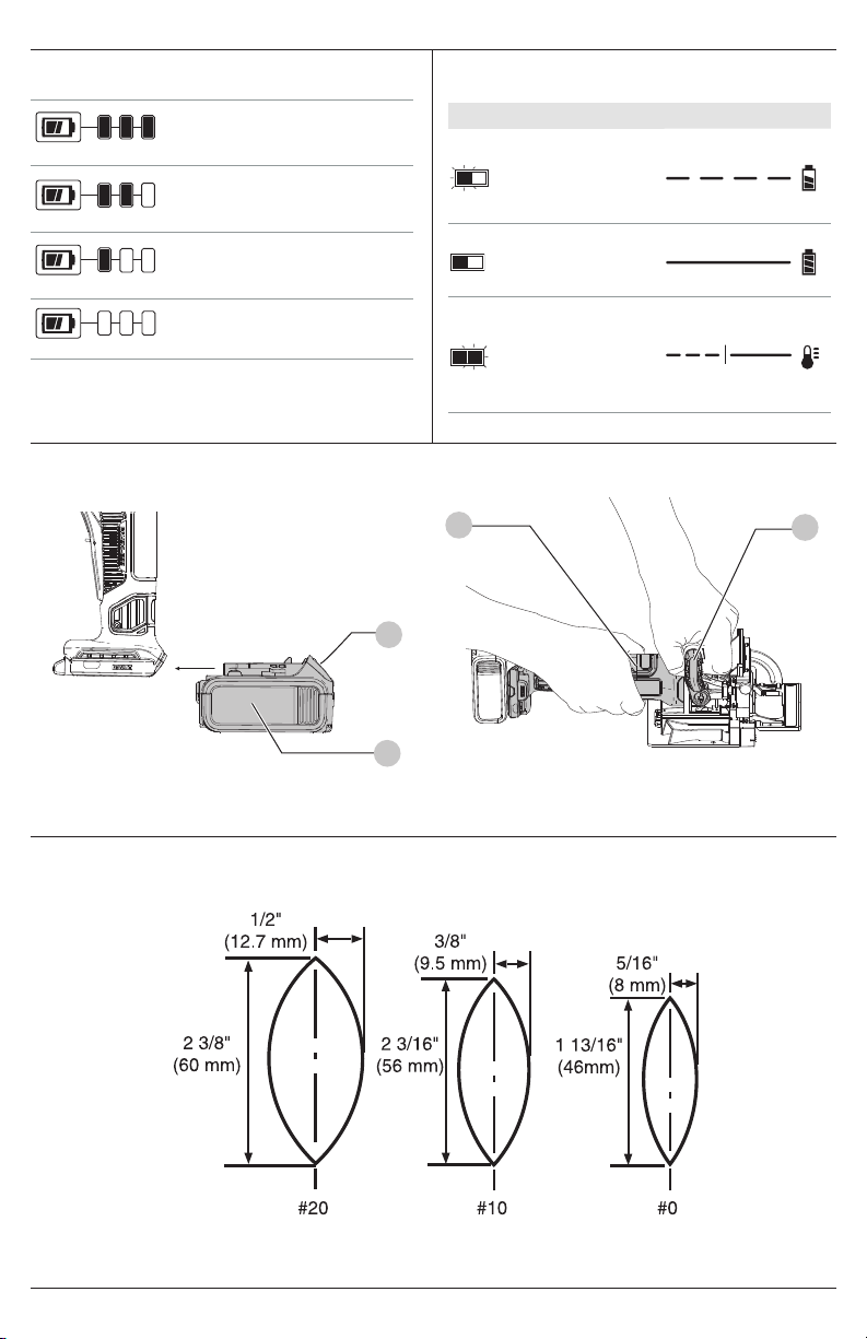
12 Battery
13 Battery release
Composants
1 Interrupteur à palette
2 Levier de verrouillage
3 Poignée supérieure
4 Molette de réglage
5 Dépoussiérage de la poussière
6 Guide réglable
7 Goupilles anti‑glissement
8 Bouton de réglage de la
profondeur
9 Bouton de verrouillage
10 Verrouillage de la tige
11 Bouton de verrouillage du guide
réglable
12 Bloc‑piles
13 Bouton de libération du bloc‑piles
Componentes
1 Interruptor de paleta
2 Bloqueo de apagado
3 Empuñadura superior
4 Perilla de ajuste estriada
5 Puerto de extracción de polvo
6 Uía ajustable
7 Pasadores antideslizantes
8 Perilla de ajuste de profundidad
9 Perilla de bloqueo
10 Bloqueo de husillo
11 Perilla de bloqueo de valla
ajustable
12 Paquete de batería
13 Botón de liberación de batería
3
4
5
8
7
11
1
6
9
12
13
2
10

2
Fig.B Fig.C
Fig.D1 Fig.D2
Fig.E
12
13
75–100% charged
Chargé de 75 à 100 %
75–100% cargada
51–74% charged
Chargé de 51 à 74 %
51–74% cargada
< 50% charged
Chargé de < 50 %
< 50% cargada
Pack needs to be charged
Le bloc‑piles doit être rechargé
La batería tiene que cargarse
Indicators/Témoin/Indicador
Charging
Bloc‑piles en Cours
de Chargement
Unidad en Proceso de Carga
Fully Charged
Bloc‑piles Chargé
Unidad Cargada
Hot/Cold Pack Delay
Suspension de Charge Contre
le Chaud/Froid
Restraso por Unidad Caliente/
Fría
3
18

3
Fig. F

4
Fig.G Fig.H
Fig.I Fig.J
Fig.L
Fig.K
8
6
94
5
16
6
21
14
7

5
Fig.M1 Fig.M2
15
5
15
19
20
17
Fig. N Fig. O
Fig.P Fig. Q

6
Fig.R
Fig. W
Fig. T
Fig. V
Fig. U
Fig.S
5-7.5 cm 15-25 cm 15-25 cm
3/16" (5 mm) minimum
Minimum de 5 mm (3/16 po)
4,7 mm (3/16") minimo
3/16" (5 mm) minimum
Minimum de 5 mm (3/16 po)
4,7 mm (3/16") minimo
3/16" Minimum
Minimum de 5 mm (3/16 po)
4,7 mm (3/16") minimo

7
Fig. X Fig.Y
Fig.Z Fig.AA
Fig.BB

8
Fig.CC

9
Fig.DD
Fig.FF
Fig.HH
Fig.EE
Fig.GG

ENGLISH
10
b ) Do not operate power tools in explosive
atmospheres, such as in the presence of
flammable liquids, gases or dust. Power tools create
sparks which may ignite the dust orfumes.
c ) Keep children and bystanders away while
operating a power tool. Distractions can cause you
to losecontrol.
2) Electrical Safety
a ) Power tool plugs must match the outlet. Never
modify the plug in any way. Do not use any
adapter plugs with earthed (grounded) power
tools. Unmodified plugs and matching outlets will
reduce risk of electricshock.
b ) Avoid body contact with earthed or grounded
surfaces, such as pipes, radiators, ranges and
refrigerators. There is an increased risk of electric
shock if your body is earthed orgrounded.
c ) Do not expose power tools to rain or wet
conditions. Water entering a power tool will increase
the risk of electricshock.
d ) Do not abuse the cord. Never use the cord for
carrying, pulling or unplugging the power tool.
Keep cord away from heat, oil, sharp edges or
moving parts. Damaged or entangled cords increase
the risk of electricshock.
e ) When operating a power tool outdoors, use an
extension cord suitable for outdoor use. Use of
a cord suitable for outdoor use reduces the risk of
electricshock.
f ) If operating a power tool in a damp location
is unavoidable, use a ground fault circuit
interrupter (GFCI) protected supply. Use of a GFCI
reduces the risk of electricshock.
3) Personal Safety
a ) Stay alert, watch what you are doing and use
common sense when operating a power tool. Do
not use a power tool while you are tired or under
the influence of drugs, alcohol or medication. A
moment of inattention while operating power tools
may result in serious personalinjury.
b ) Use personal protective equipment. Always wear
eye protection. Protective equipment such as a dust
mask, non‑skid safety shoes, hard hat, or hearing
protection used for appropriate conditions will reduce
personalinjuries.
c ) Prevent unintentional starting. Ensure the switch
is in the off‑position before connecting to power
source and/or battery pack, picking up or carrying
the tool. Carrying power tools with your finger on the
switch or energizing power tools that have the switch
on invitesaccidents.
d ) Remove any adjusting key or wrench before
turning the power tool on. A wrench or a key left
attached to a rotating part of the power tool may result
in personalinjury.
e ) Do not overreach. Keep proper footing and
balance at all times. This enables better control of the
power tool in unexpectedsituations.
GENERAL POWER TOOL SAFETY WARNINGS
WARNING: Read all safety warnings, instructions,
illustrations and specifications provided with
this power tool. Failure to follow all instructions
listed below may result in electric shock, fire and/or
seriousinjury.
SAVE ALL WARNINGS AND
INSTRUCTIONS FOR FUTURE REFERENCE.
The term “power tool” in the warnings refers to your
mains‑operated (corded) power tool or battery‑operated
(cordless) powertool.
1) Work Area Safety
a ) Keep work area clean and well lit. Cluttered or dark
areas inviteaccidents.
Definitions: Safety Alert Symbols and Words
This instruction manual uses the following safety alert
symbols and words to alert you to hazardous situations and
your risk of personal injury or propertydamage.
DANGER: Indicates an imminently hazardous
situation which, if not avoided, will result in death or
seriousinjury.
WARNING: Indicates a potentially hazardous situation
which, if not avoided, could result in death or
seriousinjury.
CAUTION: Indicates a potentially hazardous situation
which, if not avoided, may result in minor or
moderateinjury.
(Used without word) Indicates a safety
relatedmessage.
NOTICE: Indicates a practice not related to
personal injury which, if not avoided, may result in
propertydamage.
Intended Use
You have purchased a precision woodworking tool.
The function of the biscuit joiner is to enable you to
make extremely strong and accurate joints in wood and
woodbyproducts.
The tool uses a plunging action to precisely cut crescent
shaped slots for the placement of flat wooden dowels or
“biscuits” like those shown in FigureE.
The various adjustments on the patented base/fence
assembly will enable you to make virtually any biscuit joint
imaginable. The tool may be further enhanced by some
simple jigs and fixtures that can be easily made. Some of
the more common biscuit joinery applications are shown
in Figure F and are discussed in detail in the applications
section of thismanual.
English (original instructions)
WARNING: Read all safety warnings and all
instructions. Failure to follow the warnings and
instructions may result in electric shock, fire and/or
seriousinjury.
WARNING: To reduce the risk of injury, read the
instructionmanual.

11
ENGLISH
Additional Specific Safety Instructions
• Blades must be rated for at least the speed marked
on the tool. Blades running over rated speed can fly apart
and causeinjury.
• Always use the guard. The guard protects the operator
from broken blade fragments and unintentional contact
with theblade.
• Hold power tool by insulated gripping surfaces
because the cutter may contact its own cord. Cutting a
“live” wire may make exposed metal parts of the power tool
“live” and could give the operator an electricshock.
• Do not use blunt or damaged blades. Personal injury
mayoccur.
• Keep guards in working order. Check operation
before each use. Do not use if guard does not close briskly
overblade.
• Air vents often cover moving parts and should be
avoided. Loose clothes, jewelry or long hair can be caught
in movingparts.
b ) Use power tools only with specifically designated
battery packs. Use of any other battery packs may
create a risk of injury andfire.
c ) When battery pack is not in use, keep it away
from other metal objects, like paper clips, coins,
keys, nails, screws or other small metal objects,
that can make a connection from one terminal to
another. Shorting the battery terminals together may
cause burns or afire.
d ) Under abusive conditions, liquid may be ejected
from the battery; avoid contact. If contact
accidentally occurs, flush with water. If liquid
contacts eyes, additionally seek medical help.
Liquid ejected from the battery may cause irritation
orburns.
e ) Do not use a battery pack or tool that is damaged
or modified. Damaged or modified batteries may
exhibit unpredictable behavior resulting in fire,
explosion or risk ofinjury.
f ) Do not expose a battery pack or tool to
fire or excessive temperature. Exposure to
fire or temperature above 265°F (130°C) may
causeexplosion.
g ) Follow all charging instructions and do not
charge the battery pack or tool outside the
temperature range specified in the instructions.
Charging improperly or at temperatures outside the
specified range may damage the battery and increase
the risk offire.
6) Service
a ) Have your power tool serviced by a qualified
repair person using only identical replacement
parts. This will ensure that the safety of the power tool
ismaintained.
b ) Never service damaged battery packs. Service
of battery packs should only be performed by the
manufacturer or authorized serviceproviders.
f ) Dress properly. Do not wear loose clothing or
jewelry. Keep your hair, clothing and gloves away
from moving parts. Loose clothes, jewelry or long
hair can be caught in movingparts.
g ) If devices are provided for the connection of dust
extraction and collection facilities, ensure these
are connected and properly used. Use of dust
collection can reduce dust‑relatedhazards.
h ) Do not let familiarity gained from frequent use of
tools allow you to become complacent and ignore
tool safety principles. A careless action can cause
severe injury within a fraction of asecond.
4) Power Tool Use and Care
a ) Do not force the power tool. Use the correct power
tool for your application. The correct power tool
will do the job better and safer at the rate for which it
wasdesigned.
b ) Do not use the power tool if the switch does not
turn it on and off. Any power tool that cannot be
controlled with the switch is dangerous and must
berepaired.
c ) Disconnect the plug from the power source and/
or remove the battery pack, if detachable, from
the power tool before making any adjustments,
changing accessories, or storing power tools. Such
preventive safety measures reduce the risk of starting
the power toolaccidentally.
d ) Store idle power tools out of the reach of children
and do not allow persons unfamiliar with the
power tool or these instructions to operate the
power tool. Power tools are dangerous in the hands of
untrainedusers.
e ) Maintain power tools and accessories. Check
for misalignment or binding of moving parts,
breakage of parts and any other condition
that may affect the power tool’s operation. If
damaged, have the power tool repaired before
use. Many accidents are caused by poorly maintained
powertools.
f ) Keep cutting tools sharp and clean. Properly
maintained cutting tools with sharp cutting edges are
less likely to bind and are easier tocontrol.
g ) Use the power tool, accessories and tool bits etc.
in accordance with these instructions, taking
into account the working conditions and the
work to be performed. Use of the power tool for
operations different from those intended could result in
a hazardoussituation.
h ) Keep handles and grasping surfaces dry, clean
and free from oil and grease. Slippery handles and
grasping surfaces do not allow for safe handling and
control of the tool in unexpectedsituations.
5) Battery Tool Use and Care
a ) Recharge only with the charger specified by the
manufacturer. A charger that is suitable for one type
of battery pack may create a risk of fire when used with
another batterypack.

ENGLISH
12
READ ALL INSTRUCTIONS
Important Safety Instructions for All
Battery Packs
WARNING: Read all safety warnings, instructions,
and cautionary markings for the battery pack,
charger and product. Failure to follow the
warnings and instructions may result in electric
shock, fire and/or seriousinjury.
• Do not charge or use the battery pack in explosive
atmospheres, such as in the presence of flammable
liquids, gases or dust. Inserting or removing the battery
pack from the charger may ignite the dust orfumes.
• NEVER force the battery pack into the charger. DO
NOT modify the battery pack in any way to fit into a
non‑compatible charger as battery pack may rupture
causing serious personal injury. Consult the chart
at the end of this manual for compatibility of batteries
andchargers.
• Charge the battery packs only in DeWALTchargers.
• DO NOT splash or immerse in water or otherliquids.
• DO NOT allow water or any liquid to enter batterypack.
• Do not store or use the tool and battery pack in
locations where the temperature may reach or
exceed 104°F (40°C) (such as outside sheds or metal
buildings in summer). For best life store battery packs in
a cool, drylocation.
NOTE: Do not store the battery packs in a tool with
the trigger switch locked on. Never tape the trigger
switch in the ONposition.
• Do not incinerate the battery pack even if it is severely
damaged or is completely worn out. The battery pack
can explode in a fire. Toxic fumes and materials are created
when lithium‑ion battery packs areburned.
BATTERIES AND CHARGERS
The battery pack is not fully charged out of the carton.
Before using the battery pack and charger, read the
safety instructions below and then follow charging
proceduresoutlined. When ordering replacement battery
packs, be sure to include the catalog number andvoltage.
sfpm ...................surface feet per
minute
SPM....................strokes per minute
A.........................amperes
W........................watts
Wh...................... watt hours
Ah.......................amp hours
or AC........... alternating current
or AC/DC.... alternating or direct
current
......................Class II Construction
(double insulated)
no.......................no load speed
n.........................rated speed
PSI.......................pounds per square
inch
......................earthing terminal
.....................safety alert symbol
.....................visible radiation
do not stare into
the light
.....................wear respiratory
protection
.....................wear eye protection
.....................wear hearing
protection
.....................read all
documentation
.....................do not expose to
rain
The label on your tool may include the following symbols. The
symbols and their definitions are asfollows:
V.........................volts
Hz .......................hertz
min.....................minutes
or DC......direct current
......................Class I Construction
(grounded)
…/min.............. per minute
BPM....................beats per minute
IPM.....................impacts per minute
OPM.................... oscillations per
minute
RPM....................revolutions per
minute
Additional Safety Information
WARNING: Never modify the power tool or any part of
it. Damage or personal injury couldresult.
WARNING: ALWAYS use safety glasses. Everyday
eyeglasses are NOT safety glasses. Also use face or
dust mask if cutting operation is dusty. ALWAYS WEAR
CERTIFIED SAFETYEQUIPMENT:
• ANSI Z87.1 eye protection (CAN/CSA Z94.3),
• ANSI S12.6 (S3.19) hearing protection,
• NIOSH/OSHA/MSHA respiratoryprotection.
WARNING:
Some dust created by power sanding,
sawing, grinding, drilling, and other construction
activities contains chemicals known to the State
of California to cause cancer, birth defects or
other reproductive harm. Some examples of these
chemicalsare:
• lead from lead‑based paints,
• crystalline silica from bricks and cement and other
masonry products, and
• arsenic and chromium from
chemically‑treatedlumber.
Your risk from these exposures varies, depending on
how often you do this type of work. To reduce your
exposure to these chemicals: work in a well ventilated
area, and work with approved safety equipment, such
as those dust masks that are specially designed to filter
out microscopicparticles.
• Wear protective clothing and wash exposed areas
with soap and water. Allowing dust to get into your
mouth, eyes, or lay on the skin may promote absorption
of harmfulchemicals. Direct particles away from face
andbody.
• Use the appropriate dust extractor vacuum to remove
the vast majority of static and airborne dust. Failure
to remove static and airborne dust could contaminate the
working environment or pose an increased health risk to
the operator and those in closeproximity.
• Use clamps or other practical ways to secure and
support the workpiece to a stable platform. Holding
the work by hand or against your body is unstable and may
lead to loss of control andinjury.
• Air vents often cover moving parts and should be
avoided. Loose clothes, jewelry or long hair can be caught
in movingparts.
CAUTION: When not in use, place tool on its side
on a stable surface where it will not cause a
tripping or falling hazard. Some tools with large
battery packs will stand upright on the battery pack
but may be easily knockedover.

13
ENGLISH
Important Safety Instructions for All
Battery Chargers
WARNING: Read all safety warnings, instructions,
and cautionary markings for the battery pack,
charger and product. Failure to follow the
warnings and instructions may result in electric
shock, fire and/or seriousinjury.
• DO NOT attempt to charge the battery pack with
any chargers other than a DeWALT charger. DeWALT
chargers and battery packs are specifically designed to
worktogether.
• These chargers are not intended for any uses other
than charging DeWALT rechargeable battery packs.
Charging other types of battery packs may cause them to
overheat and burst, resulting in personal injury, property
damage, fire, electric shock orelectrocution.
• Do not expose the charger to rain orsnow.
• Do not allow water or any liquid to entercharger.
• Pull by the plug rather than the cord when
disconnecting the charger. This will reduce the risk of
damage to the electric plug andcord.
• Make sure that the cord is located so that it will not
be stepped on, tripped over or otherwise subjected to
damage orstress.
The RBRC® Seal
Please take your spent battery packs to
an authorized DeWALT service center or
to your local retailer for recycling. In some
areas, it is illegal to place spent battery
packs in the trash. You may also contact your local recycling
center for information on where to drop off the spent
battery pack. Do not place in curbside recycling. For more
information visit www.call2recycle.org. or call the toll free
number in the RBRC®Seal.
RBRC® is a registered trademark of Call 2Recycle,Inc.
Shipping the DeWALT FLEXVOLT® Battery Pack
The DeWALT FLEXVOLT® battery pack has a battery cap that
should be used when shipping the batterypack.
Attach the cap to the battery pack to ready it for shipping.
This converts the battery pack to three separate 20V
batteries. The three batteries have the Watt hour rating
labeled “Shipping” on the battery pack. If shipping without
the cap or in a tool, the pack is one battery at the Watt hour
rating labeled“Use”.
Example battery pack label:
USE: 120 Wh SHIPPING: 3 x 40 Wh
In this example, the battery pack is three batteries with
40Watt hours each when using the cap. Otherwise, the
battery pack is one battery with 120Watthours.
be properly protected from short circuits if they are in
carry‑onbaggage.
• Do not expose a battery pack or appliance to fire or
excessive temperature. Exposure to fire or temperature
above 265°F (130°C) may causeexplosion.
• Follow all charging instructions and do not charge
the battery pack or appliance outside of the
temperature range specified in the instructions.
Charging improperly or at temperatures outside of the
specified range may damage the battery and increase the
risk offire.
• If battery contents come into contact with the skin,
immediately wash area with mild soap and water. If
battery liquid gets into the eye, rinse water over the open
eye for 15minutes or until irritation ceases. If medical
attention is needed, the battery electrolyte is composed of a
mixture of liquid organic carbonates and lithiumsalts.
• Contents of opened battery cells may cause
respiratory irritation. Provide fresh air. If symptoms
persist, seek medicalattention.
• Battery liquid may be flammable if exposed to spark
orflame.
• Never attempt to open the battery pack for any
reason. If the battery pack case is cracked or
damaged, do not insert into the charger. Do not crush,
drop or damage the battery pack. Do not use a battery pack
or charger that has received a sharp blow, been dropped,
run over or damaged in any way (e.g., pierced with a nail,
hit with a hammer, stepped on). Damaged battery packs
should be returned to the service center forrecycling.
Storage Recommendations
The best storage place is one that is cool and dry, away
from direct sunlight and excess heat or cold. Store the fully
charged battery pack out of thecharger.
Battery Pack Cleaning Instructions
Dirt and grease may be removed from the exterior of the
battery pack using a cloth or soft non‑metallic brush. Do not
use water or any cleaningsolutions.
Fuel Gauge Battery Packs (Fig. B)
Some battery packs include a fuel gauge. When the fuel
gauge button is pressed and held, the LED lights will
indicate the approximate level of charge remaining. This
does not indicate tool functionality and is subject to
variation based on product components, temperature, and
end‑userapplication.
Transportation
WARNING: Fire hazard. Do not store, carry, or
transport the battery pack so that metal objects
can contact exposed battery terminals. For
example, do not place the battery pack in aprons,
pockets, tool boxes, product kit boxes, drawers, etc.,
with loose nails, screws, keys, coins, hand tools, etc.
When transporting individual battery packs, make
sure that the battery terminals are protected and well
insulated from materials that could contact them and
cause a short circuit. NOTE: Li‑ion battery packs should
not be put in checked baggage on airplanes and must

ENGLISH
14
3. Charging is complete when the red charging light(s)
remain(s) continuously ON. Battery pack can be left in
charger or removed. Some chargers require the battery
pack release button to be pressed forremoval.
WARNING: Only charge batteries in air temperature
over 40° F (4.5° C) and below 104° F (+40°C).
4. Charger will not charge a faulty battery pack, which may
be indicated by the charging light(s) staying OFF. Take
charger and battery pack to an authorized service center
if light(s) stay(s)OFF.
NOTE: Refer to label near charging light(s) on charger
for blinkpatterns. Older chargers may have additional
information and/or may not have a yellow indicatorlight.
NOTE: To remove the battery pack, some chargers
require the battery pack release button to bepressed.
Hot/Cold Pack Delay
When the charger detects a battery pack that is too hot
or too cold, it automatically starts a Hot/Cold Pack Delay,
suspending charging until the battery pack has reached an
appropriate temperature. The charger then automatically
switches to the pack charging mode. This feature ensures
maximum battery packlife.
A cold battery pack may charge at a slower rate than a warm
batterypack.
The hot/cold pack delay will be indicated by the red light(s)
continuing to blink but with the yellow light continuously
ON. Once the battery pack has reached an appropriate
temperature, the yellow light will turn OFF and the charger
will resume the chargingprocedure.
DCB118 and DCB1112 Chargers
The DCB118 and DCB1112 chargers are equipped with
an internal fan designed to cool the battery pack. The fan
will turn on automatically when the battery pack needs to
becooled.
Never operate the charger if the fan does not operate
properly or if ventilation slots are blocked. Do not permit
foreign objects to enter the interior of thecharger.
Electronic Protection System
Li‑Ion tools are designed with an Electronic Protection
System that will protect the battery pack against overloading,
overheating or deep discharge. The tool will automatically
turn off and the battery pack will need to berecharged.
Important Charging Notes
1. Longest life and best performance can be obtained if
the battery pack is charged when the air temperature
is between 65°F – 75°F (18°C– 24°C). DO NOT charge
when the battery pack is below +40°F (+4.5°C), or
above +104°F (+40°C). This is important and will
prevent serious damage to the batterypack.
2. The charger and battery pack may become warm to the
touch while charging. This is a normal condition, and
does not indicate a problem. To facilitate the cooling of
the battery pack after use, avoid placing the charger or
battery pack in a warm environment such as in a metal
shed or an uninsulatedtrailer.
3. If the battery pack does not charge properly:
• Do not use an extension cord unless it is absolutely
necessary. Use of improper extension cord could result in
risk of fire, electric shock orelectrocution.
• When operating a charger outdoors, always provide
a dry location and use an extension cord suitable
for outdoor use. Use of a cord suitable for outdoor use
reduces the risk of electricshock.
• An extension cord must have adequate wire size
(AWG or American Wire Gauge) for safety. The smaller
the gauge number of the wire, the heavier the cord and
thus the greater its capacity. An undersized cord will
cause a drop in line voltage resulting in loss of power and
overheating. The following table shows the correct size
to use depending on total length of all extension cords
plugged together, and nameplate ampere rating. If in
doubt, use the next heaviergauge.
Minimum Gauge for Cord Sets
Volts Total Length of Cord in Feet
(meters)
120V 25 (7.6) 50 (15.2) 100 (30.5) 150 (45.7)
Ampere Rating
American Wire Gauge
More Than Not More
Than
0 6 18 16 16 14
610 18 16 14 12
10 12 16 16 14 12
12 16 14 12 Not Recommended
• Do not place any object on top of the charger or place
the charger on a soft surface that might block the
ventilation slots and result in excessive internal heat.
Place the charger in a position away from any heat source.
The charger is ventilated through slots in the top and the
bottom of thehousing.
• Do not operate the charger with a damaged cord
orplug. Have them replacedimmediately.
• Do not operate the charger if it has received a sharp
blow, been dropped or otherwise damaged in any
way. Take it to an authorized servicecenter.
• Do not disassemble the charger; take it to an
authorized service center when service or repair
is required. Incorrect reassembly may result in a risk of
electric shock, electrocution orfire.
• The charger is designed to operate on standard
120V household electrical power. Do not attempt to
use it on any other voltage. This does not apply to the
vehicularcharger.
• Foreign materials of a conductive nature, such as, but
not limited to, grinding dust, metal chips, steel wool,
aluminum foil or any buildup of metallic particles
should be kept away from the charger cavities and
ventilation slots.
• Always unplug the charger from the power supply
when there is no battery pack in thecavity.
Charging a Battery (Fig. B–D)
1. Plug the charger into an appropriate outlet.
2. Insert and fully seat battery pack. The red charging
light(s) will continuously blink whilecharging.

15
ENGLISH
NOTE: A biscuit joiner can be placed against the workpiece
before starting. It should be allowed to come up to speed
before plunging. Allow the tool to stop rotating before
putting itdown.
1. To turn the tool on, push the lock‑off lever2 toward the
back of the tool, then depress the paddle switch1. The
tool will run while the switch isdepressed.
2. Turn the tool off by releasing the paddleswitch.
No‑Volt
The No‑volt function stops the biscuit joiner from restarting
without the switch being cycled if there is a break in the
powersupply.
Blade Replacement (Fig. A, G)
WARNING: To reduce the risk of injury, turn unit
off and disconnect it from power source before
installing and removing accessories, before adjusting
or when making repairs. An accidental start‑up can
causeinjury.
WARNING: Handle blades carefully. They are
extremelysharp.
NOTE: The DCW682 is shipped with a 4" (102mm) diameter
blade installed. The blade used MUST be 4" in diameter and
1/8" inthickness.
In time your saw blade will wear out and need replacement.
To remove the blade, follow the stepsbelow.
1. Turn off and remove thebattery.
2. Loosen the 4torx head screws14 from the bottom of
the shoe, using the T20 torx screwdriverprovided.
3. Rotate the shoe out of theway.
4. Use the spanner wrench provided to loosen
(counterclockwise) the blade nut. Depress the spindle
lock10 on the top of the gear case to hold the spindle
while you unscrew thenut.
5. Remove the blade and have it sharpened or replace it
with a newone.
6. Reinstall the blade by reversing the steps above. Be sure
blade teeth point counterclockwise as shown in FigureG.
7. IMPORTANT: Always check the fine depth adjustment
when sharpening or replacing the blade. Adjust if
necessary. (Refer to TheControls).
The Controls
The heart of your biscuit joiner is the base/fence assembly.
All of the controls that let you make a variety of precision cuts
are located on this assembly. Take a few minutes to become
familiar with the various controls.
ALWAYS TURN OFF THE BISCUIT JOINER AND REMOVE THE
BATTERY BEFORE MAKING ANYADJUSTMENTS.
Adjustable Fence (Fig. H, I)
a. The adjustable fence6 provides a sturdy, precise
reference surface to determine the point at which
the slots for the biscuits will be cut. Its adjustable
height feature allows you to position biscuit slots
as close as 3/16" (4.76mm) and as distant as 1‑3/8"
(35mm) measured from the workpiece surface to the
Introduction
Examine Figure A and your biscuit joiner for a few minutes
to become familiar with the various features and the names
used to describe them. The following sections will discuss
the various controls and you will need to know where
theyare.
Paddle Switch (Fig. A)
CAUTION: Hold the auxiliary handle and body of the
tool firmly to maintain control of the tool at start up
and during use and until the blade stops rotating.
Make sure the blade has come to a complete stop
before laying the tooldown.
CAUTION: Before connecting the tool to a power
source depress and release the paddle switch1
)
once
to ensure that the switch is off. Depress and release the
paddle switch as described above after any interruption
in power supply to thetool.
ASSEMBLY AND ADJUSTMENTS
WARNING: To reduce the risk of serious personal
injury, turn unit off and remove the battery pack
before making any adjustments or removing/
installing attachments or accessories. An
accidental start‑up can causeinjury.
Wall Mounting
Some DeWALT chargers are designed to be wall mountable
or to sit upright on a table or work surface. If wall mounting,
locate the charger within reach of an electrical outlet, and
away from a corner or other obstructions which may impede
air flow. Use the back of the charger as a template for the
location of the mounting screws on the wall. Mount the
charger securely using drywall screws (purchased separately)
at least 1” (25.4mm) long, with a screw head diameter of
0.28–0.35” (7–9mm), screwed into wood to an optimal
depth leaving approximately 7/32” (5.5 mm) of the screw
exposed. Align the slots on the back of the charger with the
exposed screws and fully engage them in theslots.
SAVE THESE INSTRUCTIONS FOR
FUTURE USE
a. Check operation of receptacle by plugging in a lamp
or other appliance;
b. Check to see if receptacle is connected to a light
switch which turns power off when you turn out the
lights;
c. If charging problems persist, take the tool, battery
pack and charger to your local servicecenter.
4. You may charge a partially used pack whenever you
desire with no adverse effect on the batterypack.
Charger Cleaning Instructions
WARNING:Shock hazard. Disconnectthe charger
from the AC outlet before cleaning. Dirt and grease
may be removed from the exterior of the charger using
a cloth or soft non‑metallic brush. Do not use water or
any cleaningsolutions.

ENGLISH
16
registration surface. A flat blade screwdriver can be used to
rotate the pins as shown in FigureK.
Bottom Registration Surface
For certain applications, you will want to use the bottom
surface of the biscuit joiner for alignment. When using the
bottom registration surface, the adjustable fence should be
set to 0° and the height setting is unimportant. This surface
is used primarily when making ‘T’ joints (see applications
section). The distance between the centerline of the blade
and the bottom registration surface is fixed at 3/8" (9.5mm)
which allows centering on 3/4" (19mm) thick stock. The
three grooves on the bottom registration surface indicate the
centerline (or the deepest point) of the biscuit cut and the
approximate width of a #20 biscuit so that you’ll know where
the edge of the blade is and can prevent breakthrough. To
avoid breaking through the workpiece, align the shoe so
that neither outside mark extends beyond the end of the
workpiece. If either side does, there is a good chance that the
blade will break through the end or your workpiece and ruin
yourwork.
Dust Extraction (Fig. L–N)
There are three options provided for collecting dust from
your biscuit joiner as describedbelow.
WARNING: Risk of dust inhalation.To reduce the risk of
personal injury, ALWAYS wear an approved dustmask.
Adjustable Direction Elbow Attachment (Fig.L)
The adjustable direction elbow attachement16inserts
into the dust exhaust port on the right side at the rear of
the base assembly and clicks into place. To remove, pull
out firmly. The directional elbow rotates easily to aim the
dust in the most convenient direction suitable for the
particularapplication.
Dust Adaptor (SeeFigure M1)
This straight attachment15, when inserted as described
above, allows the use of several common sizes of vacuum
hose to be attached for direct vacuum pick‑up of thedust.
AirLock Compatible Dust Adapter (Fig.M2)
A dust extraction port5 is supplied with yourtool.
The dust extraction port allows you to connect the tool to an
external dust extractor, either using the AirLock™ system, or a
standard 35mm dust extractorfitment.
WARNING: ALWAYS use a vacuum extractor designed
in compliance with the applicable directives regarding
dust emission when sawing wood.Vacuum hoses of
most common vacuum cleaners will fit directly into the
dust extractionoutlet.
Your tool is compatible with the DeWALT AirLock™
connection system. The AirLock™ allows for a fast, secure
connection between the AirLock™ connector19 and the
straight attachment15.
1. Remove thebattery.
2. Ensure the collar on the AirLock™ connector is in the
unlock position. (Refer to FigureM2.) Align notches20
on collar and AirLock™ connector as shown for unlock
and lockpositions.
centerline of the blade (see Figure I). The adjustable
angle feature allows a full range of settings from 0° to
90as well as a reverse 45° bevel which allows outside
registration on miter joints. (See Applications section
under Miter Joints, Figure BB.)
b. The height adjustment is accomplished by first
loosening the lock knob9 on the right side of the
fence and then rotating the knurled adjustment
knob4 until the desired height is reached (see
FigureH).
c. The rack and pinion system of the fence automatically
aligns the fence parallel to the blade, with the lock
knob locking it in position. The vertical scale and
pointer located directly under the lock knob can
be used to assist in setting this height. The scale
readings indicate distance from the blade centerline
to the fence surface when the fence is set at 90°
(see FigureI). The fence angle can be set simply by
loosening the lock knob on the left side of the tool,
aligning the protractor scale with the pointer and
tightening the lockknob.
Plunge Depth Adjustment (Fig. E, J)
The depth of cut can be set to match the dimensions of the
particular size biscuit you will be using. The numbers on the
depth adjustment knob8 (0,10, 20, M) coincide with the
three sizes of biscuits shown in Figure E. The letter M stands
for the maximum depth capacity of the tool which is 25/32"
(20mm). This depth is obtainable only with a new blade and
by backing out the fine adjustment screw (see nextsection).
NOTE: The M setting has been provided for future use and
will not be necessary for most biscuiting operations. To select
a depth, align the appropriate number with the red arrow
scribed in the tool’s gear box, as shown in Figure J. Rotate
the depth adjustment knob to the desired position and it will
“click” into place.
Fine Depth Adjustment (Fig. K)
You may encounter situations where you want to leave a
little looseness in your joint so that you can move it slightly
before the glue sets up. For these instances a fine depth
adjustment has been provided. To adjust, you must first raise
the adjustable fence6 to its uppermost position. Then insert
the T20 Torx wrench provided into the opening. Turn the
depth adjustment screw21 clockwise for less depth and
counterclockwise for increased depth. Each full turn causes
a change in depth of 0.04" (1mm). Always check the depth
adjustment by first making test cuts in scrapwood.
Anti‑Slippage Pins (Fig. K)
Biscuit joiners tend to slide to the left with respect to
the workpiece when making a cut. This tendency is
increased with a dull blade or when plunging very rapidly.
Anti‑slippage pins7 have been provided to reduce this
tendency and are located on the front registration surface
on either side of the blade opening slot. When making
some joints, you may wish to retract the anti‑slippage pins
so as not to scratch your workpiece in a visible area. For this
purpose, simply rotate the anti‑slippage pins approximately
1/6 of a turn and they will retract back behind the front

17
ENGLISH
Installing and Removing the Battery Pack
(Fig. D1)
WARNING: Ensure the tool/appliance is in the off
position before inserting the batterypack.
NOTE: For best results, make sure your battery pack is
fullycharged.
To install the battery pack12 into the tool handle, align the
battery pack with the rails inside the tool’s handle and slide
it into the handle until the battery pack is firmly seated in the
tool and ensure that it does notdisengage.
To remove the battery pack from the tool, press the release
button13 and firmly pull the battery pack out of the tool
handle. Insert it into the charger as described in the charger
section of thismanual.
Proper Hand Position (Fig. D2)
WARNING: To reduce the risk of serious personal
injury, ALWAYS use proper hand position asshown.
WARNING: To reduce the risk of serious personal
injury, ALWAYS hold securely in anticipation of a
suddenreaction.
Proper hand position requires one hand on the auxiliary
handle3, with the other hand on the main grip18.
and adapt to your own applications. The following are some
basic set‑up steps that will apply to all biscuitjoints.
Biscuit Size Selection (Fig. E)
As mentioned earlier, the three biscuit sizes are #0, #10 and
#20. It is a good rule of thumb to use the largest biscuit
size that will physically fit in the application. Unless you are
joining narrow face or picture frames or using 1/2" (12mm)
or thinner stock, you will find the #20 biscuit size to suit
most applications. After selecting the biscuit size, set the
depth adjustment knob to the corresponding size (see
Controls section). Also, be sure the fine depth adjustment is
correctly set by first testing in a scrap piece. This is extremely
important as you do not want to discover during glue‑up
that your biscuit slots are not quite deepenough.
Biscuit Location and Layout (Fig. O–R)
Generally, biscuits may be spaced and located at your
discretion. For edge joints, a good rule of thumb is to space
biscuits every 6"–10" (150mm–255mm) on center. It is
further recommended that biscuits be placed so that the
centerline of the end biscuits is 2"–3" (50mm–75mm)
from the end of the workpiece. When joining face frames or
picture frames where the workpiece is narrow, you may have
to choose the smaller biscuit sizes to keep from “breaking
out” on the end of the joint. Breaking out should be avoided
if possible, but if not you can assemble the joint and trim
off the exposed biscuit tip after the glue sets (see Figure O).
When working with material up to 1" (25mm) thick, we
advise to use a single biscuit located in the approximate
center of the material thickness. If thicker stock is to be
joined, you may choose to use 2biscuits across the thickness
for greater strength (see Figure P). Biscuit locations should be
marked by first positioning the mating pieces exactly as they
are to be assembled. Next, make a mark at 90° to the joint
interface across both pieces at the desired biscuit locations
(see Figure Q). See Application section for more specific
information on joint layout. The marks you make will then be
aligned with one of the center registration marks on the tool,
again, depending upon your specificapplication.
Making the Cut
Prior to making any cut, be sure that all fence adjustments
are set and lock knobs are tight. Also, be sure you have
selected the proper depth setting. Clamp your workpiece
firmly and align the biscuit joiner’s center registration mark
with your layout mark. Turn on the tool and let the blade
come up to full speed (approximately 1second). Grasping
the switch handle and auxiliary handle and positioning the
fence firmly and squarely against the workpiece, plunge the
blade until it bottoms against the stop. Continuing to hold
the tool squarely and firmly, allow the return spring to retract
the blade from the work and then release the switch to shut
the tool off. It will take some practice to obtain a “feel” for the
tool to produce accurate joints, so practicing in scrap wood
first isadvisable.
Usage
Biscuit joiners are primarily used for making cabinetry and
furniture, joining millwork or other similar applications
where a strong, accurate joint is required in wood or wood
by‑products. There are literally hundreds of variations of
joints that can be made with your Biscuit joiner. We will limit
our discussion to six basic joints that can be used to build on
OPERATION
WARNING: To reduce the risk of serious personal
injury, turn unit off and remove the battery pack
before making any adjustments or removing/
installing attachments or accessories. An
accidental start‑up can causeinjury.
3. Push the AirLock™ connector onto the adapter
connectorpoint.
4. Rotate the collar to the lockedposition.
NOTE: The ball bearings inside collar lock into slot and
secure the connection.The power tool is now securely
connected to the dustextractor.
NOTE: The sleeve of the dust extraction port can be
removed if damaged and replaced by the user. The
sleeve is available as an optional accessory and can be
replaced using ascrewdriver.
Dust Bag (Fig.N)
The dust bag17 provided fits snugly over the straight
adaptor15 described above. To empty the bag, open the
zipper underneath and dump dustout.
NOTE: When the bag becomes full, the dust will back‑up
into the adaptor and the exhaust port on the right rear of the
tool. To clean out, turn off, remove battery, disconnect from
the tool and remove packeddust.

ENGLISH
18
5. Clamp the workpiece and position the biscuit joiner to
make the first cut (see FigureV).
6. Turn on the tool and make the plungecut.
7. Repeat for each layoutmark.
8. Glue, assemble and clamp theframe.
Corner Joints (Fig. W, X)
Corner joints are another common and excellent application
for biscuit joinery. Follow the procedurebelow.
1. Arrange the workpieces exactly as they are to bejoined.
2. Select the biscuit size and layout the biscuitlocations.
3. Set up the tool by selecting the proper depth setting,
adjusting the fence to center on the stock thickness and
setting the angle to 90°.
4. For this joint, you will make cuts into the edge of one
workpiece and the face of another. The edge cut is
performed the same as for edge to edge joints. The face
cut is made by clamping the workpiece and aligning the
tool as shown in Figure X. Turn the tool on, make the
plunge cut and repeat for each layoutmark.
5. Glue, assemble and clamp thejoint.
Offset Joints (Fig. Y)
You may wish to have a deliberate offset between two
workpieces. This is easily accomplished with your biscuit
joiner by performing the followingsteps.
1. Arrange the workpieces as they are to be assembled and
layout the biscuitlocations.
2. Set up the tool by selecting the proper biscuit size and
adjusting the fence angle to 90°. Select the workpiece
that will be set back and adjust the fence height to
center the cut within the thickness of thatpiece.
3. Clamp the workpiece, align the tool and make the
plungecut.
4. Next, adjust the fence up by an amount equal to the
desired offset. Use the scale and pointer located on the
right side of the tool under the fence lockknob.
5. Clamp the second workpiece, align the tool and make
the plungecut.
6. Glue, assemble and clamp thejoint.
Edge Miter Joints (Fig. Z–DD)
Edge miters are most commonly used in box structures or for
making multisided pedestals where you would like to hide
the end grain. Once again, biscuit joinery is an outstanding
method to use both for added strength as well as ease of
assembly. Follow the steps below to assemble a 90°joint.
1. Position the workpieces as they are to be assembled and
layout biscuit locations on the outside of thejoint.
2. Set up tool by first setting fence angle to 90°. Make the
fence adjustment such that the biscuit is located toward
the inside of the joint where the material is thicker, then
select the biscuit size so that the blade does not protrude
through the outside wall when the cut is made (see
FigureAA).
3. Clamp the workpiece and align the tool as shown in
column in FigureBB.
4. Turn on the tool and make the plungecut.
Joint Assembly
After your joints are cut, you may wish to trial fit everything
together before gluing. When you are satisfied with your
joints, evenly spread any good quality woodworking glue in
each slot as well as on the mating flat surfaces of your joint.
Place biscuits in the slots, assemble the joint and clamp until
dry. For a biscuit joint to be most effective, it is important
that the biscuits themselves be in contact with the glue. This
is because the biscuits absorb the moisture in the glue and
expand to form a tightjoint.
Applications
Edge to Edge Joints (Fig. R–T)
This is the simplest to make and most common joint for the
biscuit joiner. Follow the steps below to produce thisjoint.
1. Prepare the workpieces and lay them on a work surface
exactly as they are to beassembled.
2. Spacing biscuits 2"–3" (50mm–75mm) in from the
ends and 6"–10" (150mm–255mm) apart, layout the
biscuitcenters.
3. Set up the biscuit joiner by first selecting the proper
depth setting. Set the fence to 90°. Set the height
adjustment to position the biscuit in the approximate
center of the stockthickness.
4. Clamp the workpiece and position the tool so that the
center indicator mark lines up with the first layout mark
(see Figure S). Turn on the tool and make the plunge cut.
Retract the tool and release the trigger to turn the tool
off. Repeat for each layoutmark.
5. Glue, assemble and clamp thejoint.
6. For stock thicker than 1" (25mm), you may wish to
use double biscuits at each location. Set the height
adjustment to allow at least 3/16" (5mm) of stock
between the biscuit and the edge of the work surface.
Make all cuts at this fence setting before readjusting
the fence for the lower cuts. Again, there should be at
least 3/16" (5mm) of stock between the biscuit and the
outside wall and between the biscuits themselves (see
FigureT).
Frame Joints (Fig. O–V)
Frame joints are an ideal application for biscuit joinery. With
the biscuit joiner you can create a very strong, precise joint
that is much faster to make than a dowel or mortise and
tenon joint. Figure U shows two types of frame joints. Follow
the steps outlinedbelow.
1. Arrange the workpieces on a flat work surface exactly as
they are to beassembled.
2. Select the proper biscuit size based on the length of the
joint. (If the frame pieces are too narrow for a #0 biscuit,
you will have to allow the biscuit tip to protrude slightly
and then trim it off after the joint is dry (see FigureO).
3. Lay out the biscuitlocations.
4. Set up the tool by selecting the depth that corresponds
to the chosen biscuit size. Lock the fence at 90° and
adjust the fence height to center the biscuit on the
stockthickness.
This manual suits for next models
1
Table of contents
Languages:
Other DeWalt Biscuit Joiner manuals