Triton BJA 300 Quick reference guide

Assembly & Operating Instructions
Thank you for purchasing the Triton Biscuit Joiner - BJA300. You now have a versatile and accurate
timber joining system which should give you years of trouble-free service.
Please take the time to read these instructions, and pay attention to all safety warnings.
This Biscuit Joiner suits Triton Router Table - RTA 300 only, mounted to either a Triton Workcentre
or a Triton Router Stand. The cutter supplied has a 1/2” (12.7mm) shank. An additional 1/4” (6.35mm)
shank is also supplied for use in smaller routers.
Tools required: Philips-head screwdriver, 10mm spanner, ruler
ASSEMBLY 2
Dust Extraction 3
Power Connection Warning 4
Safety 4
OPERATION 4
Cutter Height Adjustment 4
Sighting Up Cuts 4
Right-angle Butt Joint 4
End-to-end Butt Joint 4
45˚Mitre Joint 4
Edge-to-edge Joints 4
Edge-to-face Panel Joints 5
Bevel Joints 5
Cutting Two-up 5
Multiple Biscuit Joints 6
Inset Joints 6
Make a Work Steady 6
Mid-panel Joinery 7
Biscuit Spacing 7
Test Assembly 7
REPLACEMENT BISCUITS 8
GLUES AND GLUE APPLICATION 8
CARE OF THE CUTTER 8
Page Page
Biscuit JoinerBJA 300

Page 2
10
15
14 16
18
20
21
17
19
3
7
4
4
1
5
2
511
13
12
9
8
6
COMPONENTS LIST
Sliding Insert x 1
Main Body x 1
† Biscuit Joiner Cutter on 1/2” Shank x 1
† 1/4” Shank x 1
† Notched Windows x 2
† Slotted Windows x 2
Sliding Guide x 1
Pack of 50 Biscuits x 1
1
2
4
3
5
6
7
8
9
10
14
11
12
15
16
17
19
13
18
20
21
†Supplied fitted in position
Outer Bearing x 2
Hold-down x 1
M6 x 20 Screw x 3
M6 Hex Nut x 3
Inner Bearing x 2
M6 x 45 Screw x 2
M6 Flange Nut x 2
Inner Clamp Knob x 2
Boss x 2
M6 x 30 Hex Bolt x 2
Washer x 2
Sliding Guide Clamp
Coach Bolt x 1
Round Knob with M6 nut x 1
Fastener Bag Contents
Biscuit JoinerBJA 300

ASSEMBLY
Step 1: Fit the Outer Bearings (1) and Hold-down (2) to
the Sliding Insert (3) using the M6 x 20 Screws (4) and
M6 Hex Nuts (5) as shown. Fit the Inner Bearings (6) to
the sliding insert using the M6 x 45 Screws (7) and M6
Flange Nuts (8). Do not yet tighten. All bearings should
be parallel to the sides of the sliding insert.
Fit the Bosses (11) from underneath the two central holes
in the sliding insert and attach the Main Body (10) to the
sliding insert by tightening the M6 x 30 Hex Bolts (12) &
Washers (13) through the captive nuts in the main body.
Loosen off the depth stop screws on the underneath of
the sliding insert to allow approximately 29mm movement
of the spring-loaded plunger. (Fig. 4)
Step 2:
Slide the zinc locking pin on the underside of the main
body to the central “lock” position.
Fit the sliding insert into the router table tracks by hooking
the hold-down under the outer (orange) track first. The
slots on the inner bearings should locate onto the flange
on the aluminium inner track. Now firmly tighten the inner
bearing screws and check that the sliding insert slides
smoothly. If there is any float between the aluminium inner
track and the inner bearings, loosen the screws, twist the
bearing slightly and re-tighten.
The lock pin on the main body should locate in the slot on
the router plate. In Use: When a safety guard is
depressed the lock pin is released, allowing the fence to
slide in the direction the guard is depressed. The fence
will automatically spring back to its central position.
Screw the Inner Clamp Knobs (9) onto the inner bearing
screws, they cut their own thread. In use: When fitting or
removing the sliding insert the cut-away edges of the
clamps must face away from the inner track. During
operation turn the cut away edges toward the inner track.
Do not over-tighten, the sliding insert should be held
down yet free to slide.
Check that the Biscuit Joiner is level with or slightly above
the table surface and if necessary remove it and adjust
the height of the aluminium inner track on the router table.
Step 4: Remove the Biscuit Joiner Cutter (14) from its
storage position in the end of the main body.
If you have a 1/4” (6.35mm) router, remove the 1/4” Shank
(15) from its storage position in the end of the main body.
If tight, gently prise it out using a screwdriver. Unbolt the
cutting disc from the 1/2” shank and refit it to the 1/4” shank.
Do not overtighten. Store the unused 1/2” shank in place of
the 1/4” shank in the end of the main body.
Remove the Biscuit Joiner from the table. Fit the large
insert ring, supplied with the router table, to the router
plate. Tighten the cutter firmly into your router collet.
Adjust the cutter height so that there is 5-7mm (3/16” - 3/8”)
clearance between the underside of the cutter and the
router plate. Make sure the router’s height adjustment is
securely locked before use.
Step 5: Familiarise yourself with the two sets of
Windows (16 &17). They reduce the risk of finger entry
into the cutter zone, and improve saw dust extraction. The
windows are reversible so that the two sets cover the full
range of cutter height adjustment from 5mm to 25mm (3/16”
to 1”) above the table. The cutter should never be set any
higher than 25mm (1”) above the router plate. (Fig. 1)
To remove the windows push outwards, from the inside,
near each side of the window. They are quite tight when
new, but loosen up with use.
When re-fitting, use the safety guards to push them fully
home. Store the unused pair of windows in the holes
provided on the sliding guide.
For the next few steps, fit the notched windows (with the
“5-10” designation reading right way up) to both sides of
the main body by inserting them into the slots beside
each window opening. Use the safety guards to push
them fully home. (Fig. 2)
Step 6: Fit the Biscuit Joiner back onto the table.
With the power cord disconnected, push in the safety
guards and check that the cutter clears the guards and
the plastic windows.
At full extension the cutter should protrude 13mm (1/2”)
from the face of each window. (Fig. 3) Use a screwdriver
to adjust the depth stop screws on the underside of the
sliding insert, inward or outward, until 13mm is achieved.
(Fig. 4) In Use: You can adjust the stops to limit the travel
for shallower slots in thin material, using cut down biscuits.
Page 3
5 - 10
20 - 25
5 - 10
20 - 25
10 - 15
15 - 20
10 - 15
15 - 20
Fig. 1
Fig. 2
Fig. 3
Fig. 4

Step 7: Fit the Sliding Guide Clamp (18) to the Sliding
Guide (19), using a Coach Bolt (20) & Round Knob (21).
With the knob loosened, you can slide the guide on and
off the main body. Tightening the knob locks the guide to
the main body. (Fig. 5)
Dust Extraction
The Biscuit Joiner has been designed for use with a
vacuum cleaner for sawdust extraction. It can be used
without dust extraction, but you will need to lift the main
body after every 20-30 cuts to clean out accumulated
shavings.
While any vacuum cleaner can be used, domestic (bag-
type) units can fill up very quickly. For a much larger
capacity, we recommend fitting a Triton Dust Collector
(DCA300) to your vacuum cleaner.
Screw the vacuum hose (left-hand thread), supplied with
your Router Table, onto the dust port at the end of the
main body and plug the wand of your vacuum cleaner into
the hose adaptor.
Power Connection Warning
The combined electrical load of your router and vacuum
cleaner may exceed the rated amperage of your domestic
extension lead or power outlet. Therefore you should
connect your vacuum cleaner and router to separate
outlets, and switch on both appliances separately.
Safety
• Always work in a well-lit, uncluttered environment.
• Always wear safety glasses and hearing protection.
Use of a dust mask is also recommended.
• Make sure the Router Table is securely locked down to
your Workcentre or Router Stand.
• Always switch off the power and/or disconnect the
power cord when fitting or adjusting the cutter or
raising the main body.
• Always keep hands clear of the cutter apertures in the
main body and never operate without the notched or
slotted windows in place.
• With the power off, check that the cutter clears the
safety guard and windows before making a cut.
• Never push in the safety guards by hand unless the
power cord is disconnected.
• Do not join timber narrower than 14mm. The cutter
could break through the back of the material.
• Always disable power tools when not in use by
switching off the tool and removing the power cord
from the Triton switchbox.
• Always keep children and pets out of the workshop,
especially when you are operating power tools.
OPERATION
The Triton Biscuit Joiner - BJA300 can be used with or
without the sliding guide fitted. The sliding guide can be
used on either side of the workpiece and reversed for 45˚
or 90˚joints.
Cutter Height Adjustment
Adjust the height of the cutter above the router plate by
using the height adjustment mechanism of your router. It
is not normally necessary to exactly centre the cuts on the
edge or end of the wood, but make sure you have at least
3mm of material on either side of the biscuit. (Fig. 7) As
long as you always lay your wood with the good (or seen)
face down on the table, the slots in matching pieces will
always line up perfectly. This is especially important if the
pieces of wood vary slightly in thickness.
Sighting Up Cuts
If you have marked your wood for the position of the
centre of each biscuit, line up your pencil marks with the
central lines marked on the windows and the top of the
main body. (Fig. 8) You don’t have to be very accurate in
lining up cuts - the biscuits are designed to move
sideways a little in their slots. You can also safely
elongate the slots. You use the two reference lines on the
top of the main body, on either side of the central line.
See “Replacement Biscuits” on page 8.
Page 4
X
X
minimum 3mm
Fig. 5
Fig. 6
Fig. 7
Fig. 8

Right-angle Butt Joint
Place the pieces together in the way you want to join
them. Mark the centre-line of the desired biscuit slot. Line
up the pencil mark with the central line printed on the
main body, and move the sliding guide into position. Lock
the guide firmly. Switch on the power, push the safety
guard in with the wood, and slide the main body until it
hits the depth stop. Allow the main body to return to the
centre position. Place the other piece on the other side of
the main body, laying it lengthways along the main body,
and make the second slot.
End-to-end Butt Joint
Preview the joint and mark the pieces if desired. Lock the
sliding guide in position and cut the first piece using the
rear window.
Cut the matching piece at the front window. If your slot is
centred on the wood, you can cut both pieces at the same
window.
45˚Mitre Joint
Reverse the sliding guide and hold one of your mitre-cut
pieces against the angled face. With the power switched
off, use the wood to press the safety guard in fully. Adjust
the position of both the wood and the guide to align your
pencil mark with the central line(s) on the main body. Lock
the guide in that position.
Use the front and rear windows to cut both pieces. It is
possible to make both cuts from the same window if your
cutter is exactly central and if the two pieces are exactly
the same thickness.
Edge-to-edge Joints
Place the pieces together, good (or seen) faces down,
line up the ends, and make pencil marks at the desired
spacing.
Make the cuts from the front window, holding the wood
firmly against the thrust of the cutter. Hint: If your wood is
slightly bowed, press it down firmly onto the table as you
make the cut.
Page 5
Fig. 9
Fig. 10
Fig. 11
Fig. 12

Edge-to-face Panel Joints
Mark the pieces and make the marks on the vertical piece
about 50mm long, so that you’ll be able to see them.
Keep hands well clear of the cutter zone when cutting the
vertical piece. The minimum thickness of material for this
type of joint is 14mm, unless you are prepared to cut
down your biscuits and adjust the limit stops for a
shallower slot.
Bevel Joints
Lay out and mark the pieces. Hold the pieces very
carefully and steadily against the main body, with the
bevel point sitting on the table. Keep hands well clear of
the cutter zone, and try not to wobble the wood during the
cut or you could create an over-sized slot.
The minimum thickness of material you can use for bevel
jointing with unmodified biscuits is 18mm. The cutter will
have to be raised above the centre-line of the bevel to
avoid cutter break-out. (Fig. 16)
Cutting Two-up
After you’ve had a bit of practice with the biscuit joiner
you can cut pieces two at a time provided you use the
sliding guide to support the workpieces. Preview the joint
with the good (or seen) face up, then turn the pieces over,
place them on either side of the main body without
changing their orientation, and make two cuts while
standing to the side of the table.
Page 6
Min.
18mm
Min.
18mm
Fig. 13
Fig. 14
Fig. 15
Fig. 16
Fig. 17

Multiple Biscuit Joints
To improve the strength of certain joints, you may wish to
fit several biscuits. Cut the pieces, flipping them from side
to side and turning them over after every pair of cuts.
Then use the calibration scales on the main body to reset
the sliding guide by at least 45mm. Repeat the above two
pairs of cuts.
Provided your material is at least 18mm thick, you can
strengthen 45˚mitre joints by using two biscuits. To join
pieces at angles other than 45˚you can still use the
sliding guide, if you place appropriately angled wedges
between the workpieces and the faces of the sliding
guide. Screw-holes are provided in the faces of the guide
for attaching wedges or other guides you may make.
Inset Joints
If you want to
create an off-set in
a joint, use a
packing piece of
the appropriate
thickness between
the workpiece and
the table. (Fig. 20)
Make a Work Steady
For handling large pieces held at 45˚we strongly suggest
you make up a work steady and attach it through the
holes in the sliding insert with bolts and large washers.
Make the two square sides about 200mm wide with the
length being determined by the sort of jobs you’ll be
doing. Notch out a section of the sides to allow for the
cutter and spring-loaded guards. (Fig. 21)
When dealing with narrow or thin pieces held vertically or
at 45˚, always use a piece of scrap to push in the safety
guard and pivot the main body. Never place fingers in the
cutter zone, in case the cutter cuts all the way through the
wood. (Fig. 22)
If you want to join narrow pieces, position the sliding
guide so that the slots extend beyond the face you are
joining. Glue and assemble the joint, and when the glue
has dried, carefully trim off the protruding end of the
biscuit. The contrasting colour can look quite effective.
Page 7
GUIDE
0
10
20
50
GUIDE
40
30
20
Min. 18mm
Less than
40mm
Fig. 18
Fig. 19
Fig. 20
Fig. 21
Fig. 22

PUA497 2.01
International Offices:
Canada - Toll Free: 1 888 874 8661
Japan - Free Call: 0120 171 079
New Zealand - Ph: (09) 415 2545
South Africa - Free Call: 0800 600 432
United Kingdom - Free Call: 0800 856 7600
USA - Toll Free: 1 888 874 8661
Made in Australia by: Triton Manufacturing & Design Co. Pty. Ltd. ACN 000 195 951 ABN 43 000 195 951
14-18 Mills St, Cheltenham, Vic. 3192 Ph: (03) 9584 6977 Fax: (03) 9584 5510
Page 8
Due to our company policy of continuous product improvement, specifications may change without prior notice.
Mid-panel Joinery
The Biscuit Joiner cannot be used for cutting slots more
than 25mm from an end or an edge of a panel. For
certain jobs (eg. sides of a bookcase or cabinet), consider
using another method of fixing shelves or dividers, such
as screws, rebated trenches, cleats or dowels.
If you prefer to use biscuits throughout you can purchase
from Triton a straight carbide cutter with a 4mm cut width
(part no. BJA045).
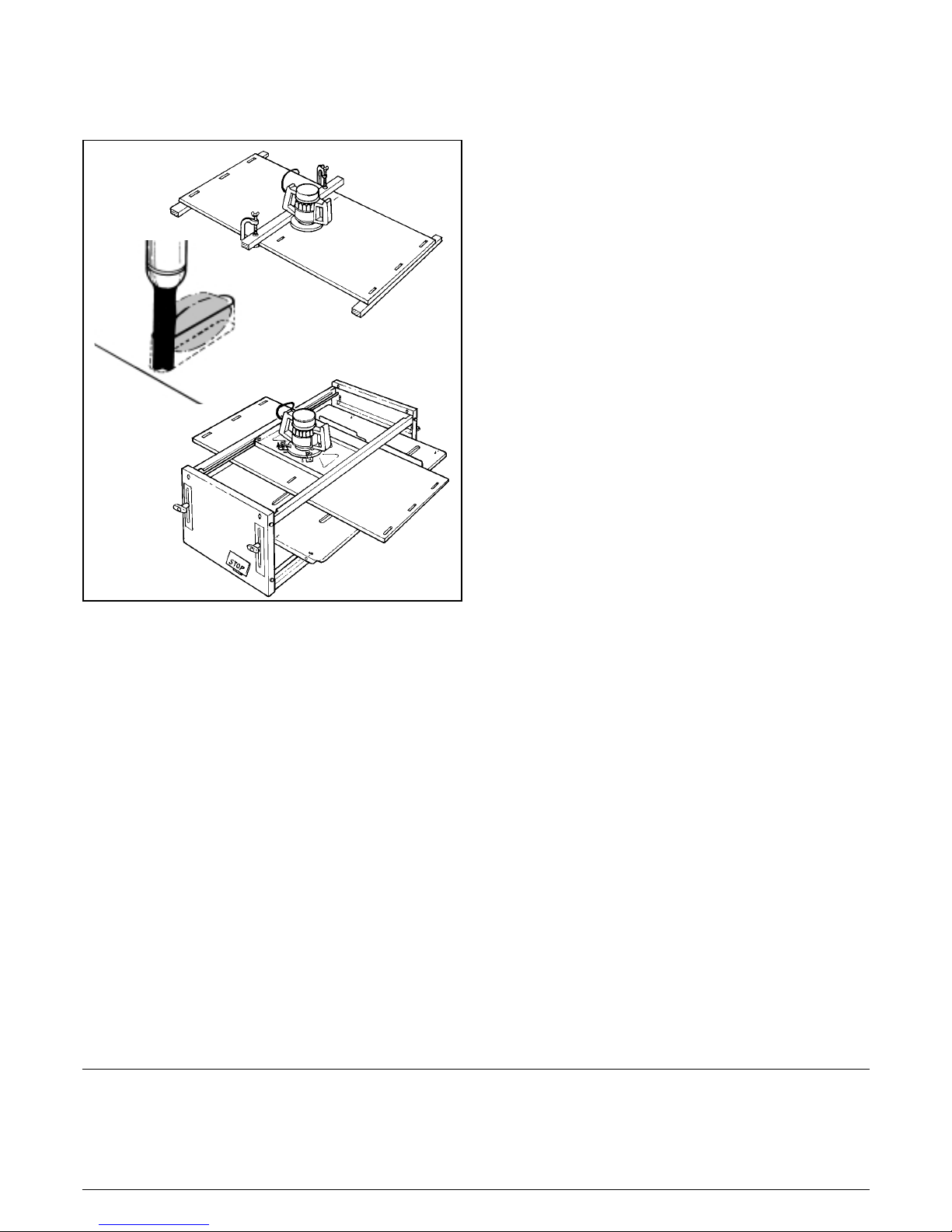
This cutter can be used for cutting mid-panel slots using
the router hand-held against a clamped batten.
Alternatively it can be done in the overhead mode on your
Workcentre using the optional Router Mounting Plate
(AJA150).
With a plunge router, and some practice, you can produce
slots with a curved bottom. However flat-bottomed slots
13mm deep by 40mm long are acceptable, and much
easier.
Biscuit Spacing
The number of biscuits required for particular joints will
depend on the type of material being joined and the loads
which the joint has to carry. As a rule of thumb, use one
biscuit (or row of biscuits) in material up to 20mm thick,
and two biscuits (or rows) in thicker materials, spaced
equally about 1/3rd the way in from either face.
The spacing between the biscuits along edge-to-face
panel joints and bevel joints should be around 150-
200mm. For long edge-to-edge joints, such as for a table-
top in natural timber, around 300mm between biscuits is
generally adequate.
Test Assembly
Test assemble your work before applying the glue to
check alignment and fit. Because the biscuits can move
lengthways in their slots, you can usually true up joints
easily.
The glue faces and the slots should be clean and dry
prior to gluing. Remove any sawdust or shavings by
brushing or blowing.
REPLACEMENT BISCUITS
Triton biscuits are specially shaped to suit the cutter
supplied. Replacement Triton biscuits are available from
your Triton stockist in packs of 50 (BJA050), or 500
(BJA056).
You can use other brands of biscuits, but they are a
different size. These biscuits, commonly called #10 and
#20 biscuits, require elongated slots. Use the reference
lines printed on top of the main body on either side of the
central line. Start at the line marked “20” and move the
wood towards the outside line, in the direction of the
arrow.
The #10 biscuit slots require the depth stops to be
adjusted to reduce the travel of the sliding insert.
GLUES AND GLUE APPLICATION
Good quality water-based adhesives, such as PVA glues,
are the most suitable for biscuit joining because they have
good quality wetting properties, and the moisture makes
the biscuits swell up evenly to tighten the joint. Epoxy and
resorcinol-type adhesives can be used, but we do not
recommend the use of highly viscous glues such as
construction adhesives.
Triton brand Premium Woodworking Adhesive offers
superior bond strength and better sanding and staining
characteristics than most commonly available PVA glues.
Available in 250ml, 500ml and 2.5 litre bottles.
Apply the glue sensibly. It is unnecessary and wasteful to
fill the slots with glue. On the other hand you need
enough glue to fully “wet-out” the sides of the biscuits.
Coat the biscuits with glue and/or paint glue on the walls
of the slots, using a thin spatula, a cotton bud, or a small
paint brush (a #6 artists size is ideal).
The best way to tell if you’re using the right amount of
glue is when you clamp the joint. A fine line of glue should
be squeezed out. Glue liberally dripping out indicates an
excess, and no glue visible means a starved joint.
CARE OF THE CUTTER
Inspect the cutter teeth regularly for chips or bluntness,
and remove accumulated resins from the tips. Have the
cutter professionally sharpened when blunt. When not
fitted to your router the cutter should be stored in its
special housing at the end of the main body to prevent
accidental tooth chipping.
Replacement cutters (BJA038) or cutting discs (BJA039)
can be ordered through your Triton stockist
Fig. 23
Other manuals for BJA 300
1
Table of contents
Other Triton Biscuit Joiner manuals