SteelMax SM-BM-16 User manual

The tools of innovation.
112 Inverness Circle East Suite F Englewood, CO 80112
1–87STEELMAX, FAX 303–690–9172
www.steelmax.com [email protected]
OPERATOR’S MANUAL
S
SM
M-
-B
BM
M-
-1
16
6
BEVELING MACHINE

SM-BM-16
SM-BM-16 Operator’s Manual
2

SM-BM-16
SM-BM-16 Operator’s Manual
3
Contents
1. GENERAL INFORMATION............................................................................................... 4
1.1. Application................................................................................................................. 4
1.2. Technical data............................................................................................................ 4
1.3. Design ....................................................................................................................... 5
1.4. Equipment included ................................................................................................... 6
2. SAFETY PRECAUTIONS.................................................................................................. 7
3. STARTUP AND OPERATION........................................................................................... 9
3.1. Mounting and dismounting of milling head ................................................................. 9
3.2. Adjustment of bevel parameters................................................................................10
3.3. Adjustment of guide for rounding of edges................................................................11
3.4. Preparation...............................................................................................................11
3.5. Usage.......................................................................................................................12
3.6. Replacement of cutting inserts..................................................................................13
3.7. Replacement of roller................................................................................................14
3.8. Replacement of brushes...........................................................................................15
4. ACCESSORIES AND SPARE PARTS.............................................................................16
4.1. Accessories ..............................................................................................................16
4.2. Spare and wearing parts...........................................................................................16
5. EXPLODED DRAWINGS AND PARTS LIST....................................................................17
6. DECLARATION OF CONFORMITY.................................................................................22
7. QUALITY CERTIFICATE..................................................................................................23
8. WARRANTY CARD..........................................................................................................24

SM-BM-16
SM-BM-16 Operator’s Manual
4
1. GENERAL INFORMATION
1.1.Application
The BM-16 Beveling Machine is designed for milling edges of plates and pipes made
of steel, aluminum alloys, brass, or plastics. Depending on used milling head the
machine allows for beveling materials of the minimum thickness of 1.5 mm (0.06’’) at
the angle of 20°, 22.5°, 30°, 37.5°, 45°, 50°, 55°, 60°, or 65° and with the maximum
bevel width of 16 mm (0.63’’). It also allows for rounding edges using the radius of
3, 4, or 5 mm. The minimum diameter of a hole to be machined is 40 mm (1.57’’).
1.2.Technical data
Voltage ~ 220–240 V, 50–60 Hz
~ 110–120 V, 50–60 Hz
Power 2200 W
Rotational speed (without load) 1800–5850 rpm
Protection level IP 20
Protection class
II
Maximum bevel width
b= 16 mm (0.63’’, Figure 1)
Bevel angle (depending on milling head) ß= 20°, 22.5°, 30°, 37.5°, 45°, 50°, 55°,
60°, 65° (Figure 1)
Minimum material thickness for beveling
1.5 mm (0.06’’)
Minimum machining hole diameter 40 mm (1.57’’)
Rounding of edges R3, R4, R5 (Figure 1)
Noise level Above 70 dB
Vibration level 2.3 m/s2(7.5 ft/s2
Category III (PN-90/N-01357)
)
Machine harmful for health. Take
periodic breaks during operation.
Required ambient temperature 0–40°C (34–104°F)
Weight (without milling head) 10 kg (22 lbs)
Figure 1. Bevel dimensions

SM-BM-16
SM-BM-16 Operator’s Manual
5
1.3.Design
Figure 2. BM-16 beveling machine design
rotational speed
adjusting dial
handle
handle
spindle lock button
switch lock
ON/OFF switch
guide
clamping screw
milling head
guiding roller
sleeve
585 mm (23.0’’)
238 mm (9.4’’)
156 mm (6.1’’)

SM-BM-16
SM-BM-16 Operator’s Manual
6
1.4.Equipment included
The BM-16 Beveling Machine is supplied in a metal box. The included equipment
consists of:
•beveling machine (without milling head) – 1 unit
•metal box – 1 unit
•14 mm hex wrench – 1 unit
•
5 mm hex wrench
– 1 unit
•32 mm flat wrench – 1 unit
•Operator’s Manual – 1 unit

SM-BM-16
SM-BM-16 Operator’s Manual
7
2. SAFETY PRECAUTIONS
1. Before starting, read this Operator’s Manual and complete proper occupational
safety and health training.
2. Machine must be used only in applications specified in this Operator’s Manual.
3. Machine must be complete and all parts must be genuine and fully operational.
4. Power supply specifications must conform to those specified on rating plate.
5. Never carry machine by cord or yank it to disconnect plug from socket. It can
cause power cord to break and result in electric shock.
6. Untrained bystanders must not be present near machine.
7. Before starting, check condition of machine and electrical installation, including
power cord, plug, control components, and milling tools.
8. Keep machine dry. Exposing it to rain, snow, or frost is prohibited.
9. Keep work area well lit, clean, and free of obstacles.
10. Never use machine near flammable fluids or gases, nor in explosive environments.
11. Never use dull or damaged tools.
12. Use only tools recommended by manufacturer and specified in Operator’s Manual.
13. Mount cutting inserts and milling head securely. Remove adjusting keys and
wrenches from work area before connecting plug to power socket.
14. Never use machine in upside down position with milling head facing up.
15. If cutting edge of insert is worn out, rotate insert in socket by 90° or 180° or, if all
edges are worn out, replace with new insert specified in Operator’s Manual.
16. Before every use, inspect machine to ensure it is not damaged. Check whether
any part is cracked or improperly fitted. Make sure to maintain proper conditions
that may affect machine operation.
17. Always use eye and hearing protection, non-skid footwear, and protective clothing
during operation. Do not wear loose clothing.
18. Using spindle lock button during operation is prohibited.
19. Do not touch moving parts or metal chips formed during milling. Prevent objects
from being caught in moving parts.
20. After every use, remove metal chips from machine, particularly from milling head.
Never remove metal chips with bare hands.
21. Maintain machine and tools with care. Cover steel parts with thin grease layer to
protect them against rust when not in use for a longer period.

SM-BM-16
SM-BM-16 Operator’s Manual
8
22. Perform maintenance and parts replacements only with power cord unplugged
from power socket.
23. Perform repairs only in service center appointed by seller.
24. If machine falls on hard surface, from height, is wet, or has other damage that
could affect technical state of machine, stop operation and immediately send
machine to service center for inspection.
25. Remove from worksite and store in an isolated and dry location when not in use.

SM-BM-16
SM-BM-16 Operator’s Manual
9
3. STARTUP AND OPERATION
3.1.Mounting and dismounting of milling head
Unplug the power cord from power socket. To mount the milling head (Figure 3a),
place it on the spindle (1), press the spindle lock button 2, and tighten the head using
14 mm hex wrench (3). Remove the nut and assemble the roller with the pivot (4),
placing a few washers under the roller to keep a little distance between the roller and
cutting inserts (5). Place all unused washers between the roller and pivot. Place the
roller (6), press the button 2, and tighten with 5 mm hex wrench (7).
Figure 3. Method of mounting (a) and dismounting (b) of milling head
To dismount the head (Figure 3b), loosen the clamping screw (8), then unscrew
the sleeve (9) and take it out (10). Next, press the button 2, unscrew the roller using
All safety precautions must be closely observed.
b)
13
9
8
12
15
14
1
11
2
1
3
6
7
a)
4
5
SM-BM-16
SM-BM-16 Operator’s Manual
10
5 mm hex wrench (11) and dismount (12). Lock the spindle with 32 mm flat wrench
(13), after which unscrew the head using 14 mm hex wrench (14)and dismount (15).
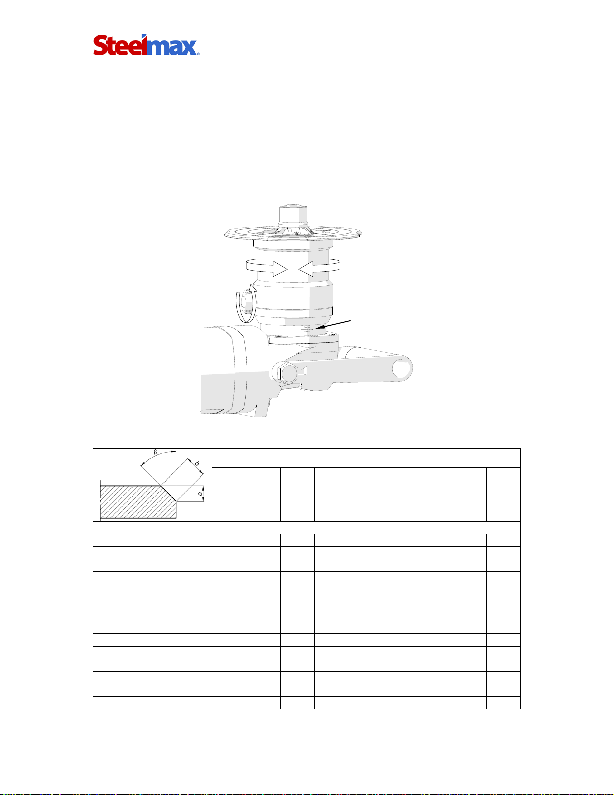
3.2.Adjustment of bevel parameters
Unplug the power cord from power socket. Then, loosen the clamping screw (1,
Figure 4), rotate the sleeve (2) in a way that the pitch 3shows the required bevel
height „a” (Table 1), and re-tighten the screw afterward.
Figure 4. Method of adjusting the bevel parameters
Milling head
20° 22.5° 30° 37.5° 45° 50° 55° 60° 65°
Height ”a”
[mm]
Width ”b”
[mm]
1
1.1
1.1
1.2
1.3
1.4
1.6
1.7
2.0
2.4
2 2.1 2.2 2.3 2.5 2.8 3.1 3.5 4.0 4.7
3 3.2 3.2 3.5 3.8 4.2 4.7 5.2 6.0 7.1
4 4.3 4.3 4.6 5.0 5.7 6.2 7.0 8.0 9.5
5
5.3
5.4
5.8
6.3
7.1
7.8
8.7
10.0
11.8
6 6.4 6.5 6.9 7.6 8.5 9.3 10.5 12.0 14.2
7 7.4 7.6 8.1 8.8 9.9 10.9 12.2 14.0
8 8.5 8.7 9.2 10.1 11.3 12.4 13.9 16.0
9
9.6
9.7
10.4
11.3
12.7
14.0
15.7
10 10.6 10.8 11.5 12.6 14.1 15.6
11 11.7 11.9 12.7 13.9 15.6
11.5 12.2 12.4 13.3 14.5 16.3
12
12.8
13.0
13.9
15.1
13 13.8 14.1 15.0
Table 1. Relation between bevel width and height of the available milling heads
1
2
3

SM-BM-16
SM-BM-16 Operator’s Manual
11
3.3.Adjustment of guide for rounding of edges
Unplug the power cord from power socket, after which in the manner described
before loosen the clamping screw and rotate the sleeve to set the guide as shown in
Figure 5. Then, after leveling the surface 1with the radial cutting edge 2,re-tighten
the clamping screw. Round a test edge and, if necessary, readjust the guide position.
Figure 5. Guide adjusted for rounding of edges
3.4.Preparation
Mount a milling head with cutting inserts and set the required bevel parameters.
Then, using the rotational speed adjusting dial, set the speed corresponding to the
type of the working material (Table 2).
Material type Rotational speed
Aluminum, brass, plastics setting 6
(5850 rpm)
Structural steel of standard quality, quality steel settings 3–5
(3100–4500 rpm)
Table 2. Recommended rotational speeds
The speed adjusting dial allows for continuous control of the rotational speed in
the range of 1800–5850 rpm (settings 1–6). The relations between the setting and
speed are: setting 1– 1800 rpm, 2– 2400 rpm, 3– 3100 rpm, 4– 3800 rpm, 5–
4500 rpm, 6– 5850 rpm.
When using structural steel of a standard quality or quality steel, set the speed to
setting 4and decrease it if intensive sparking occurs during operation.
2
1

SM-BM-16
SM-BM-16 Operator’s Manual
12
3.5.Usage
Plug the power cord into power socket and place the machine on the left side of the
working material in the manner shown in Figure 6. The milling head must not touch
the working edge. The working material must be stable and well fixed.
Figure 6. Machine placed on plate and proper feed direction
To start the motor, press the switch lock and the ON/OFF switch, and, with the
ON/OFF switch pressed, release the lock. Wait several seconds until the machine
reaches the required rotational speed, press the machine to the working surface
using both hands, and slowly slide toward the edge until the tool starts to cut the
steel. Operate according to the counter-rotation, by sliding the machine from left to
right. The direction of the milling head rotation is indicated by the arrow on the guide.
Begin with accomplishing small bevels (3–4 mm, 0.12–0.16’’) and increase the
bevel width with gaining experience. Bevel in at least two or three passes. The bevel
width should be set to a value which will allow for the feed of 1 meter per minute
without significant effort.
If the machine becomes overloaded, e.g. when the bevel width is too large for the
material being machined or when the cutting inserts are dull, the motor will
automatically stop. However, prevent the motor from overloading by machining hard
materials in multiple passes and by replacing the inserts before they become dull.
Additionally, take periodic breaks during operation and keep the ventilation slots
clean to prevent the motor from overheating because this can lead to damage of the
windings.
Once the work is finished, turn off the motor by releasing the ON/OFF switch, wait
until the rotation stops, and unplug the power cord from power socket.
feed direction
switch lock
ON/OFF switch
SM-BM-16
SM-BM-16 Operator’s Manual
13
3.6.Replacement of cutting inserts
Unplug the power cord from power socket and, to achieve better access to the head,
loosen the clamping screw (1, Figure 7) and maximally lower the sleeve by rotating it
clockwise (2). Then, unscrew the screw (3) using the screwdriver supplied with the
milling head, and take out the cutting insert (4). Clean the socket and place the
rotated insert again or replace with a new one if all four edges are worn out. Then,
push and tighten the insert.
Before replacement of cutting inserts for rounding of edges, press the spindle lock
button 5and loosen the guiding roller with 5 mm hex wrench (6).
Figure 7. Method of replacing the cutting inserts
Clean the threads once a week and, if necessary, grease the mounting screws
for inserts using an agent that will prevent the bolts from blocking (e.g. copper paste).
3
1
2
4
6
5

SM-BM-16
SM-BM-16 Operator’s Manual
14
3.7.Replacement of roller
Unplug the power cord from power socket. Then, place the machine in the manner
shown in Figure 8, press the spindle lock button 1, and unscrew the roller using 5 mm
hex wrench (2).
Remove the nut and assemble the new roller with the pivot (3), placing a few
washers under the roller to keep a little distance between the roller and cutting inserts
(4). Place all unused washers between the roller and pivot, after which press the
button 1, and screw in the new roller with 5 mm hex wrench (2).
Figure 8. Method of replacing the roller
1
2
3
4

SM-BM-16
SM-BM-16 Operator’s Manual
15
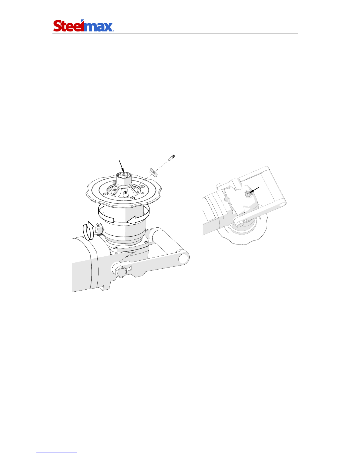
3.8.Replacement of brushes
Check condition of the carbon brushes every 200 operational hours. If their length is
less than 10 mm (0.4’’), replace them with new ones. To do this, unplug the power
cord from power socket, unscrew the cap, and take out the brush (Figure 9). Proceed
as described also for the second brush located on the opposite side of the motor.
To mount brushes, proceed in reverse order. After the replacement, run the motor
without load for 20 minutes.
Figure 9. Method of replacing the brushes

SM-BM-16
SM-BM-16 Operator’s Manual
16
4. ACCESSORIES AND SPARE PARTS
4.1.Accessories
Part number Name
GLW-000011 Milling head for rounding
GLW-000005 Milling head 30°
GLW-000006 Milling head 45°
GLW-000007 Milling head 60°
GLW-000008 Milling head 55°
GLW-000009 Milling head 37.5°
GLW-000010 Milling head 22.5°
GLW-000016 Milling head 20°
GLW-000017 Milling head 50°
GLW-000018 Milling head 65°
SRB-000289 Mounting screw for rounding insert
SRB-000290 Mounting screw for beveling insert
PLY-000159 Rounding insert R3
PLY-000160 Rounding insert R4
PLY-000161 Rounding insert R5
PLY-000162 Beveling insert for steel
PLY-000195 Beveling insert for aluminum
4.2.Spare and wearing parts
Part number Name
RLK-0509-04-00-00-0 Guiding roller
SCZ-000031 Carbon brush for 110 V
SCZ-000030 Carbon brush for 230 V
KLC-000027 32 mm one-sided flat wrench
KLC-000008 5 mm hex wrench
KLC-000029 14 mm hex wrench
KLC-000028 T15 torx screwdriver
SMR-000005 Grease for screws (5 g, 0.17 oz)

SM-BM-16
SM-BM-16 Operator’s Manual
17
5. EXPLODED DRAWINGS AND PARTS LIST
20
5
25
26
1
2
9
11
21
12
10
24
7
16
8
28
32
17
31
3
29
33
18
27
32
22
31
4
15
30
13
6
19
23

SM-BM-16
SM-BM-16 Operator’s Manual
18
ITEM
PART NUMBER
DESCRIPTION
Q-TY
1
TLJ-0427-01-03-00-1
SLIDING SLEEVE
1
2
PRW-0427-01-05-00-0
GUIDE
1
3
TLJ-0509-01-01-00-0
SPINDLE SLEEVE
1
4
RLK-0509-04-00-00-0
GUIDING ROLLER ASSY
1
5
WRZ-0509-01-02-00-0
SPINDLE
1
6
TLJ-0509-01-03-00-0
DISTANCE SLEEVE
1
7
KOL-0509-01-04-00-0
BEVEL GEAR z=53
1
8
NKR-0509-01-05-00-0
LOCKING NUT
1
9
OSL-0509-01-06-00-0
BEARING COVER
1
10
PDK-0509-02-00-00-0
DISTANCE WASHER 0.2
1
11
PDK-0509-02-00-00-1
DISTANCE WASHER 0.3
1
12
NPD-000012
MOTOR ASSY 230V
1
12
NPD-000013
MOTOR ASSY 110V
1
13
PRS-000019
EXTERNAL RETAINING RING 28z
1
14
KLC-0427-11-01-00-0
32 MM SPECIAL WRENCH
1
15
PRS-000285
SEAL A-RING 28x42x7
1
16
PRS-000286
SEAL O-RING 80x3
1
17
PRS-000274
SEAL O-RING 72x3
1
18
PKT-000037
HAND LEVER
1
19
WKR-000134
HEX SOCKET COUNTERSUNK HEAD SCREW M5x12
4
20
WPS-000010
KEY 5x5x14
1
21
LOZ-000049
BALL BEARING 30x55x13
1
22
SRB-000086
HEX SOCKET BOLT M5x20
4
23
PRS-000021
EXTERNAL RETAINING RING 30z
1
24 PRS-000033 INTERNAL RETAINING RING 55w 1
25
RLK-0427-14-02-00-1
ROLLER
1
26
SWR-0509-04-01-00-0
ROLLER PIVOT
1
27
TLJ-0509-04-02-00-0
ROLLER SLEEVE
1
28
NKR-000018
HEX. NUT M6
1
29
PRS-000003
EXTERNAL RETAINING RING 12z
1
30
PRS-000018
INTERNAL RETAINING RING 28w
1
31
PDK-000174
WASHER 8x14x0.1
3
32
PDK-000010
WASHER 8x14x0.5
4
33
LOZ-000038
BALL BEARING 12x28x8
2
34*
KLC-000008
5 MM HEX. WRENCH
1
35*
KLC-000029
14 MM HEX. WRENCH
1
36*
GLW-000005
MILLING HEAD 30°
1
37*
GLW-000006
MILLING HEAD 45°
1
38*
GLW-000007
MILLING HEAD 60°
1
39*
GLW-000008
MILLING HEAD 55°
1
40*
GLW-000009
MILLING HEAD 37.5°
1
41*
GLW-000010
MILLING HEAD 22.5°
1
42*
GLW-000016
MILLING HEAD 20°
1
43*
GLW-000017
MILLING HEAD 50°
1
44*
GLW-000018
MILLING HEAD 65°
1
45*
PLY-000162
BEVELING INSERT FOR STEEL
5
46*
PLY-000195
BEVELING INSERT FOR ALUMINIUM
5
47*
SRB-000290
MOUNTING SCREW FOR BEVELING INSERT
5
48*
GLW-000011
MILLING HEAD FOR ROUNDING
1
49*
PLY-000159
ROUNDING INSERT R3
4
50*
PLY-000160
ROUNDING INSERT R4
4
51*
PLY-000161
ROUNDING INSERT R5
4
52*
SRB-000289
MOUNTING SCREW FOR ROUNDING INSERT
4
* not shown on the drawing

SM-BM-16
SM-BM-16 Operator’s Manual
19

SM-BM-16
SM-BM-16 Operator’s Manual
20
NPD-000011 MOTOR ASSY 110V (US)
NPD-000012 MOTOR ASSY 230V
NPD-000013 MOTOR ASSY 110V
ITEM
PART NUMBER
DESCRIPTION
Q-TY
4 LOZ-000133 SLIDE SLEEVE HK 1512 1
5 KRP-000070 GEAR BODY 1
6 SRB-000338 HEAD SCREW TX25 M5x45 4
7
PRS-000291
SEALING RING 18W
1
8 SPR-000050 SPRING 1
9 SWR-000002 SPINDLE LOCK PIVOT 1
10 RKJ-000059 FRONT HANDLE COMPLETE 1
11
RKJ-000060
FRONT HANDLE
1
12 SRB-000341 FULLY THREADED HEX CAP SCREW M14x25 2
13 NKR-000145 NUT M8x1 DIN 936 1
14 KOL-000089 BEVEL GEAR MZ 1.5x12 1
15
DYS-000009
DISTANCE
1
16 USZ-000044 SEALING 1
17 LOZ-000135 BALL BEARING 6202-2RSLTN9/LHT23 1
18 USZ-000045 SEALING 6003JV 1
19
PKR-000051
COVER
1
20 PDK-000189 WASHER NL8 1
21 WKR-000433 HEX SOCKET COUNTERSUNK HEAD SCREW M5x16 2
22 WNT-000009 FAN 1
23 WRN-000045 ROTOR 230V 1
23 WRN-000046 ROTOR 110V 1
24 LOZ-000136 BALL BEARING 6001-2RSLTN9/C3LH 1
25 PRS-000292 MAGNETIC RING 1
26
LOZ-000137
BEARING
1
27 OSL-000187 STATOR GUARD 230/CEE 1
28 SRB-000343 SCREW KT-KT 5x74 2
29 STN-000032 STATOR 230V 1
29
STN-000033
STATOR 110V
1
30 OBD-000035 STATOR HOUSING 230V 1
30 OBD-000036 STATOR HOUSING 110V 1
31 SCT-000010 BRUSH HOLDER 230V 2
31
SCT-000011
BRUSH HOLDER 110V
2
32 SCZ-000030 BRUSH 230V 2
32 SCZ-000031 BRUSH 110V 2
33 PKR-000046 BRUSH HOLDER COVER 2
34
PKR-000047
HANDLE COVER SB
1
35 ZSP-000014 ROTATIONAL SPEED CONTROLLER UNIT 230V 1
35 ZSP-000015 ROTATIONAL SPEED CONTROLLER UNIT 110V 1
36 PKR-000048 CONTROLLER BODY COVER 1
37
PDK-000193
INSULATION WASHER
1
38 OSL-000189 WIRE SHIELD GF 1
39 KRP-000075 HANDLE BODY 1
40 SRB-000343 SCREW KT-KT 5x74 4
41
SRB-000344
SCREW KT-KT 4x30
1
42 SRB-000345 SCREW KT-KT 4x20 1
43 TLJ-000108 LOCK SLEEVE 1
44 BLD-000016 SWITCH LOCK 1
45
SPR-000052
SPRING
1
Other manuals for SM-BM-16
1
Table of contents
Other SteelMax Power Tools manuals


Popular Power Tools manuals by other brands


stayer
stayer SUH2000E operating instructions

Power Team
Power Team C12-HTR series Operating instructions and parts list

Bräunlich
Bräunlich GALLUNOPTIMAL GOHLK300 quick start guide

Sioux Tools
Sioux Tools TP9A Series Instructions-parts list

VONROC
VONROC S_RS501DC Original instructions

DUROFIX
DUROFIX G12 Series Product information manual


