5
Bassbreaker™ 18/30
(This is the model name for warranty claims)
A footswitch or the top panel channel select switch
is used to accuate relay K1 to select the output of
the appropriate tone stack for the 30W channel
VOLUME, BASS, MIDDLE, and TREBLE) or the
18W channel (VOLUME, TONE). The footswitch or
top panel or top panel channel select switch also
selects the variable headroom of the power
amplifier.
V2 is a combination voltage amplifier (V2A) and
split load phase inverter (V2B) that feeds the power
amp EL84 output tubes.
POWER AMPLIFIER
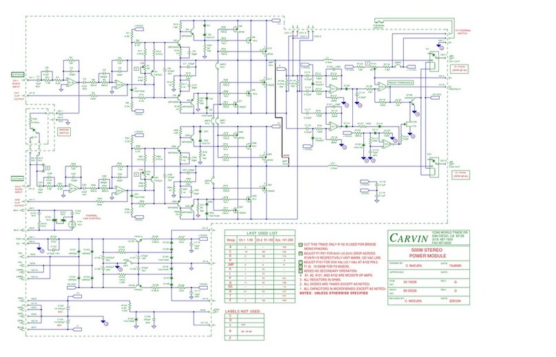
The output of the selected tone control feeds V2A
which is a tone stack recovery stage while V2B
functions as a “split load” phase inverter. The plate
and cathode of phase inverter V2B feed the grids of
output tubes V3 –V6 which are arranged as a
push-pull quad. The plates of V3 –V6 feed the
primary of output transformer T1.
The secondary of T1 provides 16, 8, or 4 ohms
output by way of IMPEDANCE SELECT switch
S201 on the back panel. The IMPEDANCE
SELECT switch feeds J5 MAIN SPEAKER jack.
The tip shunt of J5 goes to the internal 16 ohm
speaker load in the cabinet (two 12”, 8 ohm
speakers wired in series). The EXTENSION
SPEAKER jack J4 is wired in parallel with MAIN
SPEAKER jack.
The internal speakers are driven via the tip shunt of
the MAIN SPEAKER jack J5. (The IMPEDANCE
SELECT switch should always be set to 16 ohms
when the internal speakers are used exclusively.)
Plugging a speaker into the MAIN SPEAKER jack
disconnects the internal speakers so that only the
speaker plugged into the MAIN SPEAKER jack is
driven. If a speaker is plugged into the EXTENSION
SPEAKER jack J4 instead of the MAIN SPEAKER
jack, the external speaker will be put in parallel with
the internal speakers. Plugging a speaker into the
MAIN SPEAKER and EXTERNAL SPEAKER jacks
will disconnect the internal speakers, and put the
speakers plugged into the MAIN SPEAKER and
EXTENSION SPEAKER jacks in parallel.
Resistor R37 10 Kohm 1/2W is connected between
the 16 ohm output of T1 and the tip of J3 (POST
POWER AMP LINE OUT). Components R38 (82
Ohms) and C16 (220pF) are connected from the tip
of J3 to ground. The following components R61,
R39, and C17 are connected from the shunt of J3 to
ground to provide a low level replica of the signal at
the output of the power transformer.
POWER SUPPLY
The power supply circuitry is located on the large
PCA that is between the control PCA and tube PCA.
Certain aspects of the power supply are not typical
of power supplies found in other Fender tube
amplifiers. It has a regulated selectable voltage
screen supply for the output tubes, and a selectable
cathode bias resistor network that tracks the screen
supply. The screen supply voltage is controlled by a
footswitch or by the top panel channel select push
button control to select an amplifier output power of
18 watts or 30 watts. The cathode bias resistor
value tracks the screen supply to properly self-bias
the output tubes and maintain proper idle current.
The high voltage red-red secondary winding of T2 is
rectified by a full wave bridge and is filtered by C25
to provide the high voltage DC plate supply for V3,
V4, V5, and V6 (B+). It is further R-C filtered to
provide plate supplies for V2B (Y), V2A, and V1 (X).
The B+ supply is also used to feed the input to the
screen supply for V3, V4, V5 and V6.
The brown-brown/brown-yellow secondary winding
of T2 is rectified by a full wave bridge and filtered by
C30 to provide + 24 VDC. This feeds regulator U7
to provide a regulated +15VDC supply to power
the control circuit to select screen voltage
the control circuit to select cathode resistor
network values.
the 12V tone stack selection relay (K1)
DC filament voltage for tubes V1 and V2.
The green-green secondary winding of T2 provides
AC power for the filaments of V3, V4, V5, and V6.
As stated earlier, the B+ supply from the red-red
winding also feeds the input to the selectable-
voltage screen (Z) supply. The screen supply
