FENDT FORMER 12545 PRO User manual

FORMER
AGCO GmbH ·Fellastraße 1-3 ·D-90537 Feucht
© AGCO
07.2019
12545 PRO
FCL 025001
Operator's Manual
Rotary rake
FENDT is a worldwide brand of AGCO
Original Operator's Manual
FEL16917904_EN02
English


FORMER 12545 PRO 1
This Operator's Manual describes all equipment and variants, including optional equipment
that is not supplied in the standard scope of delivery.
Customers cannot derive any claims regarding the equipment of machines that have been
supplied or are to be supplied on the basis of this description.
Our machines undergo continuous further development. All technical details and illustrations
in this Operator's Manual are therefore non-binding and we reserve the right to make
changes.
Legal notice
Document type: Operator's Manual
Product: Rotary rake
Model: FORMER 12545 PRO
Language: EN – English
Publication status: 07 2019
Address: AGCO GmbH
Fellastraße 1-3
90537 Feucht
Germany
© Copyright by AGCO GmbH
All parts of this documentation are protected by copyright.
Any use beyond that permitted by copyright law requires the written consent of AGCO
GmbH. This applies in particular to the reproduction, distribution and translation of this docu-
mentation or parts thereof and for the storage and processing of the content with electronic
data processing systems.

2 FORMER 12545 PRO
Contents
1.1Warranty and liability 5
1.2Conventions 5
1.2.1Illustrations 5
1.2.2Pictograms used 5
1.2.3Text symbols 5
1.2.4Abbreviations 5
1.3Other applicable documentation 5
1.4Storage of documentation 6
1.5Applicability of the Operator's Manual 6
1.6Sign plate and serial number 6
1.7EU Declaration of Conformity 7
2.1Intended use 8
2.2Reasonably foreseeable misuse 8
2.3User qualifications 8
2.4Warning notices 8
2.4.1Warning notices in the Operator's Manual 8
2.4.2Warning notices on the machine 9
2.5Safety instructions 10
2.5.1Operating and maintenance personnel 10
2.5.2Protective work wear 11
2.5.3Personal protective equipment 11
2.5.4Preparing the machine for use 11
2.5.5Coupling/uncoupling the machine to/from the tractor 11
2.5.6Machine operation 11
2.5.7Driving on public roads and lanes 11
2.5.8Maintenance work 12
2.5.9Working with hydraulics 12
2.5.10Work in the vicinity of high-voltage power lines 12
2.5.11Unauthorized modifications or alterations 12
2.5.12What to do in an emergency 12
2.5.13Fire prevention 12
3.1Product features 14
3.2Machine positions 14
3.2.1Transport position 14
3.2.2Working position 14
3.2.3Headland position 14
3.2.4Parking position 14
3.3Notices on the machine 14
3.4Machine components 15

FORMER 12545 PRO 3
4.1Display layout 16
4.2General buttons 17
4.3Menus 18
4.3.1Menu structure 18
4.3.2"Main menu" 18
4.3.3"Transport" menu 19
4.3.4"Lifting/Lowering" menu 21
4.3.5"Working Setup" menu 24
4.3.6"On-Board Computer" menu 26
4.3.7"User Setup" menu 27
4.3.8"Manual Operation" menu 28
4.3.9"Headland position" menu 30
4.3.10"Calibrations" menu 31
4.3.11"Diagnostics" menu 32
4.3.12"Factory Settings" menu 33
4.4Error messages 34
5.1Machine data 36
5.2Tires 36
5.3Noise information 37
5.4Axle loads, gross weight and minimum ballast required 38
6.1Assembling the machine 39
6.2Adjusting the transmission shaft 39
7.1Attachment to the tractor 41
7.1.1Start-up 41
7.1.2Coupling the machine 41
7.1.3Fitting the transmission shaft 42
7.1.4Connect the hydraulics 42
7.1.5Connect the lighting 43
7.1.6Connecting the ISOBUS 44
7.1.7Connect the air pressure brake 44
7.1.8Releasing the parking brake 44
7.2Road travel 44
7.3Switching the machine to working position 45
7.4Using the machine 46
7.4.1Turning at the end of the field 47
7.5Switching the machine to transport position 48
7.6Machine storage 49
7.7Settings 51
7.7.1Adjusting the swath width 51
7.7.2Set working width 51
7.7.3Adjusting working height 52

4 FORMER 12545 PRO
7.7.4Adjusting the height of the swath former 52
7.7.5Adjusting the swath formation 53
7.7.6Adjusting the lateral inclination 53
7.7.7Adjusting the longitudinal inclination 55
7.7.8Adjusting the sequential control 55
7.7.9Setting the two-rotor operation mode 56
7.7.10Setting individual rotor operation mode 56
9.1After hitting an obstacle 60
9.2Emergency operation 60
9.2.1Lifting rotors into the transport position 60
9.2.2Lowering rotors into working position 61
9.2.3Lifting rotors into the headland position 61
9.2.4Setting the working width in emergency operation 61
9.2.5Setting the swath width in emergency operation 61
9.2.6Setting the working height in emergency operation 61
10.1Maintenance intervals 62
10.2Cleaning 63
10.3Tightening torques for nuts and bolts 63
10.4Decals 63
10.5Transmission shaft maintenance 64
10.6Servicing the hydraulics 64
10.7Brake system maintenance 67
10.7.1Checking the thickness of the brake pads 67
10.7.2Tightening brake cylinders 67
10.7.3Drain the water from the compressed air reservoir 68
10.8Gearbox maintenance 68
10.8.1Checking gearbox GT-30 oil level 68
10.8.2Checking gearbox GT-40 oil level 68
10.8.3Checking transfer gearbox oil level 68
10.9Tire maintenance 69
10.9.1Changing wheels 69
10.9.2Tire pressure 69
10.10Lubrication instructions 69
11.1Storage 71
11.2Disposal 71

Introduction
FORMER 12545 PRO 5
Introduction
These operating instructions for the
FORMER 12545 PRO rotor rake contain
detailed instructions and information re-
garding safe use, maintenance, special
precautions and any special equipment that
is available.
As a result of continuous further develop-
ment of the machines, all technical data, il-
lustrations and photos in this Operator's
Manual are non-binding and we reserve the
right to make changes. No alteration ser-
vice is offered for this Operator's Manual.
Read the Operator's Manual carefully be-
fore switching on or using the machine for
the first time. The Operator's Manual helps
familiarize the user with the machine's op-
eration and provides details about function
and maintenance.
The Operator's Manual must be available
to the user at all times and must be within
reach, close to the machine.
The information regarding maintenance
and operational safety that is provided in
the Operator's Manual must be observed
and complied with.
In order to visualize it better, safety equip-
ment and covers have been removed or
opened in some of the illustrations or pho-
tos featured in this Operator's Manual.
1.1 Warranty and liability
The “General terms and conditions of sales
and delivery” of the manufacturer always
apply. These are made available to the op-
erator on the date of conclusion of the con-
tract at the latest.
1.2 Conventions
The following conventions apply to this Op-
erator's Manual.
1.2.1 Illustrations
The illustration comes first, followed by the
text. In-text references to items in the illus-
trations always refer to the previous illustra-
tion.
1.2.2 Pictograms used
Pictograms are used to highlight passages
relevant to safety or hazardous areas on
the machine.
Pictogram Explanation
Warning symbols warn
against dangers and indicate
warning notices.
Pictograms in combination
with the warning triangle indi-
cate hazardous areas on the
machine (e.g. crushing haz-
ards).
1.2.3 Text symbols
Highlight sym-
bol
Meaning
Instruction or prompt for the
user to carry out a particular
action in the specified order
Unordered list for a clearer
presentation of contents
1. Numbered list, the order of
which must be maintained
(1) Reference to an item num-
ber in an illustration
1.2.4 Abbreviations
Abbrevia-
tion
Meaning
SA Single-acting
DA Double-acting
CAT Category
1.3 Other applicable documen-
tation
When operating the FORMER 12545 PRO
rotary rake, observe all Operator's Manuals
that accompany other components of your
rotary rake.
Other applicable documentation includes:
Operator's Manual for the relevant
transmission shaft.
Introduction
6 FORMER 12545 PRO
1.4 Storage of documentation
Keep this Operator's Manual and all other
supplied documentation in the document
storage box so that they are available when
required.
1.5 Applicability of the Opera-
tor's Manual
This Operator's Manual applies exclusively
to the FORMER 12545 PRO rotary rake,
starting from the serial number specified on
the back of this manual. The serial number
of your rotary rake can be found in the ve-
hicle identification number (VIN) on the
sign plate.
The FORMER 12545 PRO DB rotary rake
is also referred to as "the machine" in the
following sections.
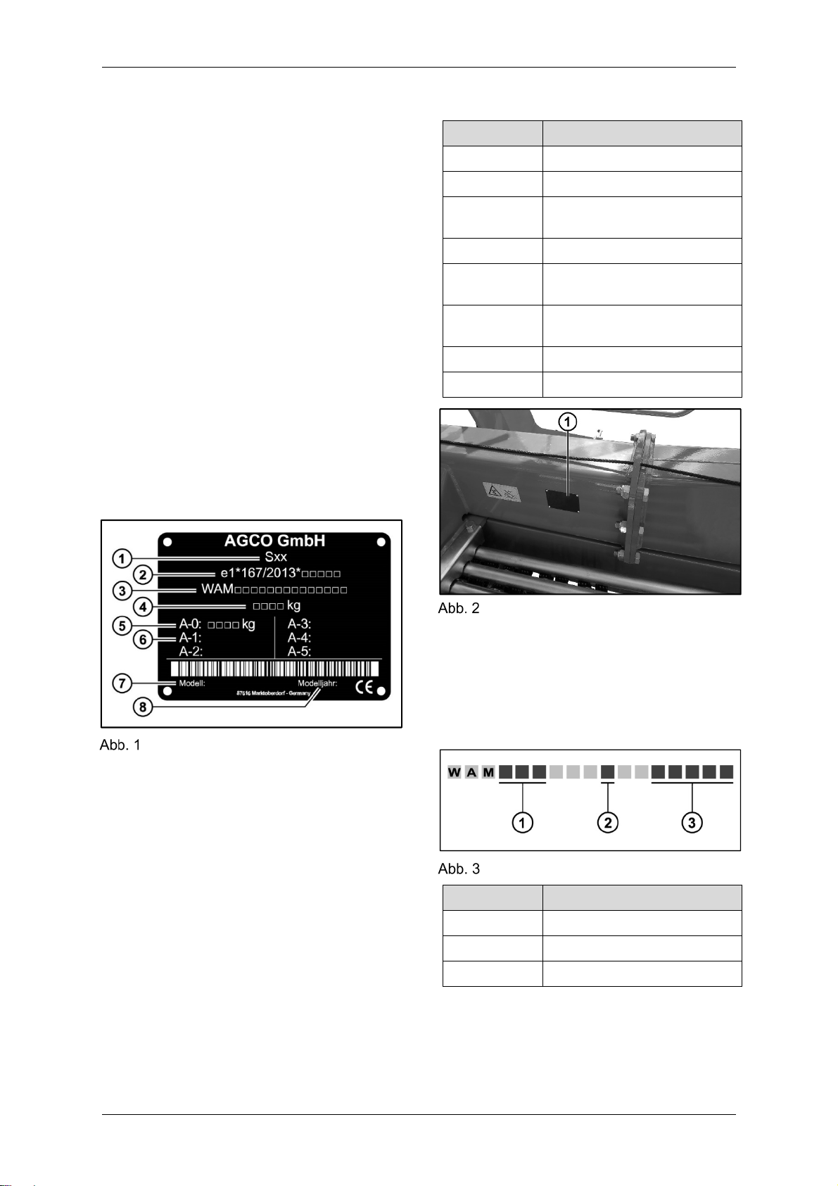
1.6 Sign plate and serial num-
ber
Sign plate
The sign plate includes the following infor-
mation:
Number Information
1 Vehicle class
2 EU type approval number
3 Vehicle identification number
(VIN)
4 Permissible overall weight
5 A-0: Permissible drawbar
load
6 A-1: Permissible axle load,
1st axle
7 Model
8 Model year
Sign plate on the frame
The sign plate (1) is riveted to the frame. It
displays the vehicle identification number
(VIN). The VIN is also stamped on the
frame.
The VIN contains the serial number of the
machine.
FIN/VIN
Number Information
1 Alphabetic code
2 Year of manufacture, coded
3 Consecutive number

Introduction
FORMER 12545 PRO 7
1.7 EU Declaration of Conformity
Manufacturer
AGCO GmbH
Johann Georg Fendt Straße 4
87616 Marktoberdorf
Germany
Product
Designation: Rotary rake
Type: RE
Model: FORMER 12545 PRO
The machine meets the relevant provisions of the following directives:
Machinery Directive 2006/42/EC
EMC Directive 2004/108/EC
The following harmonized standards have been applied:
DIN EN ISO 12100:2011
DIN EN ISO 4254-1:2011
DIN EN ISO 4254-10:2010
The following person is authorized to compile the technical documentation.
Lead Homologation Green Harvesting
Fellastraße 1-3
90537 Feucht
Germany
Marktoberdorf, 2019-07-01 Dr. H. Reiter (Managing Director)

Safety
8 FORMER 12545 PRO
Safety
2.1 Intended use
The rotary rake is used to rake together cut
stalks lying on the ground into a centrally
deposited swath. To do so, the machine
must be in the working position. This ma-
chine has been constructed exclusively for
normal use in agricultural or similar tasks.
Any other type of use is considered unau-
thorized. The manufacturer accepts no re-
sponsibility for any damage caused by im-
proper use. The user alone is responsible
for this.
"Proper use" includes:
Observing all of the information on how
to use the machine in the Operator's
Manual
Taking all warnings into account
Carrying out all inspections and mainte-
nance work as instructed when they are
due
2.2 Reasonably foreseeable
misuse
Examples of reasonably foreseeable mis-
use that may consequently pose a hazard
for the user, third parties or for the machine
during all modes of operation are:
Not using the machine in accordance
with the proper use
Operating the machine without observ-
ing the operational parameters de-
scribed in the machine data table
Changing the machine, along with at-
tachments and modifications, without
previously consulting the manufacturer
Not using the machine as instructed in
the Operator's Manual, with regard to
safety instructions, installation, opera-
tion and maintenance and repair
Bypassing or decommissioning the ma-
chine's protective and safety equipment
Using an obviously damaged or faulty
machine
Repairing, cleaning or servicing the ma-
chine without switching it off
2.3 User qualifications
This Operator's Manual is intended for
farmers who operate, service and hitch the
machine to the tractor themselves, and for
other trained persons who use the ma-
chine. According to health and safety law, it
is the responsibility of the owner to provide
any other users with the necessary infor-
mation.
Necessary information is obtained from:
Instruction and training in assigned
tasks
Providing information about potential
risks associated with improper handling
Instructions about:
- Necessary protective equipment
- Protective measures
- Relevant regulations
- Accident prevention regulations
- Operating conditions
It is assumed that the user is familiar with
basic mechanics and hydraulics.
Any person using the machine (the user)
must follow the Operator's Manual and ob-
serve the respective safety instructions for
every task/activity.
As a basic prerequisite, the user must have
valid authorization for transporting the ma-
chine on the road using a tractor or appro-
priate towing vehicle in order to be allowed
to transport such equipment on the roads.
2.4 Warning notices
2.4.1 Warning notices in the Opera-
tor's Manual
In these documents, each warning has a
key word that indicates the extent of the
risk involved.
The first few lines below the key word de-
scribe the nature and source of the po-
tential risks.

Safety
FORMER 12545 PRO 9
The following section indicates the conse-
quences that may occur if no measures for
preventing the risk(s) are taken.
The final section outlines risk-prevention
measures.
The following key words are used.
DANGER
Situation posing an immediate hazard that
could lead to serious injury or death if the
respective warning is ignored.
WARNING
Potentially hazardous situation leading to
serious injury or death if the respective
warning is ignored.
CAUTION
Potentially hazardous situation leading to
minor or slight injury if the respective warn-
ing is ignored.
ATTENTION
Potentially hazardous situation leading to
material damage if the warning is ignored.
2.4.2 Warning notices on the ma-
chine
Warning notices on the machine are decals
that indicate residual risks. Residual risks
are hazards or hazardous areas that can-
not be sufficiently prevented or secured
through technical preventive measures
alone.
Warning notices attached to the ma-
chine must be observed.
Prior to each use, check that the decals
are in good condition.
Replace any illegible or damaged de-
cals.
Replace any missing decals.
Warning notices on the machine
Number Warning Explanation
1
Before using the machine for the first time, read the Op-
erator's Manual and safety instructions. Always observe
the Operator's Manual and safety instructions while us-
ing the equipment.
Safety
10 FORMER 12545 PRO
Number Warning Explanation
2
Do not exceed the maximum permissible drive speed
of 540 rpm.
3
Do not exceed the maximum permissible hydraulic
pressure of 210 bar/3050 psi.
4
When raising the machine and when it is in the transport
position, maintain a sufficient distance from high-
voltage power lines.
5
Never reach into an area where there is a risk of
crushing while parts may still be moving in that area.
6
Keep out of the swiveling range.
7
Maintain a safe distance from the rotating rotors.
8
Before switching on the PTO shaft, move the arc-
shaped guard to the safety position.
2.5 Safety instructions
The safety instructions are always applica-
ble for the safe use of the machine and for
maintaining the machine in a safe condi-
tion. The Operator's Manual and, in particu-
lar, all of the safety instructions contained
therein, must therefore be read through be-
fore using the machine for the first time and
kept in mind during use.
This helps to ensure that the machine is
used safely, and protects both the user and
people in the vicinity of the machine.
When assembling, using, troubleshoot-
ing and servicing the machine, always
observe the general safety instructions
and the warnings and symbols which
precede each operation.
Observe all warnings and symbols at-
tached to the machine.
Observe all other safety regulations that
are relevant to the machine, both gen-
eral and region-specific.
2.5.1 Operating and maintenance
personnel
Users must be sufficiently physically and
mentally fit to be able to react quickly and
cautiously.
Persons who are unwell or injured or are
under the influence of medication, drugs,
alcohol or exhaustion are prohibited from
operating the machine.

Safety
FORMER 12545 PRO 11
2.5.2 Protective work wear
Loose clothing, jewelry or long hair can be-
come entangled in moving parts.
Wear close-fitting clothing.
Remove any jewelry or other objects
that could become caught in moving
parts.
Tie up long hair and/or wear a head
covering.
2.5.3 Personal protective equipment
Wear the personal protective equipment
specified in the instructions. This includes:
Safety gloves
Protective goggles
2.5.4 Preparing the machine for use
To avoid putting the user and other per-
sons in danger, the machine must be pre-
pared before each use.
Before starting work, ensure that you
are familiar with all safety equipment
and operating elements and their func-
tion.
Inspect the lighting equipment to en-
sure that it is functioning properly.
Test the protective equipment and
move it to the respective specified oper-
ating position (transport position/work-
ing position).
Inspect the hydraulic hoses before each
use. Replace any lines that show signs
of damage and/or ageing.
2.5.5 Coupling/uncoupling the ma-
chine to/from the tractor
Take special care when coupling and un-
coupling the machine.
Make sure that there are no persons in
the hazard area when maneuvering. In-
struct any persons present to leave the
hazard area.
When operating the tractor hydraulics,
make sure that there are no persons
within the movement range of the lower
links and top link.
After coupling the machine, fit the lock-
ing devices (hairpins or cotter pins) cor-
rectly.
2.5.6 Machine operation
When the machine is in operation, the user
must be able to reach in quickly at any
time. There are moving working tools on
the machine, which could cause injury to
persons or even death.
Only ever operate the machine from the
tractor seat.
Riding on the machine is prohibited.
Check the surrounding area before
starting up.
Ensure you have sufficient visibility.
Make sure that no-one is present in the
pivoting or working area of the ma-
chine.
Instruct persons to leave the hazardous
area.
If you leave the tractor seat in order to
carry out adjustments, switch off the
machine and the tractor engine and re-
move the ignition key.
2.5.7 Driving on public roads and
lanes
For driving on public roads and lanes, spe-
cial national regulations apply. Other road
users must also not be put in danger.
Before driving on roads, check the con-
dition of all signaling and lighting equip-
ment and ensure that it is functioning
correctly.
Clean dirty signaling and lighting equip-
ment before driving off.
To maintain steerability, the attached
machine must never take too much
load off the front wheels of the tractor.
Attach load weights to the front of the
tractor if required.
Keep permissible vehicle dimensions in
mind.
Observe the tractor's permissible axle
loads and gross weights.

Safety
12 FORMER 12545 PRO
The technically permissible maximum
speed is 40 km/h. Observe national
speed limit regulations.
On public roads and lanes, the machine
must be driven in transport position
only.
Riding on the machine is prohibited.
2.5.8 Maintenance work
It is necessary to perform maintenance
work on the machine to guarantee that it is
in a safe operating condition and to avoid
any unnecessary repairs. Performing work
incorrectly can lead to injuries.
Before carrying out maintenance work,
switch off the tractor engine and re-
move the ignition key.
Only perform maintenance work as de-
scribed in these instructions.
Any work that is not specified in these
instructions must only be carried out by
specialist personnel in a specialist work-
shop.
Repairs to tires and wheels must only
be carried out by specialist personnel
using the appropriate fitting tools.
2.5.9 Working with hydraulics
Incorrect connections can lead to reversed
operation (e.g. raising/lowering).
Observe the markings on the hydraulic
hoses to avoid mixing up the hoses.
Escaping high-pressure fluids can pene-
trate the skin and cause serious injuries
and/or infections.
Any work on hydraulic systems must
only be carried out by authorized quali-
fied personnel.
Before starting work, release the pres-
sure in the hydraulic system.
Inspect the hydraulic lines before each
use and replace any lines that show
signs of damage or ageing.
Check for leaks using a piece of card-
board or wood. When doing so, do not
direct the oil jet towards your body.
In the event of injuries, seek medical at-
tention immediately.
2.5.10 Work in the vicinity of high-
voltage power lines
Particular care must be taken when work-
ing under or close to high-voltage power
lines. In particular, this applies when folding
up the machine and traveling with the ma-
chine in transport position.
Before carrying out planned work close
to high-voltage power lines, obtain the
necessary information about the rated
voltage and the minimum overhead line
clearance from the relevant operator.
The safety distances must not fall short
of the values in the table under any cir-
cumstances.
Rated voltage
[KV]
Safety distance from
overhead lines [m]
≤1 1
>1-110 3
>110-220 4
>220-380 5
2.5.11 Unauthorized modifications or
alterations
If unauthorized modifications or alterations
are carried out, the machine can present a
danger.
Do not carry out any modifications or al-
terations to the machine that have not
been discussed with and authorized by
the manufacturer.
2.5.12 What to do in an emergency
In the event of a dangerous situation, fast
action is required to protect the user or an-
yone else from being injured.
Switch off the tractor immediately.
Contact the emergency services if nec-
essary.
2.5.13 Fire prevention
Regular maintenance and cleaning of the
machine will reduce the risk of fire.

Safety
FORMER 12545 PRO 13
Remove harvesting residue from the
machine.
Listen for unusual noises every time
you operate the machine.
Machine description
14 FORMER 12545 PRO
Machine description
The rotary rake is used to rake together cut
stalks lying on the ground into a centrally
deposited swath.
3.1 Product features
Cardanic suspension of the rotors
Central tube frame with central chassis
axle
Drawbar swivel head
Removable tine carriers
Folding arc-shaped guards
Automatically operated swath former
Drive train with overload protection on
each rotor
Air pressure brake
ISOBUS control system
3.2 Machine positions
3.2.1 Transport position
In the transport position, all rotors are fully
raised. The support leg is swung up.
3.2.2 Working position
In the working position, the rotors are low-
ered. The support leg is swung up.
3.2.3 Headland position
In the headland position, the rotors are
lifted to a height set by sensors. The sup-
port leg is swung up.
3.2.4 Parking position
The rotors are fully raised in the parking
position. The support leg is swiveled down-
ward.
3.3 Notices on the machine
Operating speed
This decal shows the optimal range for the
drive speed during raking.
Lifting point
The decal indicates an attachment point for
a crane.
Hoist attachment point
This decal indicates the hoist attachment
point.
Tire pressure
This decal shows the maximum permissible
tire pressure.

Machine description
FORMER 12545 PRO 15
3.4 Machine components
Machine components
Position Designation
1 Towing bracket
2 Support leg
3 Swivel arm
4 Twin leading wheel
5 Gyro
6 Trailing wheel
7 Safety device
8 Tine carrier
9 Transport chassis
10 Tandem wheels
11 Warning sign with lighting
12 Swath former
13 Parking brake
14 Main frame
A Direction of travel
B Right
C Left
ISOBUS control system
16 FORMER 12545 PRO
ISOBUS control system
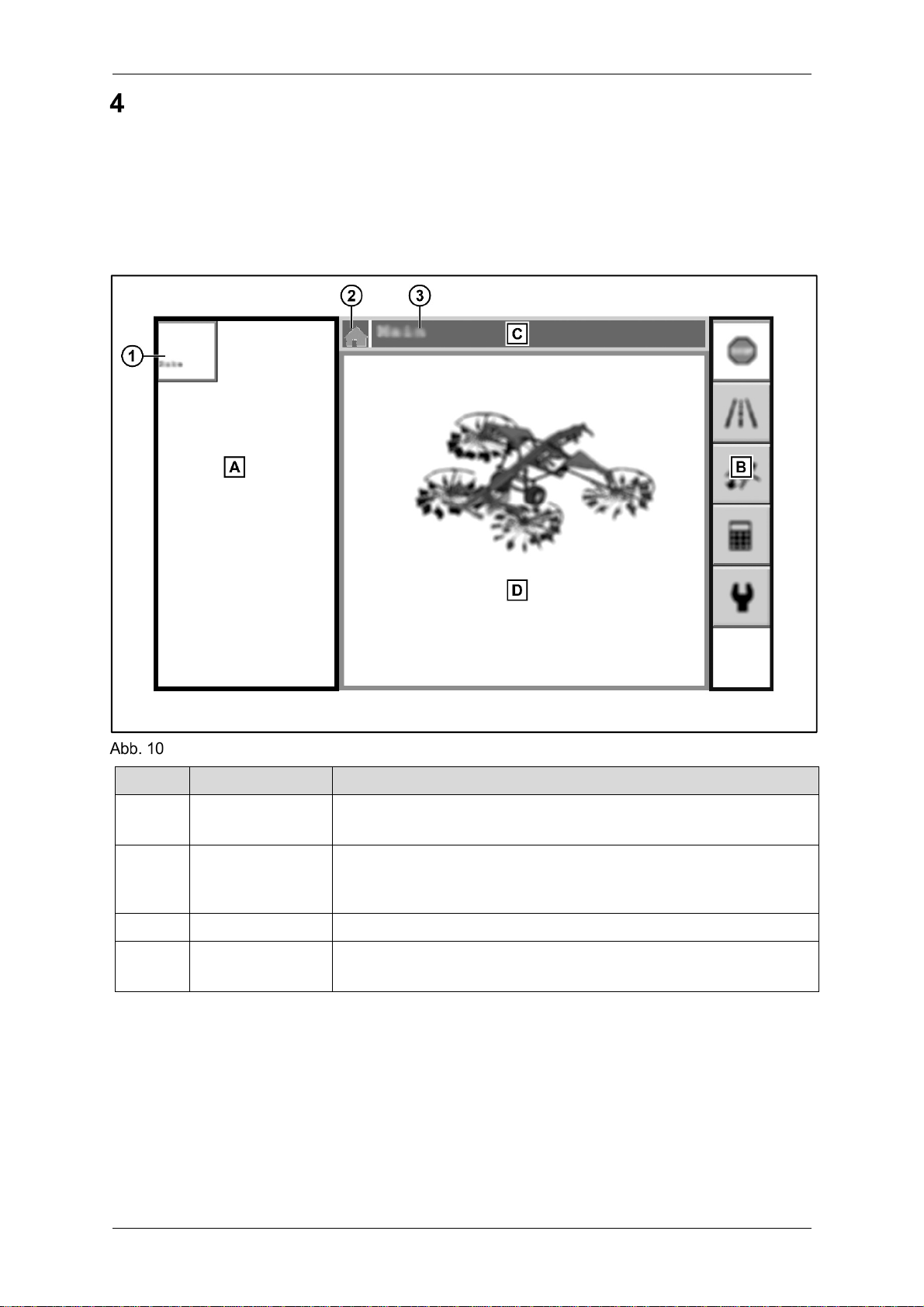
4.1 Display layout
A schematic diagram of the display is described below. The display on the actual ISOBUS
terminal may differ from the diagram.
Four sections are shown on the display. The software for each ISOBUS component contains
one or more menus.
Schematic diagram
Section Designation Description
A Component menu - All ISOBUS components are displayed
- There is a button for every ISOBUS component (1)
B Button panel - Displays buttons for selecting different menus or implementing
actions
- The buttons displayed depend on the menu
C Header - Shows the symbol for (2) and tile of (3) the current menu
D Function section - Section for displays, images and specific settings
- Contents depend on which menu is open

ISOBUS control system
FORMER 12545 PRO 17
4.2 General buttons
There are three buttons with general functions.
Button Function
Stop - The action being implemented is interrupted and the "Man-
ual Operation" menu opens
Back - Goes back to the previous menu
- Stops an action being implemented
Next - Changes the buttons that are visible in the panel
- Only available when there are more buttons in the menu
than can be displayed at one time

ISOBUS control system
18 FORMER 12545 PRO
4.3 Menus
4.3.1 Menu structure
The software has various menus for operating the machine. Every menu has a specific icon
and a unique title in the header.
Transport
Main menu Lifting/Lowering Working Setup
On-Board Computer Manual Operation
User Setup Headland Position
Calibrations
Diagnostics
Factory Settings
Menu structure
4.3.2 "Main menu"
The "Main menu" is displayed when the software is started. The model of the machine, the
manufacturer's logo and a version number are displayed in the functions section.
Button Function
Transport - The "Transport" menu opens.
Lifting/Lowering - The "Lifting/Lowering" menu opens
- Hidden when the machine is in the transport position
Table of contents
Other FENDT Farm Equipment manuals


