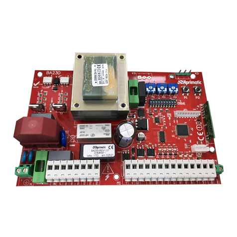
Aprimatic SC 24 Operation instructions

LBT0499 – DS41627-001 – FW 1.01 2020
SCOPO DEL MANUALE
Questo manuale è stato redatto dal costruttore ed è parte integrante del prodotto.
In esso sono contenute tutte le informazioni necessarie per:
• la corretta sensibilizzazione degli installatori alle problematiche della sicurezza;
• la corretta installazione del dispositivo;
• la conoscenza approfondita del suo funzionamento e dei suoi limiti;
• il corretto uso in condizioni di sicurezza;
La costante osservanza delle indicazioni fornite in questo manuale, garantisce la sicurezza dell’uomo, l’economia
di esercizio e una più lunga durata di funzionamento del prodotto.
Al fine di evitare manovre errate con il rischio di incidenti, è importante leggere attentamente questo manuale,
rispettando scrupolosamente le informazioni fornite.
Le istruzioni, i disegni, le fotografie e la documentazione contenuti nel presente manuale sono di proprietà
APRIMATIC S.p.a. e non possono essere riprodotti in alcun modo, né integralmente, né parzialmente.
Il logo “APRIMATIC” è un marchio registrato di APRIMATIC s.r.l..
PURPOSE OF THE MANUAL
This manual was drawn up by the manufacturer and is an integral part of the product.
It contains all the necessary information:
• to draw the attention of the installers to safety related problems
• to install the device properly
• to understand how it works and its limits
• to use the device under safe conditions
Strict observance of the instructions in this manual guarantees safe conditions as well as efficient operation and
a long life for the product.
To prevent operations that may result in accidents, read this manual and strictly obey the
instructions provided.
Instructions, drawings, photos and literature contained herein are the exclusive property of the
manufacturer and may not be reproduced by any means.
The “Aprimatic” logo is a trademark registered byAprimatic s.r.l..
BUT DU MANUEL
Ce manuel a été rédigé par le constructeur et fait partie intégrante du produit.
Il contient toutes les informations nécessaires pour :
sensibiliser les installateurs aux problèmes liés à la sécurité ;
installer le dispositif de manière correcte ;
connaître le fonctionnement et les limites du dispositif ;
utiliser correctement le dispositif dans des conditions de sécurité optimales ;
Le respect des indications fournies dans ce manuel garantit la sécurité personnelle, une économie de fonctionnement
et une longue durée de vie du produit.
Afi n d’éviter des opérations incorrectes et de ne pas risquer des accidents sérieux, lire attentivement ce manuel et
respecter scrupuleusement les informations fournies.
Les instructions, les dessins, les photos et la documentation contenus dans ce manuel sont la propriété d’APRIMATIC
S.p.A. et ne peuvent être reproduits sous aucune forme, ni intégralement, ni partiellement.
Le logo « Aprimatic » est une marque déposée par Aprimatic s.r.l..
ZWECK DES HANDBUCHS
Dieses Handbuch wurde vom Hersteller verfasst und ist ein ergänzender Bestandteil des Produkts.
Es enthält alle nötigen Informationen für:
• die Sensibilisierung der Monteure für Fragen der Sicherheit;
• die vorschriftsm ßige Installation der Vorrichtung;
• die umfassende Kenntnis ihrer Funktionsweise und ihrer Grenzen;
• die vorschriftsmäßige und sichere Benutzung.
Die Beachtung der in diesem Handbuch enthaltenenAnweisungen gewährleistet die Sicherheit der Personen, den
wirtschaftlichen Betrieb und eine lange Lebensdauer des Produkts.
Zur Vermeidung von Fehlbedienung und somit Unfallgefahr dieses Handbuch aufmerksam durchlesen und die
Anweisungen genau befolgen.
Die Anleitungen, Zeichnungen, Fotos und Dokumentationen in diesem Handbuch sind Eigentum vonAPRIMATIC
S.p.A. und dürfen in keiner Weise ganz oder teilweise reproduziert werden.
Das Logo „Aprimatic“ ist ein eingetragenes Warenzeichen derAprimatic s.r.l
.
OBJETO DEL MANUAL
Este manual ha sido redactado por el constructor y forma parte integrante del producto.
El mismo contiene todas las informaciones necesarias para:
• la correcta sensibilización de los instaladores hacia los problemas de la seguridad
• la correcta instalación del dispositivo
• el conocimiento en profundidad de su funcionamiento y de sus límites
• el correcto uso en condiciones de seguridad
La constante observación de las indicaciones suministradas en este manual, garantiza la seguridad del hombre,
la economía del ejercicio y una mayor duración de funcionamiento del producto.
Con el fi n de evitar maniobras equivocadas con riesgo de accidente, es importante leer atentamente este manual,
respetando escrupulosamente las informaciones suministradas.
Las instrucciones, los dibujos, las fotografías y la documentación que contiene este manual son propiedad de
APRIMATIC S.p.a. y no pueden ser reproducidas en ninguna manera, ni integral ni parcialmente.
El logotipo “Aprimatic” es una marca registrada de Aprimatic s.r.l..
SC 24
Apparecchiatura di controllo per automazione di cancelli scorrevoli a 24 V
Unit for the automatic control of sliding gates 24 V
Platine de commande pour l’automatisation de portails coulissants 24 V
Steuereinheit für Schiebetore 24 V
Equipo de control para la automatización de cancelas correderas 24 V
Istruzioni di installazione elettrica
Uso e Manutenzione
Electrical installation,
Use and Maintenance Instructions
Instructions d’installation éléctrique,
d'Utilisation et d’Entretien
Anleitung für die elektrische Installation,
Gebrauch und Wartung
Instrucciones para la instalación electrica,
el uso y el mantenimiento
ItalianoEnglishFrançaisEspañol Deutch

LBT0499 – DS41627-001 – FW 1.01 - 2020
REMESSA AL MANUALE ISTRUZIONI
Le presenti istruzioni riguardano esclusivamente l’installazione elettrica e l’utilizzo del sistema di controllo con
apparecchiatura SC24.
La predisposizione dei collegamenti elettrici di tutti i dispositivi del proprio sistema deve essere effettuata prima di iniziare
l’installazione dei componenti, attenendosi allo schema di “Predisposizione dell'impianto elettrico" fornito nel manuale
istruzioni dell'attuatore, alle avvertenze fornite in questo manuale e alle istruzioni allegate ai componenti installati.
Nel corso delle operazioni di assemblaggio e montaggio e collaudo dell’automatismo si possono verificare situazioni di
pericolo se non si osservano le avvertenze di sicurezza contenute nelle istruzioni. Prima di procedere leggere attentamente il
presente manuale istruzioni. Rendere disponibili le istruzioni presso l’impianto per ogni necessità di utilizzo e manutenzione.
Le istruzioni dei prodotti Aprimatic sono reperibili sul sito www.aprimatic.it
I dati riportati sono da ritenersi puramente indicativi. Il costruttore declina ogni responsabilità per le possibili inesattezze
contenute nel presente manuale derivanti da errori di stampa o di trascrizione.
L’azienda si riserva il diritto di apportare modifiche atte a migliorare il prodotto senza preavviso.
AVVERTENZE GENERALI E DI SICUREZZA
Leggere attentamente le istruzioni prima di iniziare l’installazione del prodotto.
I materiali dell’imballaggio (plastica, polistirolo, ecc.) non vanno dispersi nell’ambiente e non devono
essere lasciati alla portata dei bambini in quanto potenziali fonti di pericolo. La non corretta installazione dell’apparecchiatura
può provocare gravi pericoli, seguire attentamente tutte le istruzioni per l’installazione. Si raccomanda di lavorare nel pieno
rispetto delle norme di sicurezza; di operare in ambiente sufficientemente illuminato e idoneo per la salute; di indossare
indumenti di protezione a norma di legge (scarpe antinfortunistiche, occhiali di protezione, guanti ed elmetto) evitando di
indossare articoli di abbigliamento che possano impigliarsi. adottare misure di protezione adeguate al rischio di ferita dovuto a
schegge acuminate e ai possibili rischi di schiacciamento, urto e cesoiamento. Si raccomanda di osservare rigorosamente le
norme nazionali valide per la sicurezza nei cantieri. Delimitare il cantiere per impedire il transito a persone non autorizzate e
non lasciare incustodita la zona di lavoro. Installazione, collegamenti elettrici e regolazioni devono essere effettuati
nell’osservanza della buona tecnica e in ottemperanza alle norme vigenti nel paese di installazione. Il costruttore della
motorizzazione non è responsabile dell’inosservanza della buona tecnica nella costruzione della struttura da motorizzare, né
delle deformazioni che dovessero intervenire nell’utilizzo.
Un’errata installazione può essere fonte di pericolo. Eseguire gli interventi come specificato dal costruttore.
Prima di iniziare l’installazione, verificare l’integrità del prodotto e verificare che la struttura esistente abbia i necessari requisiti
di robustezza e stabilità e che risponda alle normative di settore vigenti. L’installazione, il collaudo e la messa in funzione della
chiusura pedonale, così come le verifiche periodiche e gli interventi di manutenzione, possono essere eseguiti soltanto da
tecnici specializzati e formati sul prodotto.
L’intero impianto deve essere realizzato da personale qualifi cato e in perfetta conformità con le norme vigenti nel Paese di
installazione (norme CEI 64 - 8 / EN 60335-1).
E’ necessario seguire un corso di specializzazione. A questo scopo gli installatori sono invitati a contattare il fornitore.
L’apparecchiatura SC24 è stata progettata per controllare il funzionamento di attuatori
elettromeccanici a 24V per l'automazione di cancelli scorrevoli.
È vietato utilizzare il prodotto per scopi diversi da quelli previsti o impropri. Si raccomanda di attenersi
altresì ai limiti di impiego indicati nel manuale di installazione dell'attuatore. È vietato manomettere o modificare il
prodotto. Il prodotto deve essere istallato solo con materiale APRIMATIC.
Aprimatic srl non assume responsabilità per il mancato rispetto di tali prescrizioni.
L’apparecchio può essere utilizzato da bambini di età non inferiore a 8 anni e da persone con ridotte
capacità fisiche, sensoriali o mentali, o prive di esperienza o della necessaria conoscenza, purché sotto
sorveglianza oppure dopo che le stesse abbiano ricevuto istruzioni relative all’uso sicuro dell’apparecchio e alla
comprensione dei pericoli ad esso inerenti.
I bambini devono essere sorvegliati affinchè non giochino con l’apparecchio, incluso il telecomando. La pulizia e la
manutenzione destinata ad essere effettuata dall’utilizzatore non deve essere effettuata da bambini senza
sorveglianza.
L’impianto di alimentazione elettrica deve essere eseguito da un elettricista esperto e abilitato secondo
i criteri nazionali, nel rispetto delle norme nazionali di sicurezza degli impianti.
Prima di collegare l’alimentazione elettrica accertarsi che i dati di targa siano rispondenti a quelli della rete di distribuzione
elettrica. Le misure di protezione sul primario vengono adottate in cantiere / in opera.
L'apparecchio deve essere assicurato ad un interruttore (anche magnetotermico se del caso) che assicuri la disconnessione
onnipolare della rete. Come interruttore generale della tensione di rete utilizzare un interruttore differenziale magnetotermico
di 6A a intervento 30mA, categoria III.
Prima di procedere a qualsiasi intervento di manutenzione, riparazione o sostituzione sia meccaniche che elettriche è
necessario interrompere l’alimentazione elettrica di rete.
Il collaudo e la messa in funzione dell’automazione non sono consentiti fino a quando non sia stato verificato che il cancello

LBT0499 – DS41627-001 – FW 1.01 2020
automatico scorrevole è conforme alla quale il cancello completo, montato e installato è assoggettato.
l’installatore deve verificare che il range di temperatura indicato in etichetta sia compatibile con il luogo di installazione.
L’installatore è tenuto a produrre e conservare il fascicolo tecnico del cancello automatico e deve ottemperare a tutti gli
adempimenti previsti. al termine del lavoro l’installatore deve verificare l’installazione e il corretto funzionamento
dell’automazione.
Deve eseguire l’analisi dei rischi e verificare che l’impianto non presenti punti di schiacciamento o cesoiamento. Se
necessario deve adottare adeguate misure correttive e applicare le segnalazioni previste dalle norme vigenti per individuare le
zone pericolose.
Ogni installazione deve riportare in modo visibile l’indicazione dei dati identificativi del sistema motorizzato.
L’installatore deve fornire tutte le informazioni relative al funzionamento automatico, manuale e di emergenza del cancello
motorizzato e consegnare le istruzioni d’uso all’utilizzatore dell’impianto. per eventuali riparazioni o sostituzioni dovranno
essere utilizzati esclusivamente ricambi originali.
Non si riconosce la garanzia in caso di utilizzo combinato con componenti di altra marca.
Il costruttore della motorizzazione declina ogni responsabilità qualora vengano installati componenti incompatibili ai fini della
sicurezza e del buon funzionamento. Impianto tipo
• L’intero impianto deve essere realizzato in perfetta conformità con le norme CEI 61 - 1 e CEI 64 – 8
• L’installatore deve verificare che il range di temperatura indicato in etichetta sia compatibile con il luogo di
installazione.
• Gli accessori indicati in figura non sono forniti con l’apparecchiatura.
• Utilizzare per gli allacciamenti cavo elettrico sezione 1,5 mm2 FROR CEI 20-22.
• Per il fissaggio del box plastico dell’apparechiatura utilizzare i fori prestampati nel box, fissare con tasselli adatti
al supporto che si è scelto e sigillare con silicone.
• Se si rendesse necessario inserire una guaina di protezione nel cavo di alimentazione dell’attuatore, eseguire
l’operazione prima .
di effettuare l’allacciamento del cavo stesso alle scatole di derivazione.
• Se il cavo di alimentazione dovesse essere danneggiato, esso deve essere sostituito dal servizio di assistenza
tecnica qualificato.

LBT0499 – DS41627-001 – FW 1.01 - 2020
Descrizione della centrale
La centrale di comando modello SC24 è adatta a comandare un attuatore per cancello a singola anta
scorrevole con potenza massima motore di 100W. L’assorbimento massimo del dispositivo è di 150W
a 230V 50Hz. L’impostazione dei parametri deve essere fatta dopo aver installato l’impianto completo.
TR1 – TR3 Trimmer regolazione
DSW1 Dip Switch impostazioni logiche - configurazione
P1 Pulsante apprendimento corse
P2 Pulsante apprendimento telecomandi
DL1 – DL9 LED segnalazione stato ingressi
DL10 LED bicolore rosso/verde/arancio di Test e Programmazione
DLR LED blu di presenza rete
F1 Fusibile di protezione accessori e logica F2A rapido
F2 Fusibile di protezione del secondario trasformatore e motore T8A
ritardato
M1 Morsettiera ingressi e uscite accessori
M2 Connettore/Morsettiera uscita motore e ingresso encoder
M5 Morsettiera finecorsa
FST1-FST2 Morsettiera alimentazione dal secondario trasformatore 22Vac
M4 Morsettiera antenna
CN1 Connettore encoder se presente
CN3 Connettore carica batterie (codice opzionale 41629/052 oppure
41629/051)
K3 Connettore ad innesto per ricevente
CN2 Connettore per scheda opzionale uscita telecomado (codice opzionale
MCH2 41626/050)
JF1 Connettore per dispositivo di aggiornamento
U2 Microcontrollore
RK1-RK2 Relè uscite motore

LBT0499 – DS41627-001 – FW 1.01 2020
MORSETTIERA M1
9 FL- Uscita lampeggiante -24Vcc 10W max
10
FL+ Uscita lampeggiante +24Vcc 10W max
11
+TST Uscita a positivo per test sicurezze (*)
12
+WL Positivo luce spia WL 24V cc 100mA max
13
COM Comune ingressi e luce spia WL (negativo)
14
SAF Ingresso (N.C.) sicurezze in apertura e chiusura (stop con breve
inversione)
15
PH2 Ingresso (N.C.) sicurezze in apertura e chiusura (stop
momentaneo)
16
PH1 Ingresso (N.C.) sicurezze in chiusura (riapertura)
17
STOP Pulsante (N.C.) arresto (stop)
18
SEQ Pulsante start (N.A.) apertura chiusura (sequenziale o start)
19
PED Pulsante (N.A.) apertura pedonale
20
OPEN Pulsante (N.A.) apertura (OPEN)
22
-AS Negativo alimentazione accessori 24V cc 500mA max
23
+AS Positivo alimentazione accessori 24V cc 500mA max
(*) : Per utilizzare il Test fotocellule è necessario collegare il positivo dei TX fotocellule al morsetto +TEST 11 di M1
MORSETTIERA/CONNETTORE M2
4 M1A Uscita motore 24V
5 M1B Uscita motore 24V
6 - ENC Negativo encoder
7 S.ENC Ingresso TTL segnale encoder
8 + ENC Positivo 5Vdc encoder
I contatti normalmente chiusi non utilizzati vanno ponticellati.
E’ PROIBITO COLLEGARE IL LAMPEGGIANTE O ALTRI ACCESSORI SU MORSETTI DIVERSI DA QUELLI PER I QUALI
SONO PREDISPOSTI.
Se uno o più ingressi NORMALMENTE APERTI (SEQ, PED, OPEN) è chiuso il LED DL10 lampeggia VERDE ad alta
frequenza.
Se uno o più ingressi NORMALMENTE CHIUSI (STOP, PH1, PH2, SAF) è aperto, il LED DL10 lampeggia ROSSO ad
alta frequenza.
Se sono attivi contemporaneamente ingressi di entrambe le tipologie il LED DL10 lampeggia ARANCIO ad alta frequenza
In questo caso NON E’ POSSIBILE eseguire la manovra di apprendimento corse.
Configurazioni del DIP SWITCH DSW1
Tramite i dip switch DSW1 è possibile configurare le seguenti funzioni della centrale facendo riferimento alla tabella di
seguito:
Dip
switch Funzione ON OFF
1 Chiusura automatica Abilitata Disabilitata
2 Logica di funzionamento Apre-Chiude Apre-Stop-Chiude-Apre
3 Funzione cortesia su fotocellula Abilitata Disabilitata
4 Condominiale Abilitata Disabilitata
5 Direzione apertura Destra Sinistra
6 Prelampeggio Abilitato Disabilitato
7 Tipo lampeggiante Fisso Intermittente
8 Input sicurezze sorvegliate Presenti Non presenti
9 Tipo ingresso SAF Resistivo 8K2 Digitale (N.C.)
10 Tipo encoder Riservato Onda 624
11 Funzionamento Low Power Abilitato Disabilitato
12 Richiusura automatica su arresto
sequenziale e pedonale Abilitato Disabilitato

LBT0499 – DS41627-001 – FW 1.01 - 2020
Descrizione delle funzioni del DIP SWITCH DSW1
1- Il dip 1 di chiusura automatica se abilitato permette di far richiudere automaticamente dopo il tempo di sosta (da
cancello aperto).
2- Il dip 2 modifica la sequenza di funzionamento degli ingressi SEQ (sequenziale) e PED (pedonale) anche da
telecomando.
3- Il dip 3 se abilitato permette la richiusura dopo 5 sec dal passaggio sulle fotocellule collegate all’ingresso PH1.
4- Il dip 4 è la funzione condominiale se abilitato fa si che il cancello in fase di apertura ignori eventuali comandi
provenienti dagli ingressi SEQUENZIALE, PEDONALE e in fase di pausa ricarichi il tempo di sosta.
5- Il dip 5 inverte la direzione di apertura del motore
6- Il dip 6 abilita la funzione di prelampeggio 3 secondi prima dell’inizio di ogni movimento.
7- Il dip 7 serve per configurare l’uscita del lampeggiante in caso vengano collegati lampeggianti autonomi (che
lampeggiano autonomamente) posizione ON, oppure lampeggianti che necessitano di un’uscita già condizionata
posizione OFF.
8- Il dip 8 configura l’uscita +TEST. Se abilitato la funzione d’uscita è di test sicurezze (vedi esempio collegamento pag
14).
9- Il dip 9 configura nell’ingresso SAF il tipo costa, resistiva 8K2 oppure digitale N.C.
10- Il dip 10 seleziona il tipo di encoder montato nel motore (se presente).
11- Il dip 11 abilita il funzionamento low power spegnendo gli accessori in standby.
12- Il dip 12 se abilitato configura l’arresto gestito dal sequenziale e pedonale non più come stop ma fermata con tempo
di pausa e richiusura automatica.
Regolazioni dei Trimmer
Il trimmer TR1 DELAY regola il tempo di sosta (tempo nel quale il cancello resta fermo prima della chiusura automatica).
Il trimmer TR2 TORQUE regola la sensibilità all’ostacolo del motore.
Il trimmer TR3 SL regola la velocità in fase di rallentamento dei motore.
Apprendimento telecomandi
La centrale di comando SC24 è dotata di un decodificatore incorporato capace di memorizzare fino a 300 telecomandi di tipo
rolling code KeeLoq®.
Apprendimento del telecomando nella funzione SEQUENZIALE (SEQ o START)
Premere il pulsante P2 e tenerlo premuto fino a quando il led DL10 prg comincia a lampeggiare di colore arancio (prima
frequenza di lampeggio). Rilasciare il pulsante P2. Entro 10 secondi premere il tasto del telecomando da apprendere che si
desidera sia associato al comando di SEQUENZIALE (START). L'avvenuto apprendimento sarà segnalato dall’accensione
verde fissa del led DL10.
Ripetere l'operazione per ogni telecomando da apprendere.
Apprendimento del telecomando nella funzione PEDONALE (PED)
Premere il pulsante P2 e tenerlo premuto fino a quando il led DL10 prg comincia a lampeggiare di colore arancio; non
rilasciare il pulsante e attendere che il lampeggio diventi più veloce (seconda frequenza di lampeggio). Rilasciare il pulsante
P2.Entro 10 secondi premere il tasto del telecomando da apprendere che si desidera sia associato al comando PEDONALE.
L'avvenuto apprendimento sarà segnalato dall’accensione verde fissa del led DL10.
Ripetere l'operazione per ogni telecomando da apprendere.
Apprendimento del telecomando nella funzione USCITA AUX (SCHEDA MCH2)
Premere il pulsante P2 e tenerlo premuto fino a quando il led DL10 prg comincia a lampeggiare di colore arancio; non
rilasciare il pulsante e attendere che il lampeggio diventi più veloce (terza frequenza di lampeggio). Rilasciare il pulsante P2.
Entro 10 secondi premere il tasto del telecomando da apprendere che si desidera sia associato al comando della schedina
MCH2. L'avvenuto apprendimento sarà segnalato dall’accensione verde fissa del led DL10.
Ripetere l'operazione per ogni telecomando da apprendere.
Cancellazione di un singolo telecomando appreso
Premere il pulsante P2 e tenerlo premuto fino a quando il led DL10 comincia a lampeggiare di colore arancio non rilasciare il
pulsante e attendere che il lampeggio diventi più veloce fino alla quarta frequenza di lampeggio. Rilasciare il pulsante P2
Entro 10 secondi premere il tasto del telecomando da cancellare. L'avvenuta cancellazione sarà segnalato dall’accensione
verde fissa del led DL10.
Cancellazione di tutti i telecomandi appresi
Premere il pulsante P2 alimentando la centrale e attendere che il led DL10 finisca di lampeggiare con il colore rosso, dopo di
che rilasciare il pulsante.
Trimmer Funzione Range Funzioni speciali
TR1 - DELAY Tempo sosta Da 1 a 180 sec
TR2 – TORQ. Sensibilità ostacolo
TR3 - SL Velocità di rallentamento Da 1 a 60%

LBT0499 – DS41627-001 – FW 1.01 2020
Procedura apprendimento e cancellazione telecomandi
Cancellazione totale di tutti i telecomandi
Procedura manuale di messa a punto per posizionare il cancello
Per poter eseguire delle manovre di posizionamento del cancello prima di iniziare eventuali apprendimenti o verifiche dei
collegamenti è presente una funzione che permette di muovere in modalità uomo presente il motore con la velocità impostata
nel trimmer:
TR3 velocità rallentamento adottata nel movimento di chiusura.

LBT0499 – DS41627-001 – FW 1.01 - 2020
Per entrare in questa modalità premere contemporaneamente i due pulsanti P1 e P2, a questo punto il led DL10 si accenderà
fisso con il colore arancio segnalando la modalità di messa a punto uomo presente. Rilasciare i pulsanti. (vedi figura sopra).
Ora come si può vedere dalla figura qui sotto pulsante P1 comanda in modo ciclico il motore. Sarà sufficiente tenere premuto
per far muovere il motore e questo ad ogni nuova pressione invertirà il senso di marcia avendo così il controllo completo delle
due direzioni.
Il led DL10 indicherà a seconda del colore la direzione del motore in modo da verificare anche i collegamenti dei rispettivi
motori:
Rosso = direzione chiusura
Verde = direzione apertura
Procedura apprendimento della corsa
Per entrare in programmazione della corsa tenere premuto il pulsante P1 fino a che il led DL10 prg comincia a lampeggiare di
colore verde (prima frequenza di lampeggio). Rilasciare il pulsante P1, quindi seguire le fasi di programmazione riportate di
seguito. La programmazione termina quando il led DL10 si spegne.
Iniziare la procedura a cancello chiuso.
Nella procedura di apprendimento delle corse è possibile usare oltre al tasto P2 della centrale anche il pulsante
appreso come SEQ del telecomando oppure il tasto collegato all’ingresso SEQ
ATTENZIONE!
Se non si desidera usare i rallentamenti non eseguire le fasi indicate dall’asterisco, ogni volta che viene modificata la
velocità di rallentamento bisogna rifare l’apprendimento ottenendo così le variazioni desiderate.
LACENTRALE ORAESEGUIRA’IN MODO
AUTOMATICO UNAMANOVRACOMPLETA
PER APPRENDERE LE CORRENTI, AL
TERMINE DI QUESTA IL LED DL11
LAMPEGGERA’VELOCEMENTE E POI SI
SPEGNERA’INDICANDO LAFINE
DELL’APPR
ENDIMENTO.

LBT0499 – DS41627-001 – FW 1.01 2020
Schede e accessori opzionali
- SCHEDA CARICA BATTERIE (41629/052)
Questo accessorio opzionale permette di collegare le
batterie alla centrale controllando la loro carica ottimale e
aumentandone la loro durata.
Durante il funzionamento a batteria la durata di accensione del
lampeggiante si riduce e la luce spia cambia la segnalazione di stato non
chiuso da accesa a brevi accensioni.
- CAVO CARICA BATTERIE (41629/051)
Questo accessorio opzionale permette di collegare le batterie alla
centrale.
Durante il funzionamento a batteria la durata di accensione del lampeggiante si riduce e la luce spia cambia la segnalazione
di stato non chiuso da accesa a brevi accensioni
.
- SCHEDA USCITA AUSILIARIA (codice MCH2 41626/050)
Questa scheda opzionale permette di avere
un’uscita con contatto pulito in scambio, gestita
da telecomando. Inserirla con centrale spenta nel
connettore CN2, come mostrato nella figura qui
a fianco sulla sinistra.
Rispetta la funzione passo-passo non
temporizzata e non settabile.
Significato delle sigle
N.C. = contatto normalmente chiuso
N.A. = contatto normalmente aperto
Segnalazione di errore o anomalia
Le eventuali segnalazioni di errore o anomalia avvengono contemporanamente attraverso il led rosso DL10, l’uscita
luce spia e l’uscita lampeggiante:
- 3 lampeggi = apprendimento fallito
- 4 lampeggi = test sicurezze fallito
- 5 lampeggi = encoder o motore guasti

LBT0499 – DS41627-001 – FW 1.01 - 2020
Esempio di collegamento
Caratteristiche tecniche
Tensione alimentazione monofase
230Vca +6%-10%
Frequenza
50/60Hz
Cicli operativi per ora massimi
30
Alimentazione motore
24Vdc
Tensione per dispositivi esterni
(AS)
28Vdc +10%-8%
Corrente massima dispositivi
esterni
500mA su accessori (AS) + 500mA su lampeggiante
Consumo apparecchiatura (stand
by)
3W
Potenza massima motore
100W per 5 sec
Protezione primario
trasformatore
Fusibile ritardato da T1A (Fusibile nel morsetto A)
Protezione secondario
trasformatore
Fusibile ritardato da T8A (F2)
Protezione accessori e scheda
24Vdc
Fusibile rapido da F2A (F1)
Temperatura di funzionamento
-20/+55°C
Pressione sonora
LpA≤70 dB (A)
Grado di protezione
Dipendente dal contenitore
Dimensioni scheda (LxHxP)
120x120x40 mm
Versione Firmware
V2.xx
Capacità della ricevente integrata
300 codici (rolling code)
Frequenza del modulo radio 433,92 MHz OOK con ricevitore integrato
Telecomandi compatibili
Aprimatic Italiano e Spagnolo
Il prodotto è conforme alle seguenti direttive 2014/35/EU
–
2014/30/EU
–
2014/53/EU
Il costruttore si riserva di apportare modifiche al prodotto senza preavviso, quindi questo manuale potrebbe non corrispondere
esattamente alle specifiche del prodotto. Verificare sempre la versione firmware nel manuale e della scheda

LBT0499 – DS41627-001 – FW 1.01 2020
ABOUT THIS MANUAL
These instructions concern only the electrical installation and the use of the control system with the equipment SC24.
The presetting of the electrical connections of all devices of your system must be carried out before starting component installation,
following the “Electric system presetting” diagram provided in the actuator instruction manual, the warnings provided in this manual and
the instructions enclosed with the installed components.
During assembly, installation and test operations of the automatic device, hazardous situations might arise if the safety warnings contained
in the instructions are not followed. Carefully read this instruction manual before proceeding. Instructions must be available with the
system for any use or maintenance operation needed.
Instructions for Aprimatic products can be found at www.aprimatic.it
The data indicated are to be considered for indicative purposes only. The manufacturer is not to be held responsible for any inaccuracy
contained in this manual arising from printing or transcription mistakes.
The company reserves the right to make changes to improve the product without giving prior notice.
GENERAL SAFETY PRECAUTIONS
Carefully read the instructions before starting to install the product.
Packaging materials (plastic, polystyrene, etc.) must not be dispersed in the environment and must not be left
where children can reach them as they are a potential source of danger. Wrong installation of the equipment can cause serious danger.
Please, follow all installation instructions carefully. We recommend operating in a well-lit and healthy environment, in compliance with the
safety regulations in force. We recommend the use of approved protective clothing (safety shoes, protective goggles, gloves and helmet).
Do not wear articles of clothing that could get caught. Take adequate safety measures to prevent the risk of injury caused by sharp splinters
and the possible risks of crushing, knocks and cuts and amputation collision and shearing danger. We recommend strict observation of the
national regulations for safety in work sites. Delimit the yard to prevent any unauthorised persons from transiting in the working area. Do
not leave the working area unattended. Installation, electrical connections and adjustments must be carried out in a professional manner in
compliance with the good manufacturing and workmanship regulations in force in the country where the automation is installed. The
manufacturer of the device is not responsible for the non-observance of professional standards of work in the construction of the power-
driven structure, nor for any damage which may be caused by the use of the drive.
Incorrect installation may be dangerous. Follow the manufacturer's instructions.
Before starting installation, check that the product is intact and that the existing structure is suitably strong and stable and that it is
complying with the sector current regulations. Only suitably skilled technicians trained on the product are authorised to connect up, test
and put into service this product.
The whole system must be built by qualified personnel and in full compliance with the regulations in force in the country of installation
(standards CEI 64 - 8 / EN 60335-1).
We strongly recommend attending a specialised training course. Installers should contact the supplier for information on courses.
The equipment SC24 is designed to control functioning of 24-volt electromechanical actuators used to
automate sliding gates.
Do not use the product improperly or for purposes other than those specified. You should note the operating restrictions specified
in the installation manual supplied with the actuator. Do NOT tamper with or modify the product in any way. The product must
only be installed using APRIMATIC material.
Aprimatic srl declines all liability for damages caused by failure to follow these instructions.
The equipment can be used by children who are over 8 years of age and by persons with limited physical, sensory or mental
capacities, or inexperienced or unskilled persons, provided that they are under supervision or that they have been instructed about
the safe use of the equipment and inherent hazards.
Children must be supervised so that they do not play both with the equipment and the remote control. Cleaning and maintenance
operations intended to be carried out by the user must not be performed by unsupervised children.
The power supply system must be built by a qualified and expert electrician according to the local
requirements, in compliance with local system safety regulations.
Before connecting the power supply make sure that the plate data correspond to those of the electric power distribution grid. The
protection measures on the primary are used on site / in operation.
The equipment must be secured to a switch (including a thermal-magnetic circuit breaker if necessary) that ensures the omnipolar
disconnection of the mains. As main switch of the mains power, use a 6A magneto-thermal differential switch tripping at 30mA, category
III.
Disconnect the power supply before carrying out any other maintenance operation, repair or replacement, both mechanical and electrical.
Test and commissioning of the automatic device are not allowed until the sliding automatic gate has not been verified as complying with
the requirements that the finished, assembled and installed gate is subject to.
The installer must check that the temperature range indicated on the label is compatible with the place of installation.
The installer must keep and store the technical documentation of the automatic gate and must fulfil all obligations required. At the end of
the job the installer must check the installation and the correct operation of the automatic device.
Caution
Warning
Warning
Information

LBT0499 – DS41627-001 – FW 1.01 - 2020
The installer must carry out a risk analysis and check that the system does not feature crushing or shearing points. If necessary, corrective
measures must be implemented and signals required by current regulations must be applied in order to make the dangerous areas visible.
The identification data of the motorised system must be clearly visible on each installation.
The installer must provide full information about the automatic, manual and emergency functioning of the equipment and deliver the
operating instructions to the system user. Only use original spare parts for any repairs or for replacing parts.
The guarantee is void if this product is used in combination with others of other brands.
The manufacturer of the drive declines any responsibility if components incompatible with safety and correct operation are installed.
System type
• The whole system must be built in full compliance with standards CEI 61 - 1 and CEI 64 - 8
• The installer must check that the temperature range indicated on the label is compatible with the place of installation.
• The accessories shown in the figure are not supplied with the equipment.
• For connections use an electrical cable with a cross-section of 1.5 sq.mm FROR CEI 20-22.
• To fix the plastic box of the equipment use the pre-cut holes in the box, fix with plugs suitable for the support you have chosen
and seal with silicone.
• If a protection sheath is required on the actuator power cable, carry out this operation before
connecting the cable to the junction boxes.
• If the power cable is damaged, it must be replaced by qualified service personnel.
Control equipment...................................................
Actuator...................................................................
Antenna 433.92 MHz...............................................
Flashing light...........................................................
Pair of photocells.....................................................
Key-operated switch................................................
OPTIONAL control devices.....................................
Proximity reader*, Card reader*..............................
remote control
2 x 1.5 sq.mm + ground
3 x 1.5 sq.mm + ground
Supplied cable
2 x 1 sq.mm
Emitter 2 x 0.75 sq.mm: receiver 4 x 0.75 sq.mm
3 x 0.75 sq.mm
3 x 0.75 sq.mm
Gate keypad*
*optional accessory (refer to the sale catalogue)
Warning
Fig.7

LBT0499 – DS41627-001 – FW 1.01 2020
Description of the control unit
The control unit model SC24 is suitable to control one actuator for single-leaf sliding gate with a maximum
motor power of 100W. The maximum absorption of the device is 150W at 230V 50Hz. The parameters must be
set after the complete system has been installed.
TR1 – TR3 Adjustment trimmer
DSW1 Logic setting - configuration dip switch
P1 Stroke saving button
P2 Remote control saving button
DL1 – DL9 Input status signalling LED
DL10 Red/green/orange two-tone Test and Programming LED
DLR Blue voltage presence LED
F1 Quick F2A fuse for protection of accessories and logic
F2 Delayed T8A motor and transformer secondary protection fuse
M1 Accessory input and output terminal board
M2 Encoder input and motor output Terminal board/Connector
M5 Limit switch terminal board
FST1-FST2 22Vac transformer secondary power supply terminal board
M4 Antenna terminal board
CN1 Encoder connector, if present
CN3 Battery charger connector (optional code 41629/052 or 41629/051)
K3 Receiver plug-in connector
CN2 Connector for optional remote control output card (optional code MCH2
41626/050)
JF1 Connector for update device
U2 Microcontroller
RK1-RK2 Motor output relays
DELAY TORQ.

LBT0499 – DS41627-001 – FW 1.01 - 2020
M1 TERMINAL BOARD
9 FL- Beacon output -24Vdc 10W max
10
FL+ Beacon output +24Vdc 10W max
11
+TST Positive output for safety device testing (*)
12
+WL Positive terminal of warning light WL 24V dc 100mA max
13
COM Common terminal of inputs and warning light WL (negative)
14
SAF Input (N.C.) of opening and closing safety devices (stop with short
inversion)
15
PH2 Input (N.C.) of opening and closing safety devices (temporary
stop)
16
PH1 Input (N.C.) of closing safety devices (reopening)
17
STOP Stop button (N.C.)
18
SEQ Opening/closing (sequential or start) start button (N.O.)
19
PED Pedestrian gate opening button (N.O.)
20
OPEN Opening (OPEN) button (N.O.)
22
-AS Negative terminal of accessory power supply 24V dc 500mA max
23
+AS Positive terminal of accessory power supply 24V dc 500mA max
(*) : To use the Photocell Test it is necessary to connect the positive terminal of the photocell TX to the terminal +TEST 11 of
M1 M2 CONNECTOR/TERMINAL BOARD
4 M1A Motor 24V output
5 M1B Motor 24V output
6 - ENC Encoder negative terminal
7 S.ENC Encoder signal TTL input
8 + ENC 5Vcc encoder positive terminal
Normally closed contacts that are not used must be jumpered.
IT IS FORBIDDEN TO CONNECT THE BEACON OR OTHER ACCESSORIES TO TERMINALS OTHER THAN THOSE
FOR WHICH THEY ARE DESIGNED.
If one or more NORMALLY OPEN inputs (SEQ, PED, OPEN) is closed the DL10 LED flashes in GREEN at high
frequency.
If one or more NORMALLY CLOSED inputs (STOP, PH1, PH2, SAF) is open, the DL10 LED flashes in RED at high
frequency.
If both types of inputs are active at the same time, the DL10 LED flashes in ORANGE at high frequency
In this case, it is NOT POSSIBLE to perform the stroke saving manoeuvre.
DIP SWITCH DSW1 configuration
Through the dip switches DSW1 it is possible to configure the following functions of the central unit by referring to the table
below:
Dip
switch Function ON OFF
1 Automatic closing Enabled Disabled
2 Operating logic Open-Close Open-Stop-Close-Open
3 Courtesy light function on photocell Enabled Disabled
4 Condominium Enabled Disabled
5 Opening direction Right Left
6 Pre-flashing Enabled Disabled
7 Beacon type Fixed Intermittent
8 Supervised safety device input Present Not present
9 SAF input type 8K2 Resistive Digital (N.C.)
10 Encoder type Reserved Wave 624
11 Low Power Operation Enabled Disabled
12 Automatic re-closing on sequential
and pedestrian stop Enabled Disabled

LBT0499 – DS41627-001 – FW 1.01 2020
Description of DIP SWITCH DSW1 functions
13- The automatic closing dip switch 1, if enabled, allows the gate to close again automatically after the pause time (from
open gate).
14- Dip switch 2 changes the operating sequence of the SEQ (sequential) and PED (pedestrian) inputs also from remote
control.
15- Dip switch 3, if enabled, allows the gate to close again after 5 seconds from the passage on the photocells connected
to the PH1 input.
16- Dip switch 4 is the condominium function and, if enabled, it makes the gate ignore any commands coming from
SEQUENTIAL, PEDESTRIAN inputs during the opening phase and reload the pause time during the pause phase.
17- Dip switch 5 reverses the opening direction of the motor.
18- Dip switch 6 enables the pre-flashing function 3 seconds before the start of each movement.
19- Dip switch 7 is used to configure the beacon output to the ON position when autonomous beacons (that flash
independently) are connected, or to the OFF position in case of beacons that need an output already conditioned.
20- Dip switch 8 configures +TEST output. If enabled, the output function is for safety device testing (see connection
example on page 14).
21- Dip switch 9 configures the edge, 8K2 resistive or digital N.C. type in the SAF input.
22- Dip switch 10 selects the type of encoder fitted in the motor (if present).
23- Dip switch 11 enables low power operation turning off the accessories in standby.
24- If enabled, dip switch 12 configures the stop controlled by the sequential and pedestrian inputs no longer as a stop but
as a stop with pause time and automatic re-closing.
Trimmer Settings
The TR1 DELAY trimmer adjusts the pause time (time during which the gate remains stationary before automatic closing).
The TR2 TORQUE trimmer adjusts the obstacle detection sensitivity of motor.
The TR3 SL trimmer adjusts the speed during motor slowdown.
Saving the remote controls
The control unit SC24 is provided with an integrated decoder able to store up to 300 remote controls of rolling code KeeLoq®
type.
Saving remote control in SEQUENTIAL function (SEQ or START)
Press P2 button and keep it pressed until LED DL10 prg starts flashing in orange (first flashing frequency). Release P2
button. Within 10 seconds press the key of the remote control to be saved that you want to assign to the SEQUENTIAL
(START) control. Saving is completed when the LED DL10 is ON with a steady green light.
Repeat the operation for each remote control to save.
Saving remote control in PEDESTRIAN function (PED)
Press P2 button and keep it pressed until LED DL10 prg starts flashing in orange; do not release the button and wait for the
flashing to become faster (second flashing frequency). Release P2 button. Within 10 seconds press the key of the remote
control to be saved that you want to assign to the PEDESTRIAN control. Saving is completed when the LED DL10 is ON with
a steady green light.
Repeat the operation for each remote control to save.
Saving remote control in AUX OUTPUT function (MCH2 CARD)
Press P2 button and keep it pressed until LED DL10 prg starts flashing in orange; do not release the button and wait for the
flashing to become faster (third flashing frequency). Release P2 button.
Within 10 seconds press the key of the remote control to be saved that you want to assign to the MCH2 card control. Saving
is completed when the LED DL10 is ON with a steady green light.
Repeat the operation for each remote control to save.
Deleting a single saved remote control
Press P2 button and keep it pressed until LED DL10 starts flashing in orange do not release the button and wait for the
flashing to become faster (fourth flashing frequency). Release P2 button
Press the key of the remote control that you want to delete within 10 seconds. Deletion is completed when the LED DL10 is
ON with a steady green light.
Deleting all remote controls
Press P2 button, powering the control unit, and wait until the red LED DL10 stops flashing, then release the button.
Trimmer Function Range Special functions
TR1 - DELAY Pause time From 1 to 180 sec
TR2 – TORQ. Obstacle sensitivity
TR3 - SL Slowdown speed From 1 to 60%

LBT0499 – DS41627-001 – FW 1.01 - 2020
Remote control saving and deleting procedure
Total deletion of all remote controls
Manual setup procedure to position the gate
In order to be able to carry out some manoeuvres for positioning the gate before starting any saving or connection checking
operation, there is a function that allows moving the motor in deadman mode with the speed set in the trimmer
:
TR3 slowdown speed adopted in the closing movement.
PRESS FOR 3 SEC DL 10 FLASHING IN
ORANGE, 1ST
PRESS FOR 6 SEC
RELEASE P2
STORE THE REMOTE CONTROL
BUTTON ON SEQUENTIAL FUNCTION
DL 10 FLASHING IN
ORANGE, 2ND
RELEASE P2
RELEASE P2
STORE THE REMOTE CONTROL
BUTTON ON PEDESTRIAN FUNCTION
RELEASE P2
PRESS FOR 9 SEC DL 10 FLASHING IN
ORANGE, 3RD
STORE THE REMOTE CONTROL
BUTTON ON OPTIONALAUXILIARY
CARD OUTPUT
DL 10 FLASHING IN ORANGE, 4TH
FREQUENCY
PRESS FOR 12 SEC
DELETE SINGLE REMOTE
CONTROL
ACTION PERFORMED
DL 10 OFF
DL 10 STEADY ON
GREEN FOR 1 SEC
PRESS AND HOLD
POWER THE CONTROL UNIT
KEEP PRESSED DL 10 FAST FLASHING IN
RED FOR 10 SEC
DELETE ALL REMOTE CONTROLS
DL 10 STEADY ON GREEN FOR 3
SEC
DL 10 OFF
RELEASE P2
EXIT

LBT0499 – DS41627-001 – FW 1.01 2020
To enter this mode press the two buttons P1 and P2 at the same time, at this point LED DL10 will turn on with a steady
orange light indicating the deadman setup mode. Release buttons. (see figure above).
Now, as you can see in the figure below, the button P1 controls the motor in cyclic mode. Simply hold down the button to
make the motor move and this will reverse the direction with each new pressure, thus having complete control of the two
directions.
The LED DL10 colour will indicate the direction of the motor in order to check also the connections of the respective motors:
Red = closing direction
Green = opening direction
Stroke saving procedure
To enter the programming of the stroke, keep the button P1 pressed until the LED DL10 prg starts flashing in green (first
flashing frequency). Release button P1, then follow the programming steps below. Programming ends when LED DL10 turns
off.
Start the procedure with closed gate.
Besides the P2 button of the control unit, in the stroke saving procedure, you can use also the button saved as SEQ
on the remote control or the button connected to the SEQ input.
WARNING!
If you do not wish to use the slowdown settings, do not perform the steps indicated by the asterisk. Each time the
slowdown speed is changed, you have to repeat the saving to obtain the desired variations.
MOTOR CLOSING AT SLOWDOWN
SPEED SET IN TRIMMER TR3
RED
GREE
N
MOTOR OPENING AT MAXIMUM
SPEED
RELEASE BUTTON P1 AS SOON AS LED DL10 STARTS FLASHING GREEN
SLOW FLASHING OF LED
DL10
INDICATES
THE WAITING FOR A PULSE
1ST PULSE 2ND PULSE 3RD PULSE
PRESS P2 TO SET THE STARTING
POINT FOR CLOSING SLOWDOWN
PRESS P2 TO SET THE STARTING
POINT FOR OPENING SLOWDOWN
PRESS P2 TO START THE SAVING
OPERATION, IF THE GATE IS NOT AT THE
CLOSING LIMIT SWITCH THE FIRST
MANOEUVRE TO CARRYOUT WOULD BE TO
SLOWLY CLOSE THE GATE TO POSITION IT
PRESS P2 TO SET THE PARTIAL
OPENING POINT.
THE CONTROL UNIT WILL NOW
AUTOMATICALLY PERFORM A COMPLETE
MANOEUVRE TO SAVE THE CURRENTS, AFTER
WHICH LED DL11 WILL FLASH QUICKLY AND
THEN TURN OFF INDICATING THE END OF
THE SAVING OPERATION.

LBT0499 – DS41627-001 – FW 1.01 - 2020
Optional cards and accessories
- BATTERY CHARGER CARD (41629/052)
This optional accessory allows connecting the
batteries to the control unit controlling their optimal charge and
increasing their duration.
During battery operation the beacon ON time is reduced and the warning
light signalling the unclosed status changes from ON to shortly ON.
- BATTERY CHARGER CABLE (41629/051)
This optional accessory allows connecting the batteries to the control unit.
During battery operation the beacon ON time is reduced and the warning
light signalling the unclosed status changes from ON to shortly ON.
- AUXILIARY OUTPUT CARD (code MCH2 41626/050)
This optional card allows having
an output with dry changeover contact, controlled
via remote control. Insert it with control unit off in the
CN2 connector, as shown in the figure
on the left side.
It complies with the
not timed and non-settable stepper function.
Meaning of acronyms
N.C. = normally closed contact
N.O. = normally open contact
Error or fault signal
Any error or fault signals are issued simultaneously through the red LED DL10, the warning light output and the
beacon output:
- 3 flashes = saving failed
- 4 flashes = safety device test failed
- 5 flashes = faulty motor or encoder
BATTERY CHARGER

LBT0499 – DS41627-001 – FW 1.01 2020
Example of connection
Technical features
Single
-
phase power supply voltage
230Vca +6%-10%
Frequency
50/60Hz
Maximum operating cycles per
hour
30
Motor power supply
24Vdc
Voltage for external devices (AS)
28Vdc +10%-8%
Maximum external device current
500mA on accessories (AS) + 500mA on beacon
Equipment consumption (stand by)
3W
Maximum motor power
100W for 5 sec
Transformer primary protection
T1A delayed fuse (Fuse in terminal A)
Transformer secondary protect
ion
T8A delayed fuse (F2)
Accessories and 24Vdc card
protection
F2A quick fuse (F1)
Operating temperature
-20/+55°C
Sound pressure
LpA≤70 dB (A)
Protection class
According to container
Board size (LxHxW)
120x120x40 mm
Firmware version
V2.xx
Integr
ated receiver
capacity
300 codes (rolling code)
Radio module frequency 433.92 MHz OOK with integrated receiver
Compatible remote controls
Aprimatic Italian and Spanish
The product complies with the following Directives
2014/35/EU
-
2014/30/EU
-
2014/5
3/EU
The manufacturer reserves the right to make changes to the product without notice, so this manual may not exactly match the
specifications of the product. Always check the firmware version in the manual and on the board
ANTENNA
CLOSING LIMIT SWITCH
COMMON
OPENING LIMIT SWITCH
+24V ACCESSORIES
-24V ACCESSORIES
OPEN N.O.
PEDESTRIAN N.O.
SEQUENTIAL N.O.
STOP N.C.
PHOTOCELL 1 N.C.
PHOTOCELL 2 N.C.
SAFETY DEVICE N.C.
COMMON
+ WARNING LIGHT
+SAFETY DEVICE TEST
BROWN
GREEN
WHITE
BLUE
RED
* 24 VDC MAX 100W
OPTIONAL
BATTERY CHARGER
CARD
12 V (2-7Ah X2) LEAD BATTERIES
SECONDARY 22VAC
TRANSFORMER (230VAC
100VA)
PRIMARY 230VAC
NETWOR
K
230 VAC
50Hz
ENCODER
OPEN
STOP
STOP
OPEN

LBT0499 – DS41627-001 – FW 1.01 - 2020
INTRODUCTION AU MANUEL D’INSTRUCTIONS
Les présentes instructions concernent exclusivement l'installation électrique et l'utilisation du système de contrôle avec l'appareil SC24.
La prédisposition des branchements électriques de tous les dispositifs du système doit être effectuée avant de commencer l’installation des
composants, en respectant le schéma « prédisposition de l’installation électrique » fourni dans le manuel d’instructions de l'actionneur, les
avertissements fournis dans ce manuel et les instructions qui accompagnent les composants installés.
Lors de l’assemblage, du montage et de l’essai de l’automatisme, des situations dangereuses peuvent se produire, si les avertissements de
sécurité fournis dans le manuel d’instructions ne sont pas suivis. Avant de procéder, lire attentivement ce manuel d’instructions. Laisser le
manuel d’instructions à côté de l’installation afin qu’il soit disponible en cas de besoin d’utilisation ou d’entretien.
Vous trouverez les instructions pour les produits Aprimatic sur le site www.aprimatic.it
Les données du manuel ne sont fournies qu’à titre indicatif. Le constructeur décline toute responsabilité en ce qui concerne les possibles
inexactitudes contenues dans le présent manuel issues d'erreurs d'impression ou de transcription.
La société se réserve le droit d'apporter des modifications visant à améliorer le produit sans préavis.
AVERTISSEMENTS GÉNÉRAUX ET DE SÉCURITÉ
Lire attentivement les instructions avant de commencer l'installation du produit.
Les matériaux de l'emballage (plastique, polystyrène, etc.) ne doivent pas être dispersés dans l'environnement
et ne doivent pas être laissés à la portée des enfants car ce sont de potentielles sources de danger. L'installation incorrecte de l'appareil peut
comporter de graves dangers, suivre attentivement toutes les instructions d'installation. Il est recommandé de travailler dans le plein
respect des normes de sécurité, d'opérer dans un environnement suffisamment éclairé et idoine pour la santé, de porter des vêtements de
protection aux termes de la loi (chaussures de sécurité, lunettes de protection, gants et casque) en évitant de porter des pièces d'habillement
qui peuvent s'accrocher. Adopter des mesures de protection adéquates au risque de blessure dû aux éclats pointus et aux possibles risques
d'écrasement, choc et cisaillement. Il est recommandé d'observer rigoureusement les normes nationales valides pour la sécurité sur les
chantiers. Délimiter le chantier pour interdire le transit des personnes non autorisées et ne pas laisser la zone de travail sans surveillance.
L’installation, les branchements électriques et les réglages doivent être effectués dans le respect des règles de l’art et des règles en vigueur
dans le pays d’installation. Le fabricant de la motorisation n’est pas responsable du non-respect des règles de l’art dans la construction de
la structure à motoriser, ni des déformations dérivées de son utilisation.
Une mauvaise installation peut être une source de danger. Réaliser les interventions comme spécifié par le fabricant.
Avant de commencer l’installation, vérifier l’intégrité du produit et contrôler si la structure existante a les conditions nécessaires de solidité
et de stabilité et si elle respecte les réglementations industrielles en vigueur. L'installation, le test et la mise en fonction de la fermeture
piétonnière, ainsi que les vérifications périodiques et les interventions de maintenance, peuvent être réalisés seulement par des techniciens
spécialisés et formés sur le produit.
L’installation dans son ensemble doit être réalisée par un personnel qualifié et en parfaite conformité avec les règles en vigueur dans le
pays d’installation (normes CEI 64 - 8 / EN 60335-1).
Il est nécessaire de suivre un cours de spécialisation. À cette fin, les installateurs sont invités à contacter le fournisseur.
L'appareil SC24 a été conçu pour contrôler le fonctionnement des actionneurs électromécaniques en 24V
pour l'automation des portails coulissants.
Il est interdit d'utiliser le produit à des fins différentes de celles prévues ou impropres. Il est également recommandé de respecter
les limites d’utilisation indiquées dans le manuel d’installation de l’actionneur. Il est interdit d’altérer ou modifier le produit. Le
produit doit être installé seulement avec du matériel APRIMATIC.
Aprimatic s.r.l. n’assume aucune responsabilité quant au non-respect de ces prescriptions.
Cet appareil n’est pas destiné à être utilisé par des enfants âgés de moins de 8 ans ou par des personnes qui manquent d’expérience
et/ou de connaissance ou dont les capacités physiques, sensorielles ou mentales sont réduites, sauf si celles-ci sont sous la
surveillance ou ont reçu les instructions d’utilisation appropriées de la personne responsable de leur sécurité concernant
l’utilisation en toute sécurité de l’appareil et les risques associés.
Les enfants doivent être surveillés afin d’éviter qu’ils puissent jouer avec l’appareil, y compris la télécommande. Le nettoyage et
l’entretien destinés à être effectués par l’utilisateur ne doivent pas être effectués par des enfants sans supervision.
L'installation d'alimentation électrique doit être réalisée par un électricien expert et habilité selon les critères
nationaux, dans le respect des normes nationales de sécurité des installations.
Avant de brancher l'alimentation électrique, s'assurer que les données de la plaque signalétique correspondent à celles du réseau de
distribution électrique. Les mesures de protection sur le primaire sont adoptées sur le chantier/au travail.
L'appareil doit être associé à un interrupteur (même magnétothermique, le cas échéant) pouvant assurer la déconnexion de tous les pôles du
réseau. En guise d'interrupteur général de la tension du réseau, utiliser un interrupteur différentiel magnétothermique de 6A déclenchement
30mA, catégorie III.
Avant toute opération d’entretien, de réparation ou de remplacement, que ce soit mécanique ou électrique, il faut couper l’alimentation
électrique.
Le test et la mise en fonction de l'automatisme ne sont pas autorisés tant qu'il n'a pas été vérifié que le portail automatique coulissant est
conforme aux exigences auxquelles le portail complet, monté et installé est soumis.
L’installateur doit vérifier que la plage de température indiquée sur l’étiquette est compatible avec le lieu d’installation.
Prudence
Attention
Attention
Informations
Table of contents
Languages:
Other Aprimatic Door Opening System manuals