Michel's EZ-Lift User manual
Mul Mount Trailer Instrucons
0017-000001 - Michel's EZ-Li Kit for Flat Deck, Van, Cale Liner, and Small Trailers
Descripon:
The Michel’s EZ-Lift is a patent pending, torque amplifying gear box designed to raise and lower the Landing Gear on a
trailer. The Michel’s EZ-Lift has two reduction ratios, one for lighter loads to get the job done faster, and one for heavy
loads to effortlessly raise or lower your loaded trailer. This kit allows for a wide array of mounting options and is
designed to work with Flat Deck, Van, Cattle Liner, and Small Trailers.
The Michel’s EZ-Lift may be left on one trailer if desired and not removed between uses. Please Note that on some
trailers the EZ-Lift can put the trailer over Legal width and MUST be removed after use.
What is included:
1-Michel’s EZ-Lift
1-Mounting Bracket
1-Socket Adapter
1-STOP Decal
1-Mounting Bolt
1-Quick Pin
1-Quick Pin with chain
1-Lag screw
1-Instruction
1-Nut Key
*Warning the use of Hammer Drill or Impact will void the Warranty*

December 2023
Step 1:
Determine where and how the EZ-
Lift will be mounted onto the
landing gear.
Note: The EZ-Lift is designed to
slide over a 1” shaft. The paint or
powder coating may have to be
removed from the shaft to slide
the EZ-Lift on.
Note: The Michel’s EZ-Lift will
come preassembled as a “Out the
Front Assembly”. See Figure 1.
Slide the EZ-Lift onto the input shaft and determine if the cross hole of the landing gear
will line up with the slot in the EZ-Lift. If the hole does not line up with the slot in the EZ-
Lift, the EZ-Lift may need to be reconfigured to the “Out The Rear Assembly”.
Note: There is a specialty tool in the kit that is used to hold the nut for bolting the gearbox
together. See Figure 2.
Reconfiguration Instructions,
If reconfiguration is not needed
continue to Step 2.
Depending on how the Michel’s
EZ-Lift is going to fit the landing
gear, it may be necessary to
reverse the output shaft within
the EZ-Lift to move the slot to the
rear of the EZ-Lift. To do this, the
EZ-Lift will have to be
disassembled and reassembled.
To start the process
A. Place the EZ-Lift face
down.
B. Remove the mounting
bolts and the back cover.
Note: If the bearings do
not stay with the cover,
remove, and install back
into cover.
C. Remove all the gears and
spacers.
Once disassembled, follow the correct instructions for the desired assembly.
Note: When referring to Figure 3, build each assembly from the bottom up.
Out the Rear Assembly Instructions
1. Place the Small Gear on the Heavy Load shaft.
2. Place the Large Jack Gear on the Light Load Shaft.
3. Turn the output shaft so the slot is towards the
top. Place the Large Spacer on the output shaft
below the drive key and insert the output shaft
into the bearing on the front cover.
4. Slide the Large Final Gear onto the output shaft.
5. Place the Small Spacer on the Heavy Load Shaft.
6. Place the Small Gear on the Light Load shaft.
7. Install the back cover and bolt back together.
Out the Front Assembly Instructions
1. Insert the Output Shaft through the bearing up to
the key so the drive slot is out the front.
2. Slide the Large Final Gear onto the output shaft.
3. Place the Small Gear on the Light Load shaft.
4. Place the Small Spacer on the Heavy Load Shaft.
5. Place the Large Spacer on the shaft.
6. Place the Large Jack Gear on the Light Load Shaft.
7. Place the Small Gear on the Heavy Load shaft.
8. Install the back cover and bolt back together.
SECOND LAYER;
SMALL GEAR,
LARGE JACK GEAR,
& LARGE SPACER
OUTPUT SHAFT
OUT THE FRONT
REVERSED
OUTPUT SHAFT
OUT THE BACK
BEARINGS
OUT THE FRONT
ASSEMBLY
OUT THE REAR
ASSEMBLY
FIRST LAYER;
SMALL GEAR,
LARGE JACK GEAR,
& LARGE SPACER
SECOND LAYER;
SMALL SPACER,
SMALL JACK GEAR,
& LARGE FINAL GEAR
BEARINGS
FIRST LAYER;
SMALL SPACER,
SMALL JACK GEAR,
& LARGE FINAL GEAR
ASSEMBLED VIEW ASSEMBLED
VIEW
FRONT COVER
FACE DOWN
FRONT COVER
FACE DOWN
START WITH THE FRONT COVER FACING DOWN
BACK COVER
TRAILER LANDING GEAR
OUT THE FRONT ASSEMBLY
PIN OR BOLT
GEAR BOX HERE
OUT THE REAR ASSEMBLY
PIN OR BOLT
GEAR BOX HERE
TRAILER LANDING GEAR
Figure 1.
Figure 3.
Figure 2.
0017-000075 - Ez-Lift Nut Key

December 2023
Step 2: STOP Decal Information
Before using your Michel’s EZ-Lift, Crank the landing gear
all the way down by hand, raising the trailer all the way up
until it stops. Once the landing gear is all the way up, clean
the lower section of the leg and apply the included yellow
and red “Stop” decal just below the bottom of the
stationary section of the landing gear. See Figure 3. This
Decal creates a visual warning when the landing gear is
reaching the limits of the travel. Note: It is important not
to bottom out the landing gear under mechanical power,
since it can cause damage to one or all the following
components; The landing gear, Michel’s EZ-Lift, or the
hand-held drill. Lower the trailer down by hand until it
covers the decal. When raising the trailer up using the
Michel’s EZ-Lift, the “Yellow” portion of the decal means Caution. As soon as any portion of the red sticker is visible, it is
a Warning to STOP raising the trailer up.
Step 3: Torque Plate Mounting Information
The Michel’s Multi Mount EZ-Lift comes with Adjustable
Torque Brackets. The Adjustable Width Brackets contain 3
different brackets. The main base plate can be rotated 1800on
the EZ-Lift. This will allow the fingers to be either above or
below the EZ-Lift. There are two L-brackets that are adjustable
for width, by using the different holes within the brackets.
Mount the torque plate to the EZ-Lift by removing the bolts
that hold the EZ-Lift assembly together. Place the Mounting
plate in the proper orientation and secure to the EZ-Lift using
the same hardware that was removed. Install the L-brackets at
the correct width and secure to the Mounting Torque plate.
Step 4: Attachment Instructions
1. Remove the crank handle from the landing gear.
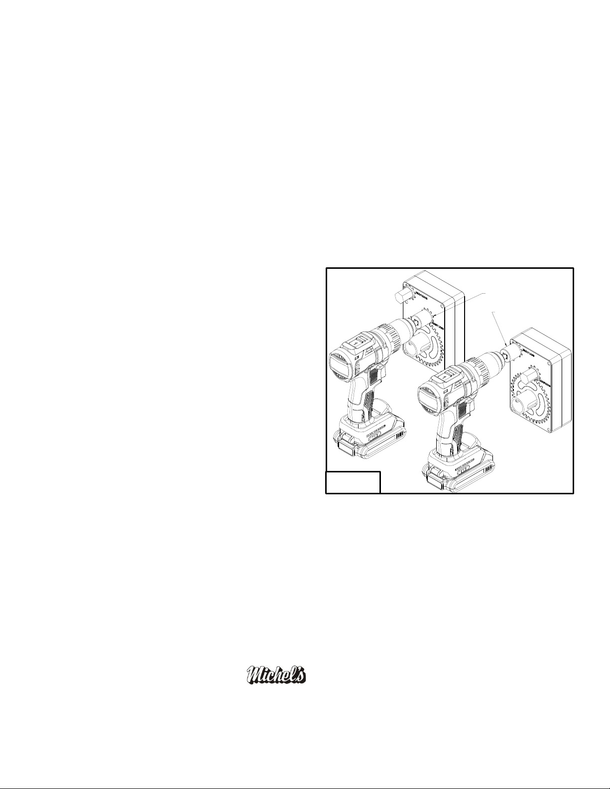
2. Slide the Michel’s EZ-Lift onto the input shaft of the landing gear
and secure with the supplied quick pin. Refer to Figure 6. Note: The
EZ-Lift can easily be removed by removing the quick pin and can be
used on other trailers. If the EZ-Lift is to remain attached to the
landing gear, Michel’s recommends using a bolt to secure it to the
output shaft. Please Note: On some trailers, the EZ-Lift can make
the trailer over the Legal Width and MUST be removed after use.
3. The EZ-Lift can be left on the landing gear even when using the
crank handle to raise and lower the trailer. But, the crank handle
must be removed when using the drill on the EZ-Lift.
*Warning the use of Hammer Drill or Impact will void the Warranty*
BRACKETS ARE ADJUSTABLE FOR WIDTH
MOUNTING BRACKETS
ARE 180° REVERSIBLE
ADJUSTABLE
MOUNTING
BRACKETS
QUICK PIN THE GEAR BOX
TO THE LANDING GEAR.
TRAILER
LANDING
GEAR
Figure 5.
Figure 4.
Figure 6.
December 2023
Step 5: Landing Gear Locking
Without locking the landing gear, there is a possibility that the landing gear will creep down. This may cause a ground
clearance problem. There are a couple of options for locking the landing gear.
1. Remove the EZ-Lift and pin the crank handle back onto the landing gear using the same quick pin.
2. Before removing the EZ-Lift, turn the quick pin so it is vertical. Remove the EZ-Lift and insert the included quick
pin with a chain attached into the input shaft of the landing gear. Attach the other end of the chain to the trailer
so the chain is close to being tight. This cable and quick pin will prevent the landing gear from creeping down.
3. If leaving he EZ-Lift on the trailer, a second hole may have to be drilled for the Safety Pin.
Operation:
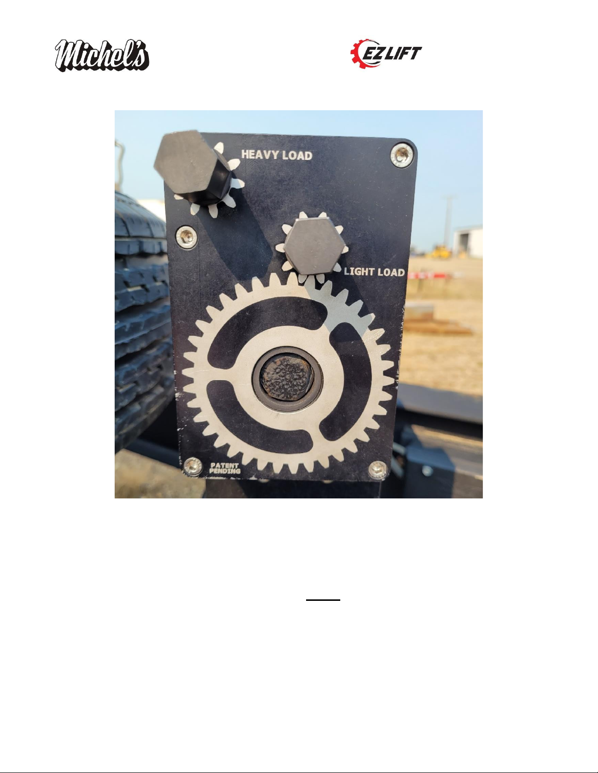
Once the Michel’s EZ-Lift is attached to the landing gear of a trailer, it is ready to be used. To operate the EZ-Lift, use a
socket adaptor (Included) with a 3/4″ socket and a cordless drill to effortlessly raise or lower the trailer. ***Warning
the use of a Hammer Drill or Impact will void the Warranty. *** There are two input shafts on the EZ-Lift, a Light Load
shaft, and a Heavy Load shaft. These inputs will be used under different load conditions. The Light load input shaft
should only be used when the landing gear is not touching the ground. For example: When lowering the landing gear to
the ground or raising the landing gear after the trailer has been hitched to the vehicle. The Heavy Load input shaft
should be used when lifting or lowering the weight of the
trailer. Note: To reduce the load stress on the drill, switch
the drill to Low speed. This will reduce the stress on the drill
and improve the battery life.
To aid in the safe operation of the Michel’s EZ-Lift, the landing
Gear, and the Cordless Drill; Use the clutch setting on the
Cordless Drill on the highest setting needed to raise the trailer
without slipping the clutch. This will help prevent any damage
if the landing gear is bottomed out in either direction. It is
good practice to place a piece of 2×6 wood or similar under
the trailer landing gear to support and distribute the weight
evenly. Make sure to chock the tires on the trailer before
uncoupling, even if on perceived flat ground.
Using the Michel’s EZ-Lift greatly reduces the fatigue of the
operator and reduces the likelihood of shoulder and elbow
injuries caused by hand cranking.
Warranty:
All Hardware carries a One Year Warranty against manufacturers defects FROM THE DATE OF PURCHASE, F.O.B.
FACTORY, St. Gregor, Saskatchewan, Canada. All warranty work must be approved by the manufacture prior to warranty
work done by an approved warranty depot. Proof of purchase must accompany all claims.
***Warning the use of a Hammer Drill or Impact will void the Warranty. ***
Industries, Ltd.
P.O. Box 119
St. Gregor, Saskatchewan
S0K 3X0 Canada
Ph# (306)366-2184 or Fax# (306)366-2145
HEAVY LOAD OPERATION
LIGHT LOAD OPERATION
Figure 7.
Other Michel's Farm Equipment manuals


Popular Farm Equipment manuals by other brands

Schaffert
Schaffert Rebounder Mounting instructions

Stocks AG
Stocks AG Fan Jet Pro Plus 65 Original Operating Manual and parts list

Cumberland
Cumberland Integra Feed-Link Installation and operation manual

BROWN
BROWN BDHP-1250 Owner's/operator's manual

Molon
Molon BCS operating instructions

Vaderstad
Vaderstad Rapid Series instructions


